Hussian Z., AbdullahM.Z., AlimuddinZ. Basic Fluid Mechanics and Hydraulic Machines
Подождите немного. Документ загружается.

110 Basic Fluids Mechanics and Hydraulic Machines
Hydraulic efficiency
power developed
by
runner
__
yQE
TJh
=
hydraulic power yQH
Mechanical efficiency
11
power developed
at
turbine shaft _
~
'1m
power developed
by
runner yQE
P
Overall efficiency
Power developed
at
turbine shaft
TJ
=
---
o hydraulic power
5.4.1
Working Proportions for Design
of
Pelton Wheel
1. Velocity
of
jet: The theoretical velocity
of
the Jet
where H = net head
Actual Velocity
of
Jet
VI
=
~2gH
Va
=
Cy~2gH
yQH
where C
y
is the coefficient
of
velocity
of
the
jet
which varies from 0.98 to 0.99.
2. Power available to the Turbine
P=
yQH
where y is the specific weight
of
water,
in
N/m
3
,
Q
is
the flow rate in m
3
/S,
H head
in
meters.
3.
Angle
~
is
the splitter angle which varies from
10
to
20
0
and relation between
~
and
exit angle
8 is
8=1t-~
4. Diameter
of
the
Jet
(d):
The
diameter
of
the
jet
is obtained
if
flow rate is known.
Flow rate Q = area
of
the
jet
x velocity
of
jet
x no.
of
jets
For a single
jet
1t
Q = - d
2
x V
4 I
(
4Q
)~
d=
1tCv~2gH
Pelton Turbine
111
5. Speed ratio (
~l
):
The speed ratio
is
the ratio
of
the velocity (u)
of
the wheel at
pitch circle to theoretical velocity
of
the jet.
In
practice the value
is
between 0.44 and
0.46 and average
is
0.45.
6. Meall Diameter oftlte Wheel
(D):
It
is
the diameter between centres
of
the buckets.
The diameter can be obtained from peripherial velocity (u)
or
nDN
u=
--
60
60u
D=-
nN
where N = speed
of
the wheel
in
revolutions/min.
7. Jet
ratil]
(m): The ratio
of
mean diameter
of
the wheel to diameter
of
the jet.
m=D/d
The Jet ratio varies between
10
to
14
and average value
of
m
is
12.
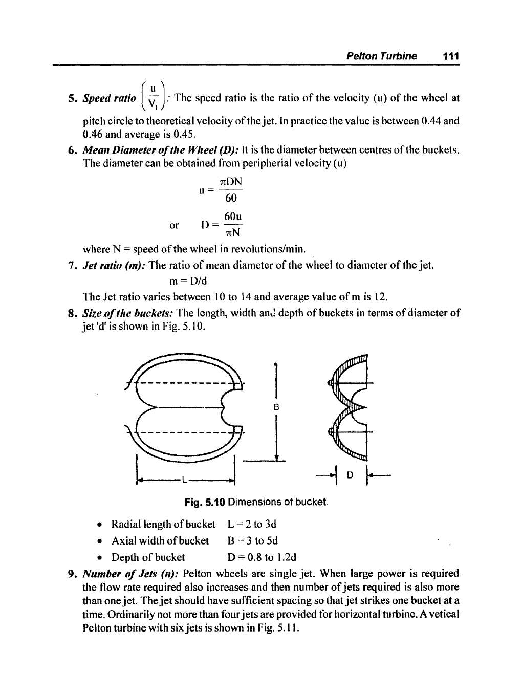
8. Size ,oft/Ie
bucket.'i:
The length, width
anJ
depth
of
buckets
in
terms
of
diameter
of
jet
'd'
is
shown
in
Fig. 5.10.
Fig. 5.10 Dimensions
of
bucket.
• Radial length
of
bucket L = 2 to 3d
• Axial width
of
bucket B = 3 to 5d
• Depth
of
bucket D = 0.8 to 1.2d
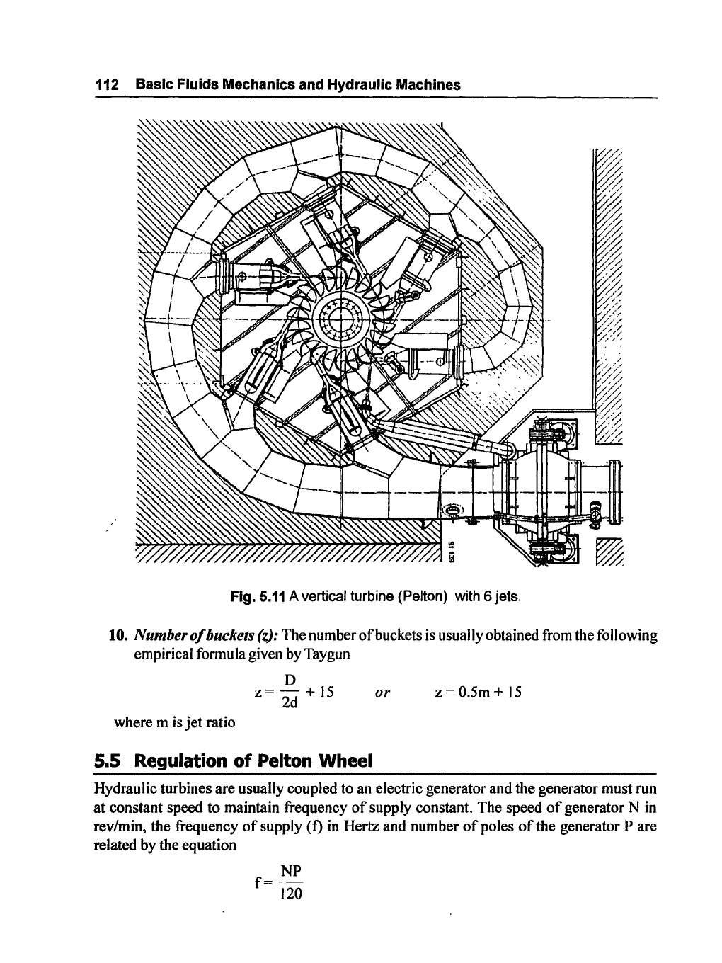
9. Number
of
Jets (n): Pelton wlteels are single jet. When large power is required
the flow rate required also increases and then number
of
jets
required is also more
than one jet. The
jet
should have sufficient spacing so that
jet
strikes one bucket at a
time. Ordinarily not more than four
jets
are provided for horizontal turbine. A vetical
Pelton turbine with six
jets
is
shown
in
Fig. 5.11.
112 Basic Fluids Mechanics and Hydraulic Machines
Fig.
5.11
A vertical turbine (Pelton) with 6 jets.
10.
Number
of
buckets (z): The number
of
buckets is usually obtained from the following
empirical formula given by Taygun
where m is
jet
ratio
o
z=
- +
15
2d
5.5 Regulation of Pelton Wheel
or
z=O.5m
+
15
Hydraulic turbines are usually coupled to an electric generator and the generator must run
at
constant speed to maintain frequency
of
supply constant. The speed
of
generator N in
rev/min, the frequency
of
supply (f)
in
Hertz and number
of
poles
of
the generator
Pare
related by the equation
NP
f=
]20
Pelton Turbine 113
The
peripheral velocity u
of
turbine wheel must remain constant as speed
is
constant.
The
velocity u and speed N are connected by the formula
nON
u=--
60
where 0 is mean diameter
of
the wheel.
u
It
is also desirable to run turbine at maximum efficiency and therefore speed ratio
VI
must remain same which means the
jet
velocity must not change as head available H is
constant. The only way
to
adjust the load is to change hydraulic power input given by
p=
yQH
As
y,
specific weight
of
water and H are constant, the only variable factor is Q volume
flow rate
of
water entering the turbine. The flow rate Q is
Q = Area
of
nozzle x velocity
of
jet
Thus flow rate will change by changing the area
of
the
jet
or
more closely the diameter
of
the
jet.
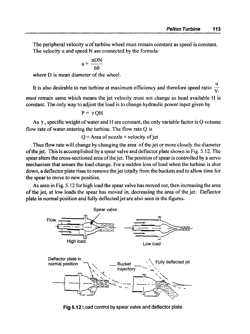
This is accomplished by a spear valve and deflector plate shown
in
Fig. 5.12. The
spear alters the cross-sectioned area
ofthe
jet.
The
position
of
spear is controlled
by
a servo
mechanism that senses the load change. For a sudden loss
of
load when the turbine is shut
down, a deflector plate rises
to
remove the
jet
totally from the buckets and to allow time for
the spear to move to new position.
As seen
in
Fig. 5.12 for high load the spear valve has moved out, then increasing the area
of
the
jet,
at low loads the spear has moved in, decreasing the area
of
the
jet.
Deflector
plate in normal position and fully deflected
jet
are also seen
in
the figures.
Spear valve
Flow
-.-(=.
--i
~~:~
-_
...
---
-.--
i V
High load
Low load
Fig 5.12 Load control
by
spear valve and deflector plate.
114 Basic Fluids Mechanics and Hydraulic Machines
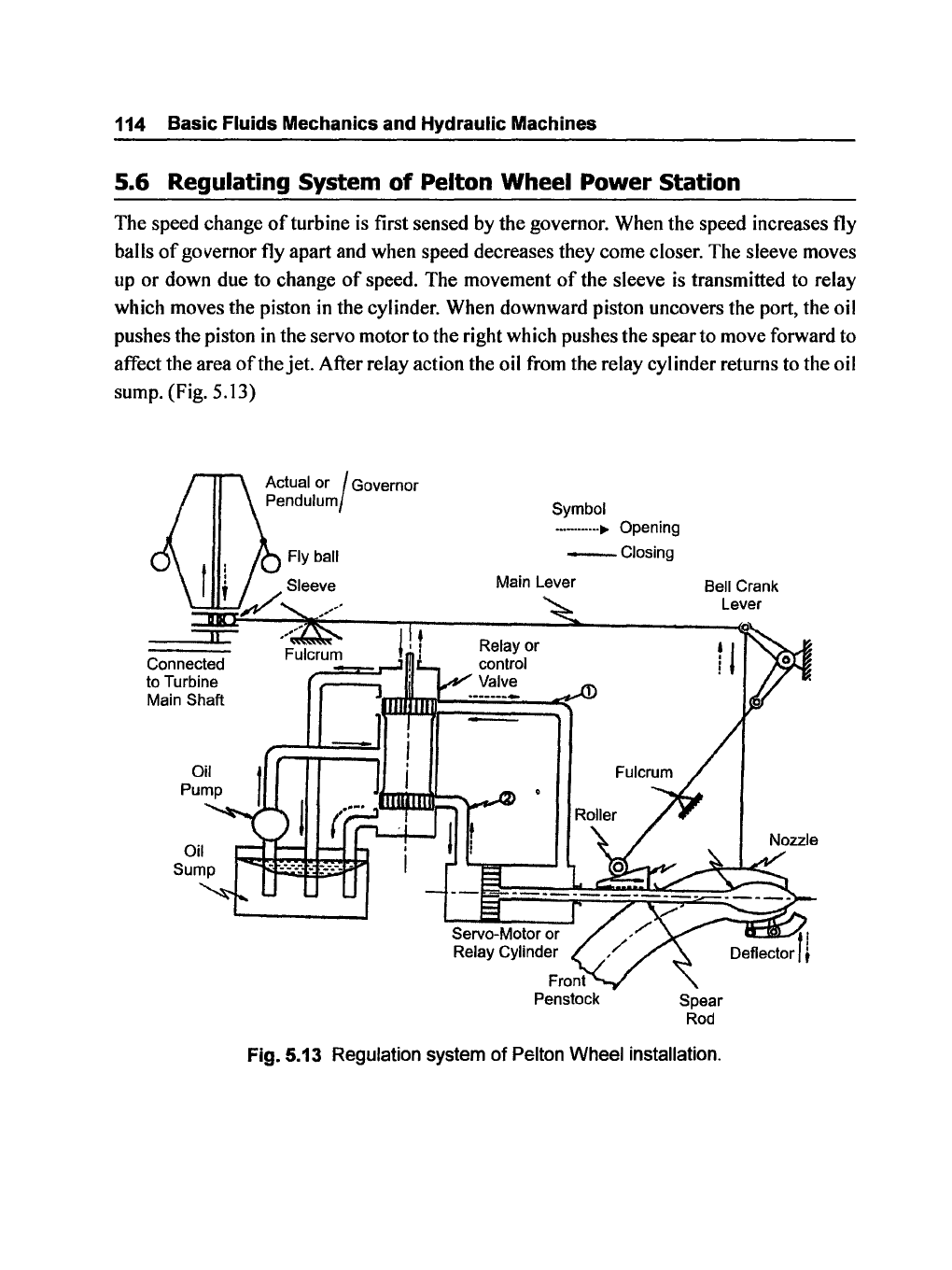
5.6 Regulating System
of
Pelton Wheel Power Station
The speed change
of
turbine
is
first sensed by the governor. When the speed increases fly
balls
of
governor fly apart and when speed decreases they come closer. The sleeve moves
up or down due to change
of
speed. The movement
of
the sleeve
is
transmitted to relay
which moves the piston in the cylinder. When downward piston uncovers the port, the oil
pushes the piston
in
the servo motor to the right which pushes the spear to move forward to
affect the area
of
the jet. After relay action the oil from the relay cylinder returns to the oil
sump. (Fig. 5.13)
Connected
to Turbine
Main
Shaft
Actual or I Governor
Pendulum
Symbol
...
-
.......
~
Opening
_Closing
Main Lever
Relay or
control
Valve
Bell Crank
Lever
Spear
Rod
Fig. 5.13 Regulation system
of
Pelton Wheel installation.
Pelton Turbine
115
Solved Examples
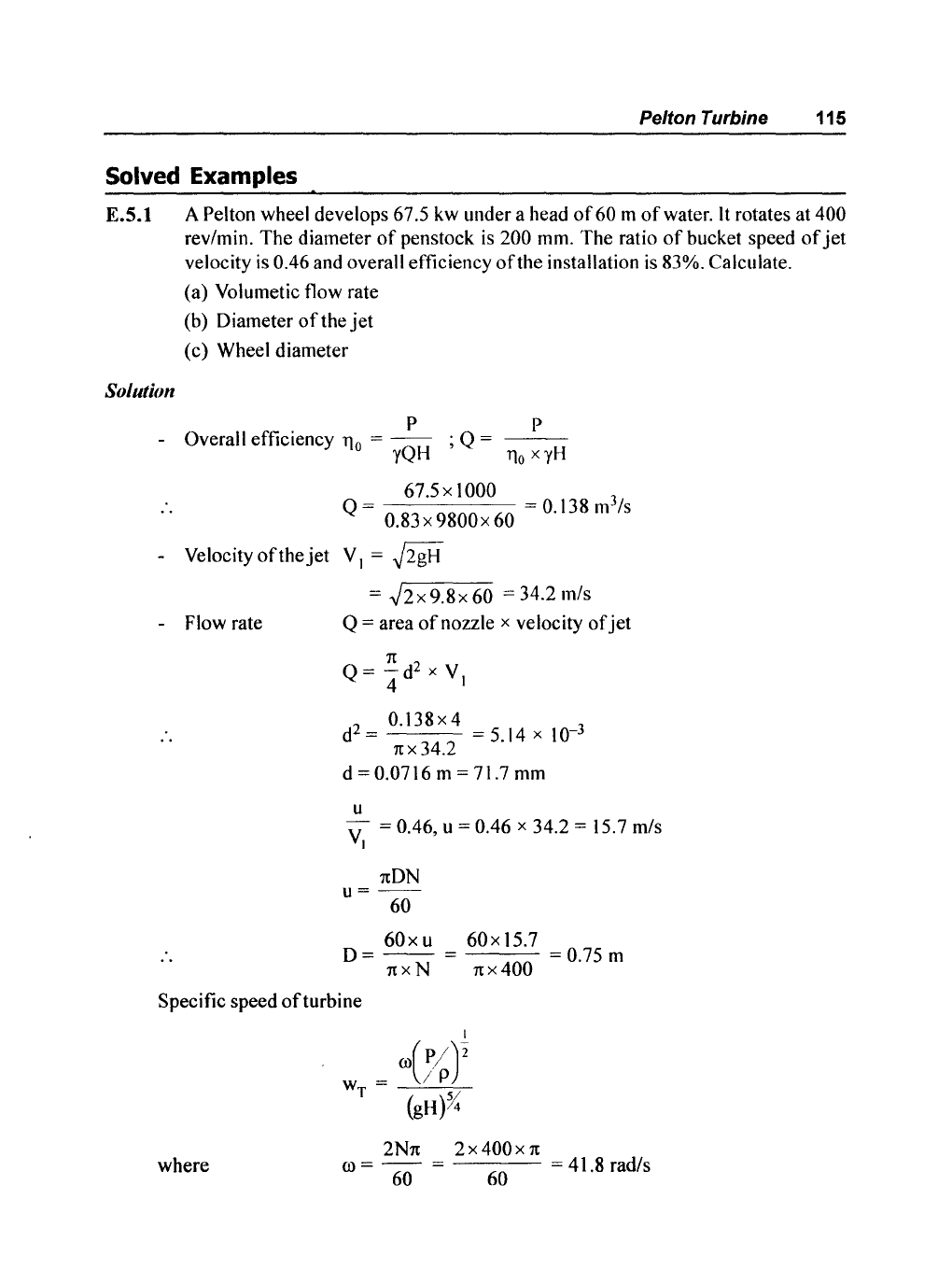
E.S.l
A Pelton wheel develops 67.5 kw under a head
of
60 m
of
water.
It
rotates at
400
rev/min.
The
diameter
of
penstock
is
200 mm.
The
ratio
of
bucket speed
of
jet
velocity
is
0.46 and overall efficiency
of
the installation
is
83%. Calculate.
(a) Volumetic flow rate
(b) Diameter
of
the
jet
(c)
Wheel diameter
Solution
P P
- Overall efficiency llo =
--
; Q =
---
yQH
llo
xyH
_
67.5x
1000 _ 3
Q-
0.83x9800x60
-0.138m
/s
- Velocity
of
the
jet
V I =
~2gH
- Flow rate
= ,J2 x 9.8 x
60
= 34.2 mls
Q = area
of
nozzle x velocity
of
jet
n
Q =
-d
2
x V
4 I
0.138x
4
d
2
=
= 5.14 x 10-
3
n x 34.2
d =
0.0716 m = 71.7 mm
u
V = 0.46, u = 0.46 x 34.2 = 15.7 mls
I
nON
u=--
60
60
x u
60
x 15.7
0=
--
=
=0.75
m
n x N
nx
400
Specific speed
of
turbine
where
w =
T
2Nn
2 x
400x
n
00=
60
= 60
= 41.8 rad/s
116 Basic Fluids Mechanics and HydraUlic Machines
Substituting,
P = 67.5 x 10
3
watt
p = I 000 kg/m
3
H=60m
(OT
= 0.11
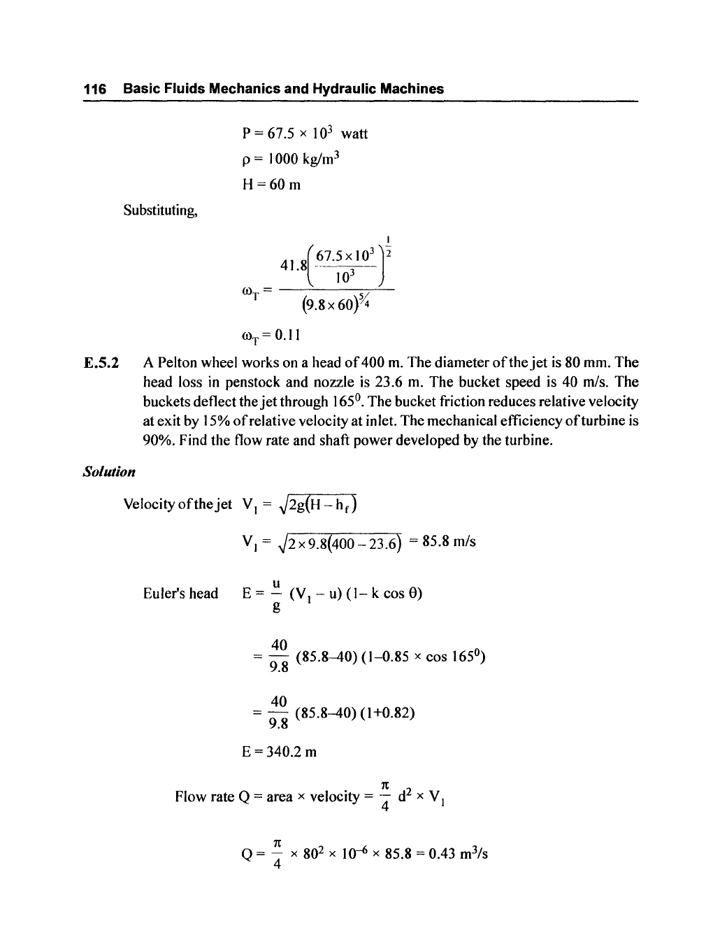
E.5.2 A Pelton wheel works on a head
of
400
m.
The diameter
of
the
jet
is 80 mm.
The
head loss in penstock and nozzle is 23.6
m.
The bucket speed is 40 m/s. The
buckets deflect the
jet
through 165°. The bucket friction reduces relative velocity
at exit by 15%
of
relative velocity at inlet. The mechanical efficiency
ofturbine
is
90%. Find the flow rate and shaft power developed by the turbine.
Solution
Velocityofthejet
VI =
~2g(H-hf)
Euler's head
VI
=
~2x9.8(400-23.6)
= 85.8 m/s
u
E=
- (V
-u)(l-kcos9)
g I
40
= 9.8
(85.8-40)
(1-0.85
x cos 165°)
40
= -
(85.8-40)
(1+0.82)
9.8
E
=340.2
m
1t
Flow rate Q = area x velocity =
4"
d
2
x V I
1t
Q
= - x 80
2
x 10-6 x 85 8 = 0 43 m
3
/s
4 . .
Pelton Turbine
117
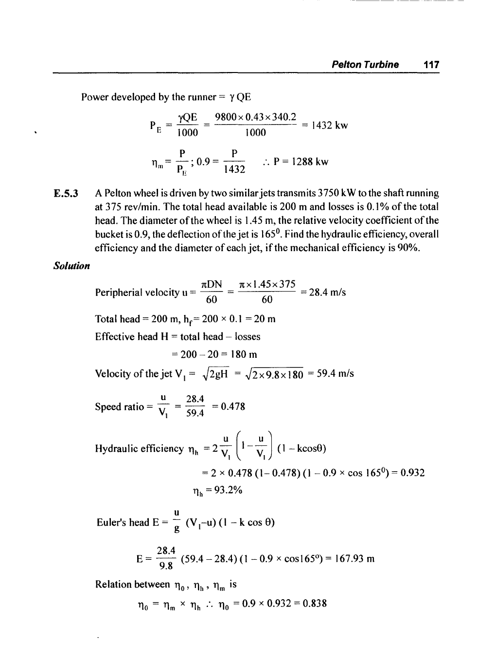
Power developed by the runner = y QE
yQE
9800 x 0.43 x 340.2
P
E
=
toOO
=
toOO
=
1432
kw
P P
11m
= P
E
; 0.9 = 1432
:.
P =
1288
kw
E.5.3 A Pelton wheel
is
driven
by
two similar
jets
transmits 3750 k W to the shaft running
at 375 rev/min. The total head available is
200 m and losses
is
0.1
%
of
the total
head. The diameter
of
the wheel
is
1.45
m,
the relative velocity coefficient
ofthe
bucket
is
0.9, the deflection
ofthe
jet
is
165°. Find the hydraulic efficiency, overall
efficiency and the diameter
of
each
jet,
if
the mechanical efficiency
is
90%.
Solution
1tON
1tx1.45x375
Peripherial velocity u =
60
= 60 = 28.4 m/s
Total head =
200
m,
h
f
= 200 x
0.1
= 20 m
Effective head
H = total head - losses
=
200 - 20 = 180 m
Velocity
of
the
jet
VI
=
~2gH
=
.J2x9.8xI80
=59.4m/s
u 28.4
Speed ratio =
VI
= 59.4 = 0.478
Hydraulic efficiency
11h
= 2
~I
(1-
~I)
(I - kcos8)
u
= 2 x 0.478
(1-
0.478)
(I
- 0.9 x cos 165°) = 0.932
11h
= 93.2%
Euler's head E
= g
(VI-u)
(I - k cos
8)
28.4
E=
-
(59.4-28.4)(1-0.9
x cosI65°) = 167.93 m
9.8
Relation between
110'
11h
'
11m
is
110
=
11m
X
11h
:.
110
= 0.9 X 0.932 = 0.838
118 Basic Fluids Mechanics and Hydraulic Machines
P 3750
hydraulic power =
~
= 0.838 = 4474 kw
also
yQH
1000 x 2 = 4474
Q
1
OOOx
4474 _ 3
2x9800x180
- 1.268 m
Is
Flow rate Q = area x velocity
of
jet
1t
Q = - d
2
x V
4 \
d
2
=
~
=
4x
1.268
= 0.0272
1txV
I
1t
x 59.4
d=
164 mm
E.S.4
In
a Pelton wheel the diameter
of
the wheel
is
2 m and angle
of
deflection is
16i).
Solution
The
jet
diameter
is
165
mm and pressure behind the nozzle
is
) 000 kN/m
2
and
wheel rotates at
320.rev/min. Find the hydraulic power developed and hydraulic
efficiency.
Pressure P = Y H
1000 x 1 0
3
H=
= 102 m
9800
:.
Velocity
ofthejet
V\ =
~2gH
=
.J2x9.8x102
= 44.7
m/s
Flow rate
1t
1t
Q = - d
2
x V = - x
165
2
x
10--6
x 44.7
4 \ 4
Q = 0.955 m
3
/s
yQH
9800x
0.955x
102
hydraulic power = 1000 = 1000 = 954.6 kW
1tDN
1tx2x320
u =
60
= 60 = 33.4
m/s
u 33.4
Speed ratio
VI
= 44.7 = 0.747
Pelton Turbine 119
hydraulic efficiency
11h
= 2 (
~I)
(I
-
~I)
(l-cos9)
11h
=2
x 0.747 (1-0.747)
(1-cos
162°)=0.737
E.S.S A Pelton
turbine
develops 8 MW under a head
of
130 m
at
a speed
of
200 rev/min. The following are the particulars
of
Pelton wheel.
• Coefficient
of
velocity
(C)
of
the nozzle 0.98
•
Speed ratio 0.46
•
jet
diameter
1/9
of
diameter
of
the wheel
• overall efficiency 87%
Determine
Solution
- flow required
- diameter
of
the wheel
- diameter
of
the
jet
- number
of
jets
- number
of
buckets
Velocity
of
the
jet
= C
v
~2gH
= 0.98 .J2 x 9.8 x 130 = 49 mls
u
Speed ratio V = 0.46; u = 0.46 x 49 = 22.54 mls
I
1tON
Peripherial Velocity u =
60
60x
u
60x22.5
0=--=---
1tX
N
1tX
200
= 2.15 m
d
o 9
o 2.15
d =
9 =
-9-
= 0.238
m;
d = 238
mm
P
Overall efficiency
110
=
yQH
;
P
Q=---
110
x
yx
H