Hussian Z., AbdullahM.Z., AlimuddinZ. Basic Fluid Mechanics and Hydraulic Machines
Подождите немного. Документ загружается.

120 Basic Fluids Mechanics and Hydraulic Machines
8x
10
3
X
10
3
Q=
=7.2m
3
/s
0.87 x 9800 x 130
Flow rate Q = area
of
jet
x velocity x
no.of
jets
1t
7 2 = - x 0 238
2
x 49 x n
. 4 .
n=3
D 2.15
Number
of
buckets
z = -
+
15
= +
15
= 20
2d 2xO.238
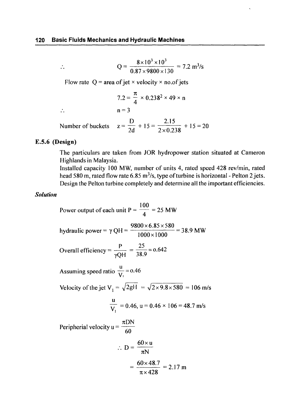
E.S.6 (Design)
Solutio"
The particulars are taken from JOR hydropower station situated at Cameron
Highlands
in
Malaysia.
Installed capacity
100
MW,
number
of
units 4, rated speed 428 rev/min, rated
head
580
m,
rated flow rate 6.85 m
3
/s, type
of
turbine is horizontal- Pelton 2 jets.
Design the Pelton turbine completely and determine all the important efficiencies.
100
Power
output
of
each unit P = 4 = 25 MW
9800 x 6.85 x 580
hydraulic power = y QH = 1000 x 1000 = 38.9 MW
P
25
Overall efficiency =
--
=
--
= 0.642
yQH
38.9
u
Assuming speed ratio
v:
= 0.46
Velocity
of
the
jet
V I =
~2gH
=
.J2
x 9.8 x 580 = 106 m/s
u
V = 0.46, u = 0.46 x 106 = 48.7 m/s
I
1tDN
Peripherial velocity u =
60
60xu
:.
D=-;N
60x
48.7 = 2.17 m
1tX
428
Pelton Turbine
121
1t
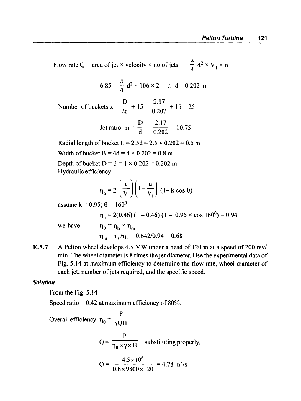
Flow rate Q = area
of
jet
x velocity x no
of
jets
="4
d
2
x V I x n
1t
6.85 =
"4
d
2
x 106 x 2
..
d = 0.202 m
D 2.17
Numberofbucketsz=
- +
15=
--
+
15=25
2d 0.202
D 2.17
Jet ratio m =
d = 0.202 = 10.75
Radial length
of
bucket L = 2.5d = 2.5 x 0.202 = 0.5 m
Width
of
bucket B = 4d = 4 x 0.202 = 0.8 m
Depth
of
bucket 0 = d = I x 0.202 = 0.202 m
Hydraulic efficiency
~h
~
2 (
~J
(1-
~J
(1-
k cos
9)
assume k = 0.95; e = 160
0
11h
= 2(0.46)
(1
- 0.46)(1 - 0.95 x cos 160
0
)
= 0.94
we have
110
=
11h
x
11m
11m
=
11i11h
= 0.642/0.94 = 0.68
E.S.7 A Pelton wheel develops 4.5 MW under a head
of
120 m at a speed
of200
revl
min. The wheel diameter
is
8 times the
jet
diameter. Use the experimental data
of
Fig. 5.14 at maximum efficiency to determine the flow rate, wheel diameter
of
each
jet,
number
of
jets
required, and the specific speed.
Solution
From the Fig. 5.14
Speed ratio =
0.42 at maximum efficiency
of
80%.
P
Overall efficiency
110
= 'rQH
P
Q =
110
x'Y
x H substituting properly,
4.5
x
10
6
Q = = 4.78 m
3
/s
0.8x 9800x 120

122 Basic Fluids Mechanics and Hydraulic Machines
1.0
0.8
0.6
llh
0.4
0.2
I
I
I
I I
L
~
-
;Ie-
..
_\
\
\,
/
,tJ
i
\
-
-
//'
1\
~:
•
\
0.2
0.4 0.6 0.8
u
10-
.
VI
Fig. 5.14 Speed ratio versus efficiency for a laboratory-scale Pelton turbine:
solid line,
(c
v
= 0.94, 8 = 168°); dashed line, experimental data.
Velocity
of
the
jet
Also
Peripherial velocity
VI
=
~2gH
=
.J2
x9.8x
120 = 48.5 m/s
u
V = 0.42
:.
u = 0.42 x 48.5 = 20.37 m/s
I
nDN
60x
u
u=--'D=--
60'
n x N
60x
20.37
D=
nx200
= 1.95 m
D 1.95
Diameter
of
jet
= 8 =
-8-
= 0.243 m
Number
of
jets
n can be obtained by
Q = area
of
jet
x velocity x no.
of
jets
n
Q
=
-d
2
x V x n
4 I
n
4.78 =
4'
x 0.243
2
x 48.5 x n
n=2
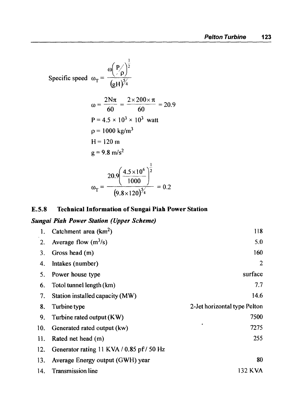
Specific speed (()T =
2Nl£
2x
200x
1£
(()=6Q=
60
=20.9
P = 4.5 x
10
3
x
10
3
watt
p =
1000 kg/m
3
H=
120 m
g
= 9.8 mls
2
I
20.9(4.5 x
10
6
)2
1000
(()
=
---'------,"--
= 0.2
T (9.8x 120)%
Pelton Turbine 123
E.S.S Technical Information
of
Sungai Piah
Power
Station
Sungai Piah Power Station (Upper Scheme)
1.
Catchment area (km
2
)
118
2.
Average flow (m3/
s
)
5.0
3.
Gross head (m)
160
4.
Intakes (number)
2
5.
Power house type
surface
6.
Totol tunnel length (km)
7.7
7.
Station installed capacity (MW)
14.6
8.
Turbine type
2-Jet horizontal type
Pelton
9.
Turbine rated output
(K
W)
7500
10.
Generated rated output (kw)
7275
11.
Rated net head (m)
255
12.
Generator rating
11
KVA
/ 0.85
pf
/50
Hz
13.
Average Energy output (GWH) year
80
14.
Transmission line
132
KVA
124 Basic Fluids Mechanics and Hydraulic Machines
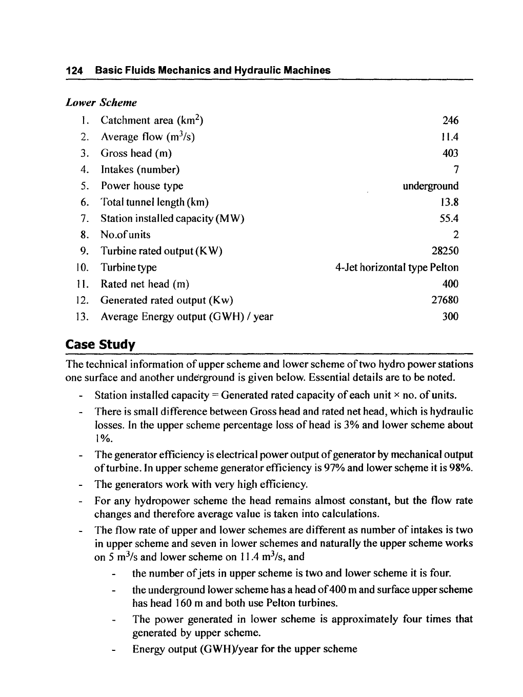
Lower Scheme
I.
Catchment
area
(km
2
)
2. Average flow (m3/
s
)
3. Gross head
(m)
4. Intakes (number)
5. Power house type
6. Total tunnel length (km)
7. Station installed capacity
(MW)
8.
No.ofunits
9. Turbine rated output
(K
W)
10.
Turbine type
II.
Rated net head (m)
12.
Generated rated output
(Kw)
13. Average Energy output
(GWH)
/
year
Case Study
246
11.4
403
7
underground
13.8
55.4
2
28250
4-Jet horizontal type Pelton
400
27680
300
The
technical information
of
upper scheme
and
lower scheme
of
two hydro
power
stations
one
surface and
another
underground is given below. Essential details are to be noted.
Station installed capacity
= Generated rated capacity
of
each unit x no.
of
units.
There
is
small difference between Gross head and rated
net
head, which
is
hydraulic
losses.
In
the upper scheme percentage loss
of
head is
3%
and lower scheme about
1%.
The
generator efficiency is electrical
power
output
of
generator by mechanical output
ofturbine.
In
upper scheme generator efficiency is
97%
and lower
sch~me
it is 98%.
The
generators work with very high efficiency.
For
any
hydropower scheme the head remains almost constant, but the flow rate
changes and therefore average value
is
taken into calculations.
The
flow rate
of
upper and lower schemes
are
different as number
of
intakes is
two
in upper scheme and seven in lower schemes
and
naturally the
~pper
scheme works
on 5 m
3
/s and lower scheme on 11.4 m
3
/s, and
the number
of
jets
in upper scheme is
two
and lower scheme it is four.
the underground lower scheme has a head
of
400 m and surface upper scheme
has head
160 m and both use Pelton turbines.
The
power
generated in
lower
scheme
is approximately four times
that
generated by upper scheme.
Energy output
(GWH)/year
for
the upper scheme
Pelton Turbine 125
Station installed capacity
in
Watts x number
of
hours/year
14.6 x
10
3
X
10
3
X 8760
= 127.89
(GWH)/year
= 127.89
Average energy output given is 80(GWH)/year
80
Generating efficiency = 127.89 = 62%
- Energy output (GWH)/year for the lower scheme
= station installed capacity
in
Watts x
no.ofhours/year
55.4x
10
3
x
10
3
x8760
----10-
9
---
= 485
= (GWH)/year = 485
- Average energy output given is
300 (GWH)/year
300
Generating efficiency = 485 =
62%
- Some
of
the reasons for this deficiency in generating efficiency is due to shut
down
of
the units for repair and maintenance during the year, fall short
of
water level
in
the reservoir
or
power not required by the main grid and hence
some units are shut down.
-
The
most important parameters are frequency
of
supply which must be 50 HZ
and may fluctuate within very narrow limits and also the power factor
(pt)
which must be 0.85 - 0.9.
- Electrical charges are given
per
unit
of
electricity which is kWh.
Thus
units
of
electrical energy generated for upper scheme.
80x
10
9
80 GWH/year = = 80 million units/year
10
3
Electrical, energy generated for lower scheme
300x
10
9
300(GWH)/year = -1--'03=--
= 300 million units/year

"This page is Intentionally Left Blank"
CHAPTER
- 6
Francis
Turbine
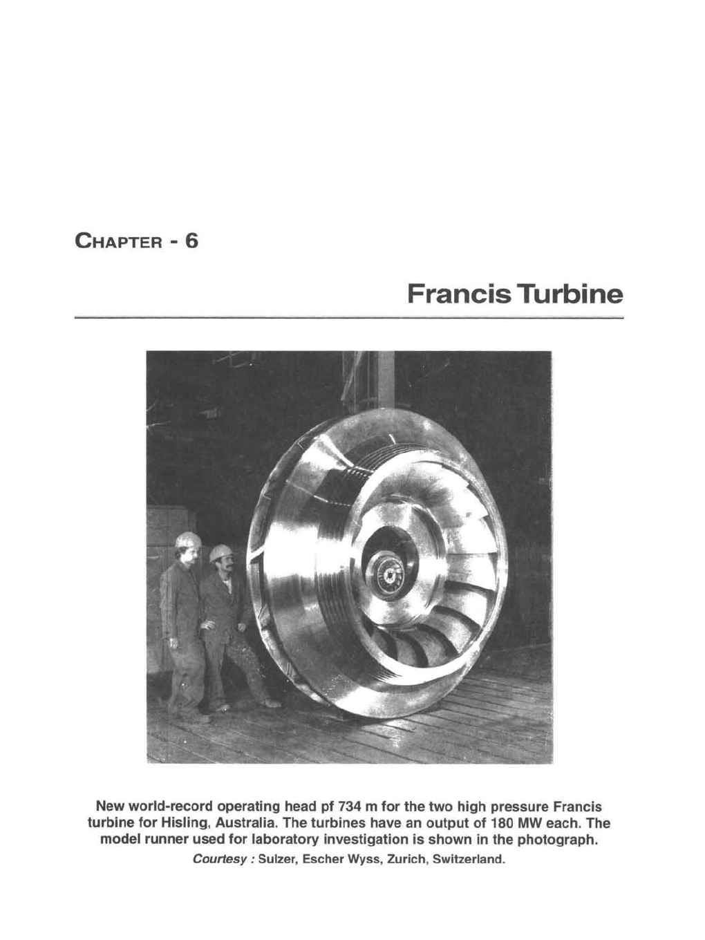
New
world-record
operating head
pf
734 m
for
the
two
high
pressure Francis
turbine
for
Hisling, Australia. The
turbines
have an
output
of
180 MW each. The
model
runner
used
for
laboratory
investigation
is
shown
in
the
photograph.
Courtesy:
Sulzer, Escher Wyss, Zurich, Switzerland.

"This page is Intentionally Left Blank"
Francis
Turbine
129
6.1 Introduction
The
hydraulic turbines are classified into two types, impulse and reaction.
As explained earlier
in
impulse turbines, there is
no
pressure drop across
the
moving
blades, whereas in reaction turbines the pressure drop is divided in the guide vanes
and
moving blades.
The reaction turbines are low head high flow rate machines.
For
raction turbines, the rotor
is surrounded by a casing (or volute), which is completely filled with the working fluid. Turbines
are manufactured in a variety
of
configurations, radical flow, axial flow and mixed flow.
Typical radial and mixed flow hydraulic turbine is Francis turbine, named after James B.
Francis, an American engineer. In this turbine the energy available in water is transfered to
the shaft by means
of
a rotating runner
and
resulting torque transferred by rotating shaft can
drive the eletric generator.
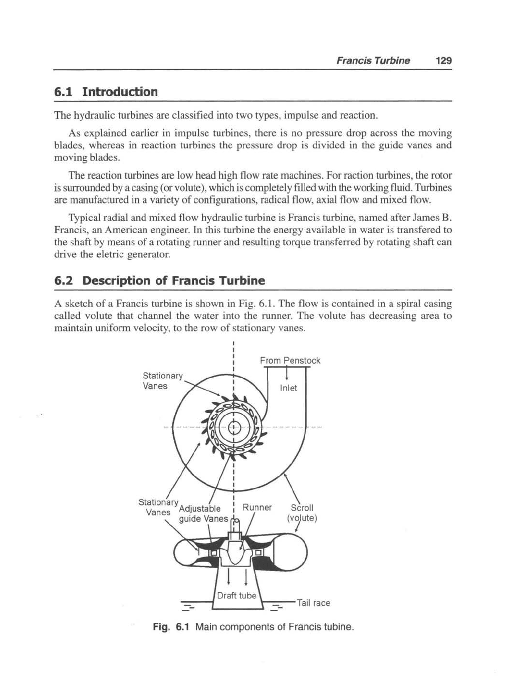
6.2 Description of Francis Turbine
A sketch
of
a Francis turbine is shown in Fig. 6.1.
The
flow is contained in a spiral casing
called volute that channel
the
water into the runner.
The
volute has decreasing area to
maintain uniform velocity, to the
row
of
stationary vanes.
Stationary
Vanes
From Penstock
Inlet
Runner
\
Scroll
(v~ute)
------
\---Tail
race
'----_
....
-
Fig.
6.1
Main components of Francis tubine.