Inversin R. Allen Micro-hydropower Sourcebook
Подождите немного. Документ загружается.

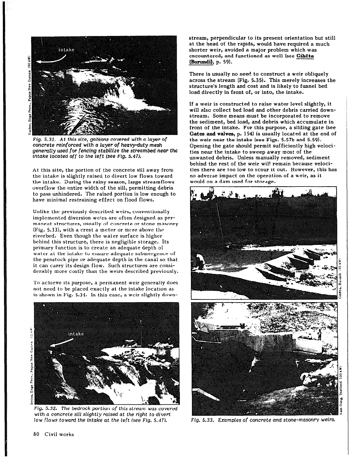
Fig.
5.31. At this
site,
gabions covered
with
a layer of
concrete reinforced with
a
layer
of heavy-duty
mesh
generally
used for fencing stabilize
the streambed near the
intake
located
off
to the left (see Fig. 5.47).
At this site, the portion of the concrete sill away from
the intake is slightly raised to divert low flows toward
the intake. During the rainy season, large streamflows
overflow the entire width of the sill, permitting debris
to pass unhindered. The raised portion is low enough to
have minimal restraining effect on flood flows.
Unlike the previously described weirs, conventionally
implemented diversion weirs are often designed as per-
manent structures, usually of concrete or stone masonry
(Fig. 5.33), with a crest a meter or mere above thr
riverbed. Even though the water surface is higher
behincl this structure, there is negligible storage. Its
primary function is to create an adequate depth of
water at the intake to ensure adequate submergence of
the penstock pipe or adequate depth in the canal so that
it can carry its design flow. Such structures are consi-
derably more costly than the weirs described previously.
To achieve its purpose, a permanent weir generally does
not need to be placed exactly at the intake locatlon as
is shown in Fig. 5.34. In this case, a weir slightly down-
Fig. 5.32. The bedrock portion
of
this
stream
was covered
with a concrete sill slightiy raised at the right to divert
low flows toward the intake at the
left (see
Fig. S.-l7).
stream, perpendicular to its present orientation but still
at the head of the rapids, would have required a much
shorter weir, avoided a major problem which was
encountered, and functioned as well (see Gihhta
rnunmdil, p. 59).
There is usually no need to construct a weir obliquely
across the stream (Fig. 5.35). This merely increases the
structure’s length and cost and is likely to funnel bed
load directly in front of, or into, the intake.
If a weir is constructed to raise water level slightly, it
will also collect bed load and other debris carried down-
stream. Some means must be incorporated to remove
the sediment, bed load, and debris which accumulate in
front of the intake. For this purpose, a sliding gate (see
Gates and valves, p. 154) is usually located at the end of
the weir near the intake (see Figs. 5.57b and 5.59).
Opening the gate should permit sufficiently high veloci-
ties near the intake to sweep away most of the
unwanted debris. Unless manually removed, sediment
behind the rest of the weir wil! remain because veloci-
ties there are too low to scour it out. However, this has
no adverse impact on the operation of a weir, as it
would on a dam used for storage.
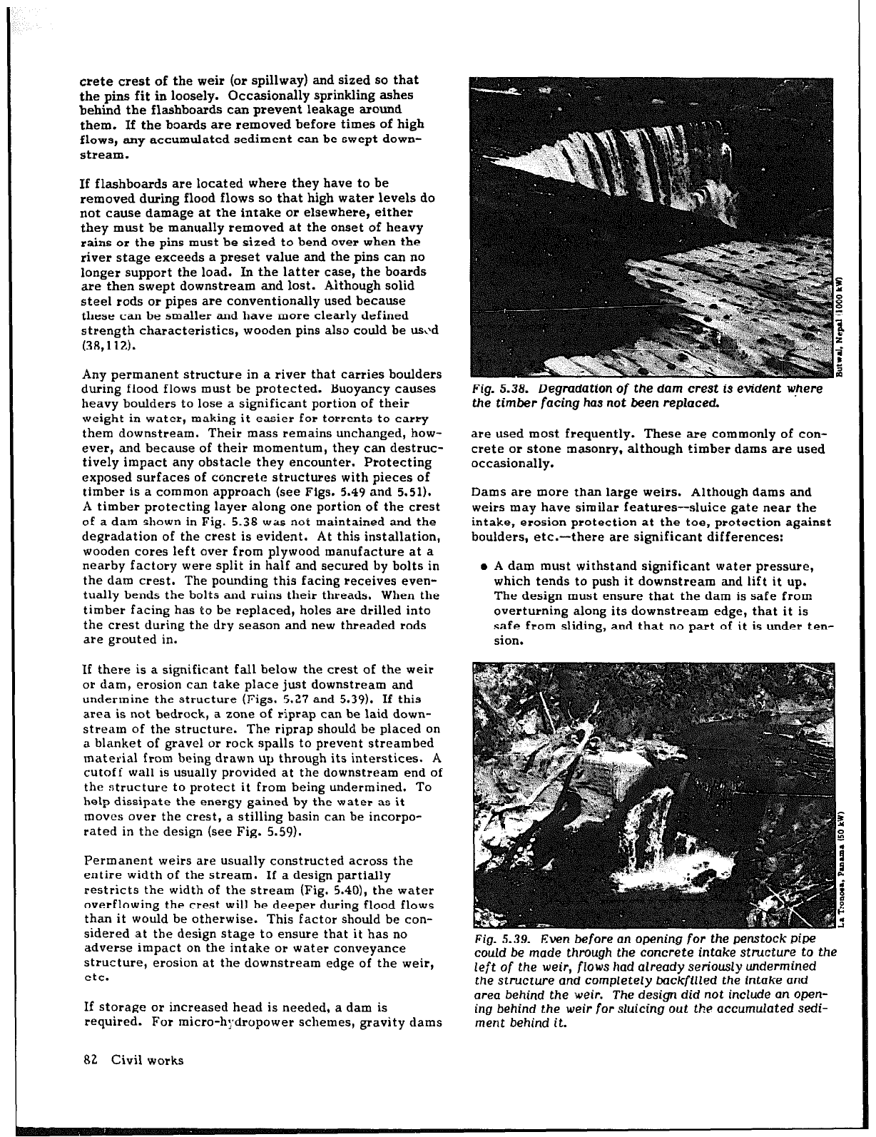
Fig. 5.33. Examples
of concrete
and stone-masonry weirs.
80 Civil works
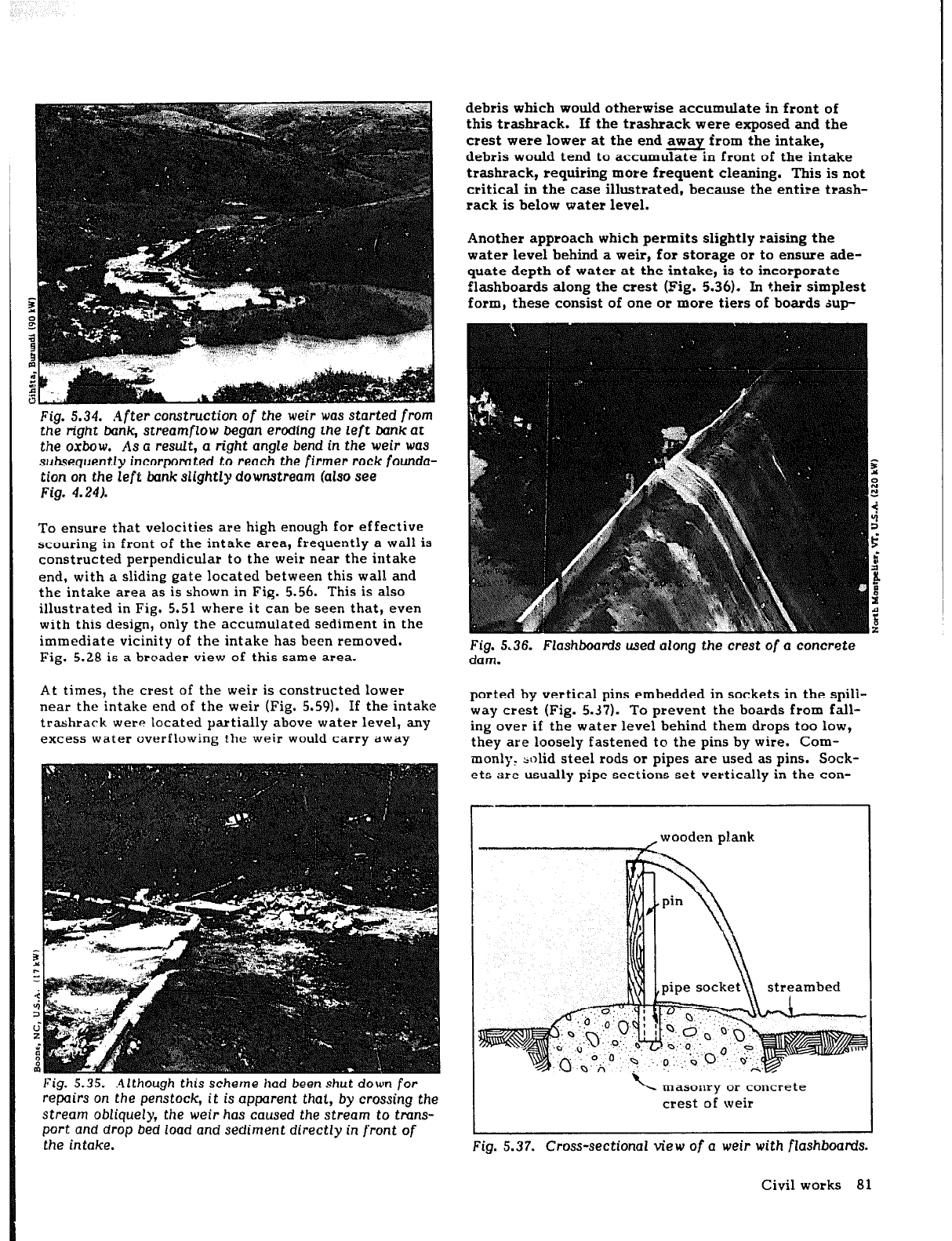
Fig.
5.34.
.4fter
construction of the weir was started fmm
the
right bank,
streamflow
began
eroding the left bank at
the oxbow, As a result, a right angle bend
in the weir was
subsequently incorporated to reach the firmer rock founda-
tion
on the left bunk slightly downstream
(also see
Figm 4.24).
To ensure that velocities are high enough for effective
scouring in front of the intake area, frequently a wall is
constructed perpendicular to the weir near the intake
end, with a sliding gate located between this wall and
the intake area as is shown in Fig. 5.56. This is also
illustrated in Fig. 5.51 where it can be seen that, even
with this design, only the accumulated sediment in the
immediate vicinity of the intake has been removed.
Fig. 5.28 is a broader view of this same area.
At times, the crest of the weir is constructed lower
near the intake end of the weir (Fig. 5.59). If the intake
trashrack were located partially above water level, any
excess water overflowing the weir would carry away
Fig. 5.35. .4lthough this
scheme had
been
shut
down for
repairs
on
the penstock,
it is apparent that,
by crossing
the
stream obliquely, the
weir
has caused
the
stream
to tmns-
port and drop bed load and
sediment directly
in front of
the
intake.
debris which would otherwise accumulate in front of
this trashrack. If the trashrack were exposed and the
crest were lower at the end away from the intake,
debris would tend to accumulate in front of the intake
trashrack, requiring more frequent cleaning. This is not
critical in the case illustrated, because the entire trash-
rack is below water level.
Another approach which permits slightly raising the
water level behind a weir, for storage or to ensure ade-
quate depth of water at the intake, is to incorporate
flashboards along the crest (Fig. 5.36). In their simplest
form, these consist of one or more tiers of boards sup-
Fig.
5.36. Flashboards used along the crest of
a
concrete
dam.
ported by vertical pins embedded in sockets in the spill-
way crest (Fig. 5.37). To prevent the boards from fall-
ing over if the water level behind them drops too low,
they are loosely fastened to the pins by wire. Com-
monly, solid steel rods or pipes are used as pins. Sock-
ets are usually pipe sections set vertically in the con-
-
masonry
or
concrete
crest of weir
A
Fig.
5.37. Cross-sectional view of a weir with flashboards.
Civil works 81
Crete crest of the weir (or spillway) and sized
SO
that
the pins fit in loosely. Occasionally sprinkling ashes
behind the flashboards can prevent leakage around
them. If the boards are removed before times of high
flows, any accumulated sediment can be swept down-
stream.
If flashboards are located where they have to be
removed during flood flows so that high water levels do
not cause damage at the intake or elsewhere, either
they must be manually removed at the onset of heavy
rains or the pins must be sized to bend over when the
river stage exceeds a preset value and the pins can no
longer support the load. In the latter case, the boards
are then swept downstream and lost. Although solid
steel rods or pipes are conventionally used because
these can be smaller and have more clearly defined
strength characteristics, wooden pins also could be us\>d
(38,112).
Any permanent structure in a river that carries boulders
during flood flows must be protected. Buoyancy causes
heavy boulders to lose a significant portion of their
weight in water, making it easier for torrents to carry
them downstream. Their mass remains unchanged, how-
ever, and because of their momentum, they can destruc-
tively impact any obstacle they encounter. Protecting
exposed surfaces of concrete structures with pieces of
timber is a common approach (see Figs. 5.49 and 5.51).
A timber protecting layer along one portion of the crest
of a dam shown in Fig. 5.38 was not maintained and the
degradation of the crest is evident. At this installation,
wooden cores left over from plywood manufacture at a
nearby factory were split in half and secured by bolts in
the dam crest. The pounding this facing receives even-
tually bends the bolts and ruins their threads. When the
timber facing has to be replaced, holes are drilled into
the crest during the dry season and new threaded rods
are grouted in.
If there is a significant fall below the crest of the weir
or dam, erosion can take place just downstream and
unclermine the structure (Figs. 5.27 and 5.39). If this
area is not bedrock, a zone of riprap can be laid down-
stream of the structure. The riprap should be placed on
a blanket of gravel or rock spalls to prevent streambed
material from being drawn up through its interstices. A
cutoff wall is usually provided at the downstream end of
the structure to protect it from being undermined. To
help dissipate the energy gained by the water as it
moves over the crest, a stilling basin can be incorpo-
rated in the design (see Fig. 5.59).
Permanent weirs are usually constructed across the
entire width of the stream. If a design partially
restricts the width of the stream (Fig. 5.40), the water
overflowing the crest will be deeper during flood flows
than it would be otherwise. This factor should be con-
sidered at the design stage to ensure that it has no
adverse impact on the intake or water convey‘ance
structure, erosion at the downstream edge of the weir,
etc.
If storage or increased head is needed, a dam is
required. For micro-hydropower schemes, gravity
dams
82 Civil works
Fig. 5.38. Degradation
of the
dam crest is
evident where
the
timber
facing has not been replaced.
are used most frequently. These are commonly of con-
crete or stone masonry, although timber dams are used
occasionally.
Dams are more than large weirs. Although dams and
weirs may have similar features-sluice gate near the
intake, erosion protection at the toe, protection against
boulders, etc.- there are significant differences:
o A dam must withstand significant water pressure,
which tends to push it downstream and lift it up.
The design must ensure that the dam is safe from
overturning along its downstream edge, that it is
safe from sliding, and that no part of it is under ten-
sion.
Fig. 5.39. Even before
an opening
for the
penstock
pipe
could
be
made through the concrete intake
structure to the
left of the
weir,
flows
had
already seriously undermined
the structure
and
completely backfilled
the intake and
area behind
the
weir.
The
design
did not include an open-
ing behind the weir for sluicing out the accumulated sedi-
ment behind
it.
i gabions
Fig. 5.40. This design of
a
weir with
drop
intake
and
wingwalls,
proposed
for use at
a site in Nepal,
reduces
the
width of
the
stream at this point.
To preclude any adverse
impect on thfs structure during flood flows,
the
increase
in
stage upstream of the weir
caused
by constriction of the
flow must be considered during the
design
phase. (One-
meter contours are shown.)
m Piping-the carrying away of finer foundation mate-
rial when water seeps beneath the dam under suffi-
cient pressure and velocity--can be a significant
problem and undermine the structure, unless the dam
is built on bedrock.
o The bearing strength of the dam’s foundation must
be sufficient to support the weight of the structure.
Most of these factors are not critical in the design of
weirs because their size is small and minimal water
pressures are encountered.
When small dams are constructed in developing coun-
tries, stone masonry is used more often than concrete
(Fig. 5.41). Cement can be difficult to obtain, costly,
and heavy to transport, especially into remote areas.
Stone-masonry structures require less concrete. On the
other hand, stone-masonry work requires special skills
and a larger labor input, but this poses no major con-
straints in most developing countries.
A timber dam which has been popular for generations is
the crib dam. It is built of green logs or heavy timbers
stacked perpendicular to each other and spiked
together. The spaces in between are filled with rocks
and gravel. This structure often requires no cofferdam,
because the cribwork offers little resistance to flow
during construction. The upstream side is covered with
planks and then clay and earth to minimize leakage.
Cutoff walls are incorporated at the toe and heel of the
dam to increase the length of the path of percolation
beneath the dam and thereby reduce piping. This type
of dam can be attractive in remote areas because it
requires very few materials from outside the region.
Fig. 5.41.
The portion of a stone-masonry dam
on the left
bunk has been completed. Laborers are excamting
for tke
remaining
portion while
an earth
cofferdam visible
at the
left
keeps water outside
the
work area. Buttresses support
the outside walls
of
the settling basin at the
far
right.
Another timber dam is a wooden frame and deck dam
(Fig. 5.421, which can be built on either earth or rock
foundation. It is composed of a timber deck supported
by a timber frame. This is not a gravity dam; the
weight of water is the principal force holding the dam in
place. Wooden dams deteriorate rapidly if not continu-
ously wet.
Although earth dams can be built on almost any founda-
tion, as can earth weirs (Fig. 5.431, they are rarely used -
Fig. 5.42. A wooden
frame
and deck
dam.
Civil works 83
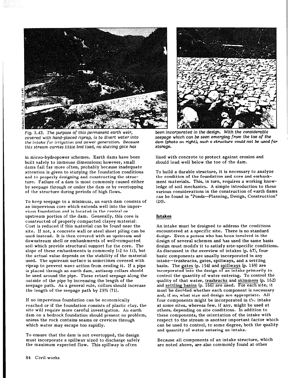
Fig. 5.43. The
purpose of
this permanent earth weir,
covered with hand-placed riprap, is to divert Water into
the intake
for
irrigation and
power
generation. Because
this stream
carries
little
bsd
load,
no
sluicing gate
has
in micro-hydropower schemes. Earth dams have been
built safely to immeuse dimensions; however, small
dams fail far more often, probably because inadequate
attention is given to studying the foundation conditions
and to properly designing and constructing the struc-
ture. Failure of a dam is most commonly caused either
by seepage through or under the dam or by overtopping
of the structure during periods of high flows.
To keep seepage to a minimum, an earth dam consists of
an impervious core which extends well into the impcr-
vious foundation and is located in the central or
upstream portion of the dam. Generally, this core is
constructed of properly compacted clayey material.
Cost is reduced if this material can be found near the
site. If not, a concrete wall or steel sheet piling can be
used instead. It is then covered with an upstream and
downstream shell or embankments of well-compacted
soil which provide structural support for the core. The
slope of these embankments is commonly 1:2 to 1:3, but
the actual value depends on the stability of the material
used. The upstream surface is sometimes covered with
riprap to prevent wavs action from eroding it. If a pipe
is placed through an earth dam, antiseep collars should
be used around the pipe. These retard seepage along the
outside of the pipe by increasing the length of the
seepage path. As a general rule, collars should increase
the length of the seepage path by 25% (71).
If no impervious foundation can be economically
reached or if the foundation consists of plastic clay, the
site will require more careful investigation. An earth
dam on a bedrock foundation should present no problem,
unless the rock contains seams or crevices through
which water may escape too rapidly.
To ensure that the dam is not overtopped, the design
must incorporate a spillway sized to discharge safely
the maximum expected flow. This spillway is often
84 Civil works
been
incorporated in the design.
With the
considerable
seepage which
can be seen emerging from the toe of the
dam
(photo 011
right), such a
structure could
not be
used for
stomge.
lined with concrete to protect against erosion and
should lead well below the toe of the dam.
To build a durable structure, it is necessary to analyze
the condition of the foundation and core and embank-
ment materials. This, in turn, requires a working know-
ledge of soil mechanics. A simple introduction to these
various considerations in the construction of earth dams
can be found in “Ponds--Planning, Design, Construction”
(20).
Intakes
An intake must be designed to address the conditions
encountered at a specific site. There is no standard
design. Even a person who has been involved in the
design of several schemes and has used the same basis
design must modify it to satisfy site-specific conditions.
As discussed in the overview of intakes (p. 67), four
basic components are usually incorporated in any
intake-trashracks. eates. snillwavs. and a settling
basin. The gates (p.Y154)Said YilIways (p. 159) are
incorporated into the design of an intake primarily to
control the quantity of water entering. To control the
quality of that water, trashracks and skimmers (p. 162)
and settling basins (p. 166) are used. For each site, it
must be decided whether each component is necessary
and, if so, what size and design are appropriate. All
four components might be incorporated in
the
intake
at some sites, whereas few, if any, might be used at
others, depending on site conditions. In addition to
these components, the orientation of the intake with
respect to the stream is another important factor which
can be used to control, to some degree, both the quality
and quantity of water entering an intake.
Because all components of an intake structure, which
are noted above, are also commonly found at other
points in a hydropower scheme, specific design consid-
erations for each of these are discussed in Other
corn--
~+ents (p. 154). Th
is section presents a variety of
designs which are currently in use and illustrates how
each of these components mighht be incorporated in the
clesign of an intake.
Regardless of the design finally adopted, it is necessary
to consider the need to protect the intake from flood
flows when planning its placement and design. If this is
not done, excess water might enter and introduce
waterborne debris over the trashrack. Excess sediment
might also be deposited and interfere with the proper
operation of the intake structure. Water in the canal
and forebay may rise, overflowing these structures and
undermining their foundation
if
spill-ways are inade-
quately sized.
One approach which addresses this problem in part is to
consider natural features in locating the intake, as dis-
cussed in LOCATING THE INTAKE (p. 52). Another
approach is to ensure that the wall separating the
stream from the intake is high enough to deflect flood
flows. In this case, high streamflows will still force
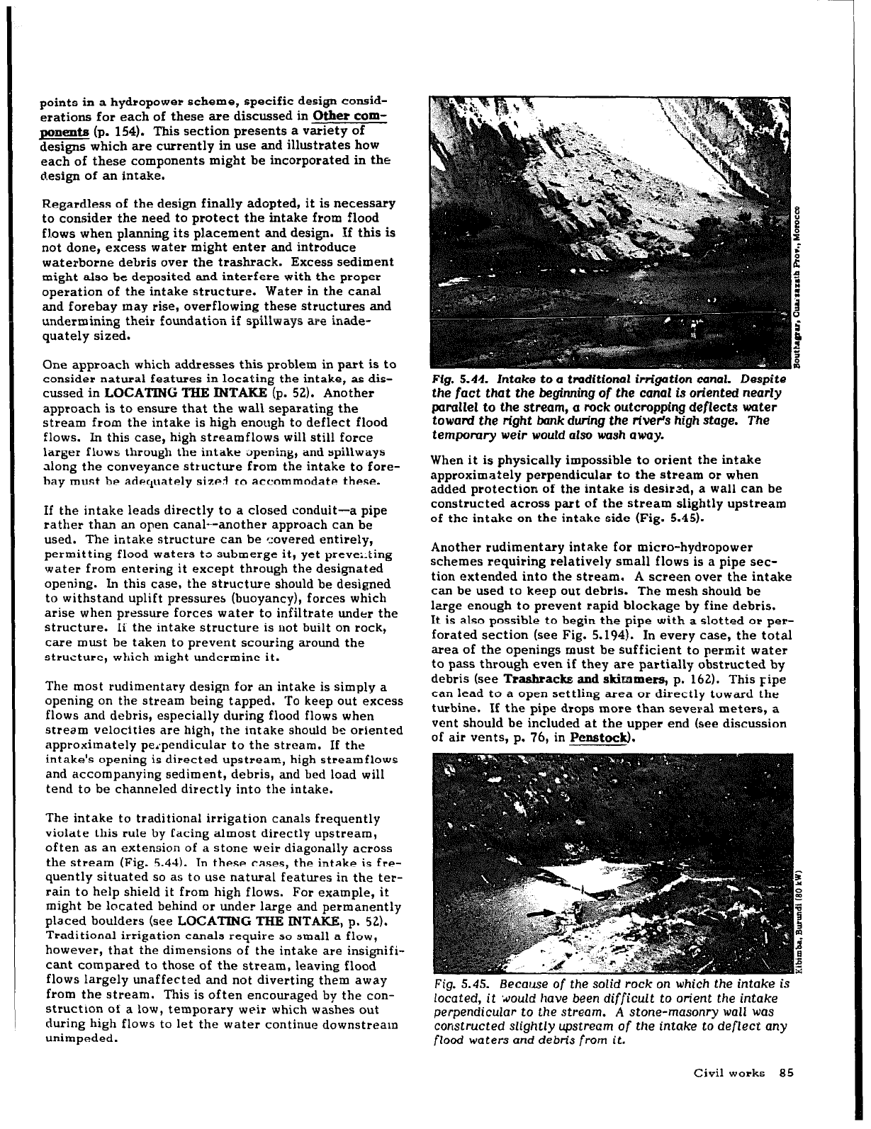
Fig. 5.44. Intake to a traditional irrigation canal. Despite
the
fact that
the beginning
of
the canal is
oriented
nearly
parallel
to the stream, a rock outcropping deflects water
toward the right brink during the river’s high
stage.
The
temporary weir would also
wash away.
I
larger flows through the intake opening, and spillways
along the conveyance structure from the intake to fore-
When it is physically impossible to orient the intake
bay must be adequately sizei co accommodate these.
approximately perpendicular to the stream
or
when
added protection of the intake is desired, a wall can be
If the intake leads directly to a closed conduit-a pipe
rather than an open canal--another approach can be
used. The intake structure can be c:overed entirely,
permitting flood waters to submerge it, yet preve::ting
water from entering it except through the designated
opening.
In this case, the structure should be designed
to withstand uplift pressures (buoyancy), forces which
arise when pressure forces water to infiltrate under the
structure. Ii the intake structure is uot built on rock,
care must be taken to prevent scouring around the
structure, which might undermine it.
The most rudimentary design for an intake is simply a
opening on the stream being tapped. To keep out excess
flows and debris, especially during flood flows when
stream velocities are high, the intake should be oriented
approximately pe,*pendicular to the stream. If the
intake’s opening is directed upstream, high streamflows
and accompanying sediment, debris, and bed load will
tend to be channeled directly into the intake.
The intake to traditional irrigation canals frequently
violate this rule by facing almost directly upstream,
often as an extension of a stone weir diagonally across
the stream (Fig. 5.44). In these cases, the intake is fre-
quently situated so as to use natural features in the ter-
rain to help shield it from high flows. For example, it
might be located behind or under large and permanently
placed boulders (see LOCATING THE INTAKE, p. 52).
Traditional irrigation canals require so small a flow,
however, that the dimensions of the intake are insignifi-
cant compared to those of the stream, leaving flood
flows largely unaffected and not diverting them away
from the stream. This is often encouraged by the con-
struction of a low, temporary weir which washes out
during high flows to let the waler continue downstream
unimpeded.
cons&ted across part of the stream slightly upstream
of the intake on the intake side (Fig. 5.45).
Another rudimentary intake for micro-hydropower
schemes requiring relatively small flows is a pipe sec-
tion extended into the stream. A screen over the intake
can be used to keep out debris. The mesh should be
large enough to prevent rapid blockage by fine debris.
It is also possible to begin the pipe with a slotted or per-
forated section (see Fig. 5.194). In every case, the total
area of the openings must be sufficient to permit water
to pass through even if they are partially obstructed by
debris (see Trashracks and skimmers, p. 162). This ripe
can lead to a open settling area or directly toward the
turbine. If the pipe drops more than several meters, a
vent should be included at the upper end (see discussion
of air vents, p. 76, in Penstock).
Fig. 5.45. Because of
the solid
rock
on which
the
intake is
located, it would have
been
difficult to orient the intake
perpendicular to the stream. A stone-masonry wall was
constructed slightly upstream of the intake to deflect any
flood waters and debris
from it.
Civil works 85
I
Because this simple pipe intake requires that all points
along the pipe be below water level, some excavation
will be necessary. If this is not possible because the
stream flows over bedrock or because the water is to be
t&en over an existing dam or weir, a siphon intake
can
be used. In this case, the outlet of the pipe must be
lower in elevation than the inlet for the siphon to func-
tion. A siphon intake generally leads directly into the
penstock; therefore, debris and sediment must be
removed before they enter the siphon. A trashrack or
screen should be provided at the inlet to the siphon to
remove floating debris. The pond or body of water
behind a dam or weir in which the inlet to the siphon is
placed serves as a settling basin to remove the sediment
carried by the incoming stream. Because an air vent is
not possibie with a siphon intake, it is essentiai that the
inlet never be obstructed during operation of the siphon.
In add=, the lift through a siphon is limited to
several meters because greater heads can lead to col-
lapse of the pipe. Air valves (p. 76) describes the max-
imum safe head which can be accommodated by unrein-
forced pipe.
A major disadvantage of a siphon intake is that some
means must be found to evacuate air in the siphon to
initiate and maintain its operation. For larger schemes,
a vacuum pump connected to the high point of the
siphon performs this function. Flow to the turbine is
then cut simply by permitting air to re-enter the siphon
through a valve at this point. For small schemes where
a vacuum pump would be too costly, both ends of the
pipe can be closed temporarily while water is poured in
through an opening at the peak of the siphon. When the
pipe has been filled completely, the opening at the peak
is closed and the inlet to the pipe reopened. The siphon
is then primed and ready for operation as soon as the
lower end of the pipe is opened.
One component which is frequently included even with a
rudimentary intake to a canal is a gate (p, 154) to con-
trol ot stop the flow of water (Fig. 5.46). The flow into
a canal might have to be stopped when the turbine is not
Fig. 5.46. Only a simple gate Is fncorpamted
at thls Intake
Co a canal.
in use, when the intake, canal, forebay, ot pcnstock is
being cleaned or repaired, ot during flood flows to pre-
vent potential damage if the scheme has not been
designed to withstand them. The intakes shown in
Fig. 5.47.
‘These intakes to
two hydropower schemes
in
Papua New Guinea Incorpomte
only
gates. In
the
iltustm-
tion at
the left, the smal1 dry-season flow flowing crt
the
right is diverted toward a well-shielded intake by
a
tern/W-
rary
stone weir
(also see Fig. 5.31). In the illustration at
the right,
small
gates pivoted
along their lower edge con-
trol water admitted at tight
angle to the
streamflow
(also
see Fig. 5.32).
86 civil works
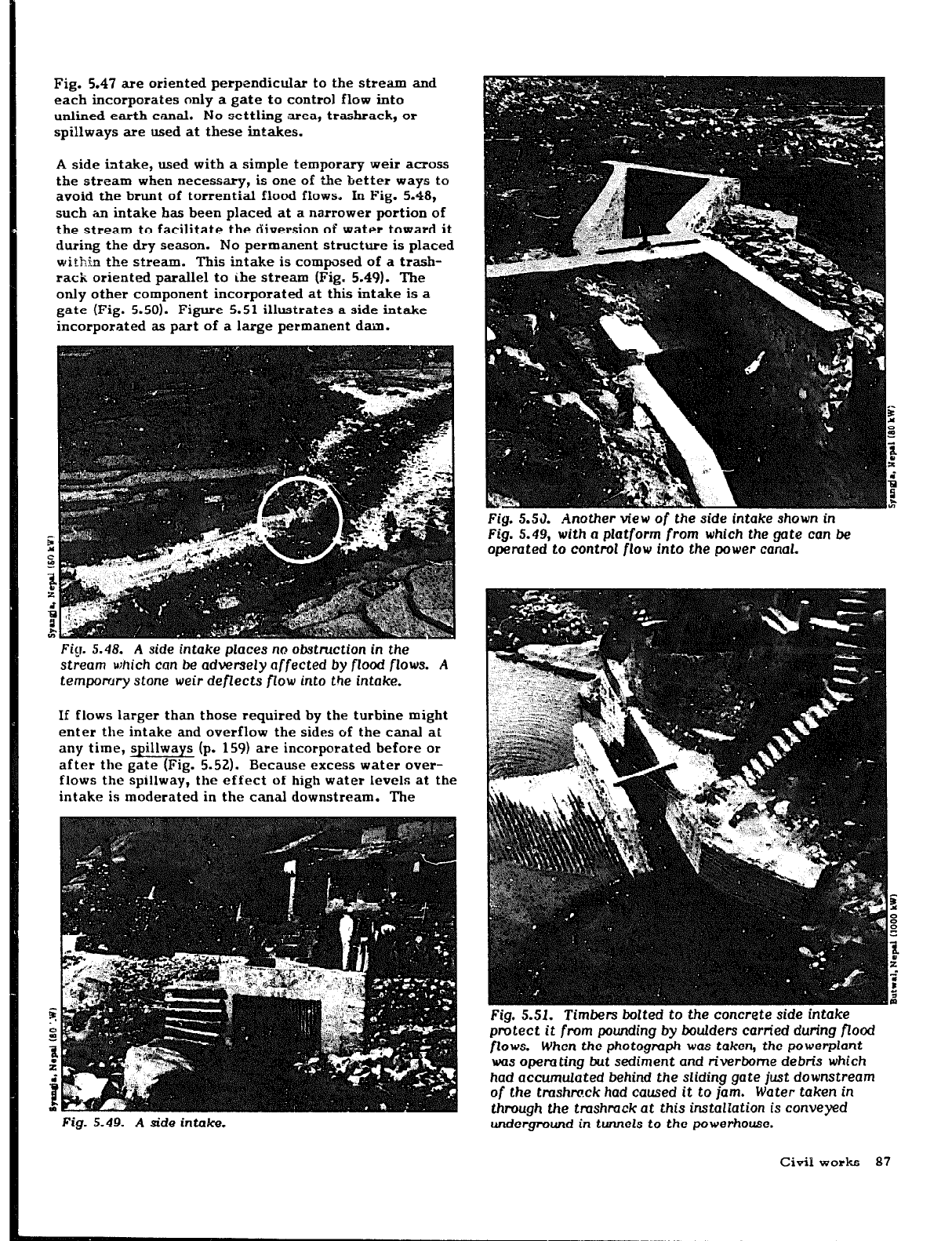
Fig. 5.47 are oriented perpendicular to the stream and
each incorporates only a gate to control flow into
unlined earth canal. No settling atea, trashrack, or
spillways are used at these intakes.
A side intake, used with a simple temporary weir aaoss
the stream when necessary, is one of the better ways to
avoid the brunt of torrential flood flows. In Fig. 5.48,
such an intake has been placed at a narrower portion of
the stream to facilitate the diversion of water toward it
during the dry season. No permanent structure is placed
within the stream. This intake is composed of a trash-
rack oriented parallel to ihe stream (Fig!. 5.49). The
only other component incorporated at this intake is a
gate (Fig. 5.50). Figure 5.51 illustrates a side intake
incorporated as part of a large permanent dam.
Fig. 5.53. Another view
of the
side intake shown in
Fig. 5.49, with a platform
from
which the gate
can be
opemted to control flow into the power canal.
Fig. 5.48. A side intake places no obstruction in
the
stream which can
be
adversely affected by flood flows. A
temporary
stone
weir
deflects
flow into the intake.
If flows larger than those required by the turbine might
enter the intake and overflow the sides of the canal at
any time, spillways (p. 159) ate incorporated before or
after the gate (Fig. 5.52). Because excess water ovet-
flows the spillway, the effect of high water levels at the
intake is moderated in the c*anal downstream. The
Fig. 5.49. A side intake.
Fig.
5.51.
Timbers
bolted
to the concrete side intake
protect
it from
pounding by boulders carried during floazl
flows.
When the photograph was taken,
the powerplant
was operating
but
sediment and riverbome debris which
had accumulated behind the sliding gate just downstream
of
the tmshmck had caused it to jam. Water taken
in
through
the tmshmck at this installation is conveyed
underground in tunnels to the
powerhouse.
Civil works 87
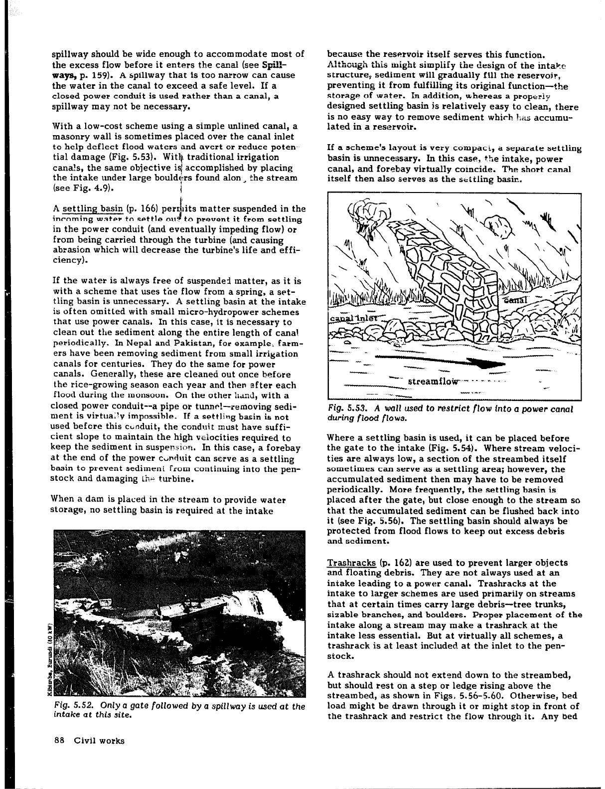
spillway should be wide enough to accommodate most of
the excess flow before it enters the csnal (see Spill-
ways,
p. 159). A spillway that is too narrow can cause
the water in the canal to exceed a safe level. If a
closed power conduit is used rather than a canal, a
spillway may not be necessary.
With a low-cost scheme using a simple unlined canal, a
masonry wall is sometimes placed over the canal inlet
to help deflect flood waters and avert or reduce poten-
tial damage (Fig. 5.53). With traditional irrigation
cana!,s, the same objective isi accomplished by placing
the intake under large bouldt;rrs found alon ~ the stream
(see Fig. 4.9).
1
A settling basin (p. 166) perrlits matter suspended in the
i
incoming water to settle oul to prevent it from settling
in the power conduit (and eventually impeding flow) or
from being carried through the turbine iand causing
abrasion which will decrease the turbine’s life and effi-
ciency).
If the water is always free of suspended matter, as it is
with a scheme that uses the flow from a spring, a set-
tling basin is unnecessary. A settling basin at the intake
is often omitted with small micro-hydropower schemes
that use power canals. In this case, it is necessary to
clean out the sediment along the entire length of
cana!
periodically. In Nepal and Pakistan, for example., farm-
ers have been removing sediment from small irrigation
canals
for
centuries. They do the same for power
canals.
Generally, these are cleaned out once before
the rice-growing season each year and then efter each
flood during the monsoon. On the other Lnd, with a
closed power conduit--a pipe or tunnel-removing sedi-
ment is virtua;!v impossible. If a settling basin is not
used befcre this cbnduit, the conduit must have suffi-
cient slope to maintain the high velocities required to
keep the sediment in suspension;. In this case, a forebay
at the end of the power cYnduit can serve as a settling
basin to prevent sediment from continuing into the pen-
stock and damaging ths turbine.
When a dam is placed in the stream to provide water
storage, no settling basin is required at the intake
Fig. 5.52. Only a gate followed
by a
spillway is used at the
intake at this site.
because the reservoir itself serves this function.
Although this might simplify the design of the intake
structure,. sediment will gradually fill the reservoir,
preventing it from fulfilling its original function-the
storage
of
water.
Xn addition, whereas a properly
designed settling basin is relatively easy to clean, there
is no easy way to remove sediment which ?ZLS: accumu-
lated in a reservoir.
If a scheme’s layout is very compaci, a separate settling
basin is unnecessary. In this case, the intake, power
canal, and forebay virtually coincide. The short canal
itself then also serves as the stitling basin.
I
“~streamfloiir-- .- - -. .
--...
---
..- -
Fig.
5.53. A wall used to
restrict
flow into a power canal
during flood flows.
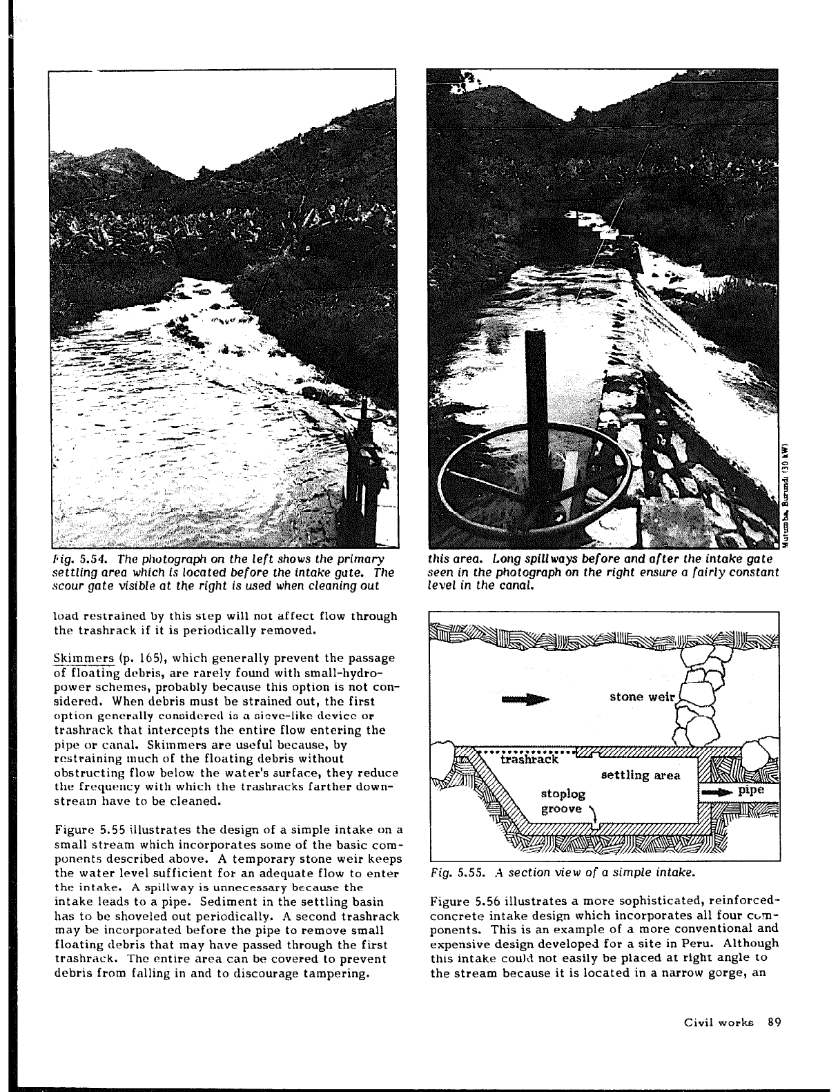
Where a settling basin is used, it can be placed
before
the gate to the intake (Fig. 5.54). Where stream veloci-
ties are always low, a section
of
the streambed itself
sometimes can serve as a settling area; however, the
accumulated sediment then may have to be removed
periodically. More frequently, the settling basin is
placed after the gate, but close enough to the stream so
that the accumulated sediment can be flushed back into
it (see Fig. 5.56). The settling basin should always be
protected from flood flows to keep
out
excess debris
and sediment.
Trashracks (p. 162) are used to prevent larger objects
and floating debris. They are not always used at an
intake leading to a power canal. Trashracks at the
intake to larger schemes are used primarily on streams
that at certain times carry large debris-tree trunks,
sizable branches, and boulders. Proper placement of the
intake along a stream may make a trashrack at the
intake less essential. But at virtually all schemes, a
trashrack is at least included at the inlet to the pen-
stock.
A trashrack should not extend down to the streambed,
but should rest on a step or ledge rising above the
streambed, as shown in Figs. 5.56-5.60. Otherwise, bed
load might be drawn through it or might stop in front of
the trashrack and restrict the flow through it. Any bed
88 Civil works
pig. 5.54. The photograph
on
the left shows the primary
settling area which is located before the intake gute. The
scour gate visible at the right is used when cleaning out
load restrained by this step will not affect flow through
the trashrack if it is periodically removed.
Skimmers (p. 1651, which generally prevent the passage
-------Y--
of floating debris, are rarely found with small-hydro-
power schemes, probably because this option is not con-
sidered. When debris must be strained out, the first
option generally considered is a sieve-like device or
trashrack that intercepts
the
entire flow entering the
pipe or canal. Skimmers are useful because, by
restraining much of the floating clebris without
obstructing flow below the water’s
surface,
they reduce
the frequency with which the trashracks farther down-
stream have to be cleaned.
Figure 5.55 illustrates the design of a simple intake on a
small stream which incorporates some of the basic com-
ponents described above. A temporary stone weir keeps
the water level sufficient for an adequate flow to enter
the intake. A spillway is unnecessary because the
intake leads to a pipe. Sediment in the settling basin
has to be shoveled out periodically. A second trashrack
may be incorporated before the pipe to remove small
floating debris that may have passed through the first
trashrack. The entire area can be covered to prevent
debris from falling in and to discourage tampering.
this area. Long spillways
before and
arter the intake gate
seen
in the photograph
on
the right
ensure
a fairly constant
level in
the
canal.
stone weir
R
Fig. 5.55. A section view
of
a simple intake.
Figure 5.56 illustrates a more sophisticated, reinforced-
concrete intake design which incorporates all four cbm-
ponents. This is an example of a more conventional and
expensive design developed for a site in Peru. Although
this intake could not easily be placed at right angle to
the stream because it is located in a narrow gorge, an
Civil works 89