Inversin R. Allen Micro-hydropower Sourcebook
Подождите немного. Документ загружается.

Unlike most of the other components, the power Conduit
is not an essential part of every hydropower scheme.
Where the drop in elevation is concentrated near the
powerhouse and there is a significant horizonal distance
between the intake on the stream and this drop, a power
conduit is used to reduce the cost of the civil works.
Rather than using a costly penstock pipe for the entire
distance, a power conduit conveys the water from the
intake to a point as close to above the powerhouse a
possible. The design objective is to make the penstock
as steep as possible to reduce the diameter and length-
and therefore the cost-of the required penstock pipe.
The cost OL the conduit itself mubt then be added, but
the conduit frequently can be constructed at a fraction
of the cost
of
a penstock, especially if local materials
rather than imported steel, concrete, or plastic pipe can
be used.
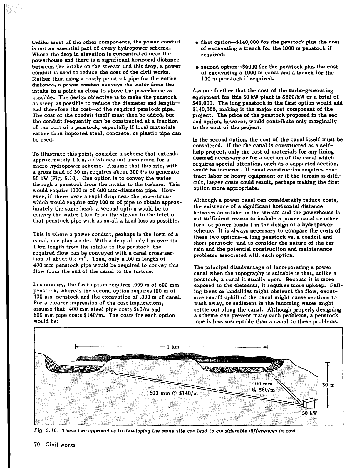
To illustrate this point, consider a scheme that extends
approximately 1 km, a distance not uncommon for a
micro-hydropower scheme. Assume that this site, with
a gross head of 30 m, requires about 300 C/s to generate
50 kW (Fig. 5.10). One option is to convey the water
through a penstock from the intake to the turbine. This
would require 1000 m of 600 mm-diameter pipe. How-
ever, if there were a rapid drop near the powerhouse
which would require only 100 m of pipe to obtain approx-
imately the same head, a second option would be to
convey the water 1 km from the stream to the inlet of
that penstock pipe with as small a head loss as possible.
This is where a power conduit, perhaps in the form of a
canal, can play a
role.
With a drop of only 1 m over its
I km length from the intake to the penstock, the
required flow can b
f
conveyed with a canal cross-sec-
tion of about 0.2 m .
Then, only a 100 m length of
400 mm penstock pipe would be required to convey this
flow from the end of the canal to the turbine.
In summary, the first option requires 1000 m of 600 mm
penstock, whereas the second option requires 100 m of
400 mm penstock and the excavation of 1000 m of canal.
For a clearer impression of the cost implications,
assume that 400 mm steel pipe costs $60/m and
600 mm pipe costs $140/m. The costs for each option
would be:
l
first option-$140,000 for the penstock plus the cost
of excavating a trench for the 1000 m penstock if
required;
l
second option-$6000 for the penstock plus the cost
of excavating a 1000 m canal and a trench for the
100 m penstock if
required.
Assume further that the cost of the turbo-generating
equipment for this 50 kW plant is $BOO/kW or a total of
$40,000. The long penstock in the first option would add
$140,000, making it the major cost component of the
project. The price of the penstock proposed in the sec-
ond option, however, would contribute only marginally
to the cost of the project.
In the second option, the cost of the canal itself must be
considered. If the the canal is constructed as a self-
help project, only the cost of materials for any lining
deemed necessary
or
for a section of the canal which
requires special attention, such as a supported section,
would be incurred. If canal construction requires con-
tract labor or heavy equipment or if the terrain is diffi-
cult, larger costs could result, perhaps making the first
option more appropriate.
Although a power canal can considerably reduce costs,
the existence of a significant horizontal distance
between an intake on the stream and the powerhouse is
not sufficient reason to include a power canal or other
form of power conduit in the design of a hydropower
scheme. It is always necessary to compare the costs of
these two options--a long penstock
vs.
a conduit and
short penstock-and to consider the nature of the ter-
rain and the potential construction and maintenance
problems associated with each option.
The principal disadvantage of incorporating a power
canal when the topography is suitable is that, unlike a
penstock, a canal is usually open. Because it is more
exposed to the elements, it requires more upkeep. Fall-
ing trees or landslides might obstruct the flow, exces-
sive runoEf uphill of the canal might cause sections to
wash away, or sediment in the incoming water might
settle out along the canal. Although properly designing
a scheme can prevent many such problems, a penstock
pipe is less susceptible than a canal to these problems.
1 km
4
Fig. 5.10. These two approaches to developing the some site can lead to
constdembk differences in
cO3t.
70 Civil works
As mentioned, a low-pressure pipe can also serve as a
power conduit. This avoids some of the disadvantages
of using an open canal. By using a low-pressure conduit,
especially at medium- and high-head sites, a less costly
pipe can be used because a pipe wall thinner than that
used for the pressure penstock is necessary. A low-
pressure conduit generally will cost more than an earth
canal.
Because power canals are the most commonly used form
of power conduit,
Power
conduits (p. 96) deals primarily
with their design and construction; however, some
information on the use of pipes as power conduits is also
included.
Depending on the length, slope, and dimensions of the
power canal, spillways (p. 159) might be incorporated at
appropriate intervals. When they are used, provisions
must be made to ensure that any overflow leaving via
the spillways will not undermine the canal or other
components. Spillways are necessary if there is any
chance that a canal might overflow if excess water
enters the canal, although proper design of the intake
should minimize this possibility. Spillways are also
necessary if dirt from landslides or other debris entering
a canal could restrict the flow, causing water to back up
until the canal overflows.
If a canal is built on a hillside where runoff along with
debris and sediment can enter the canal, provision may
have to be made for proper drain= (p. 108) around the
___
canal. If significant runoff can still enter a canal, a
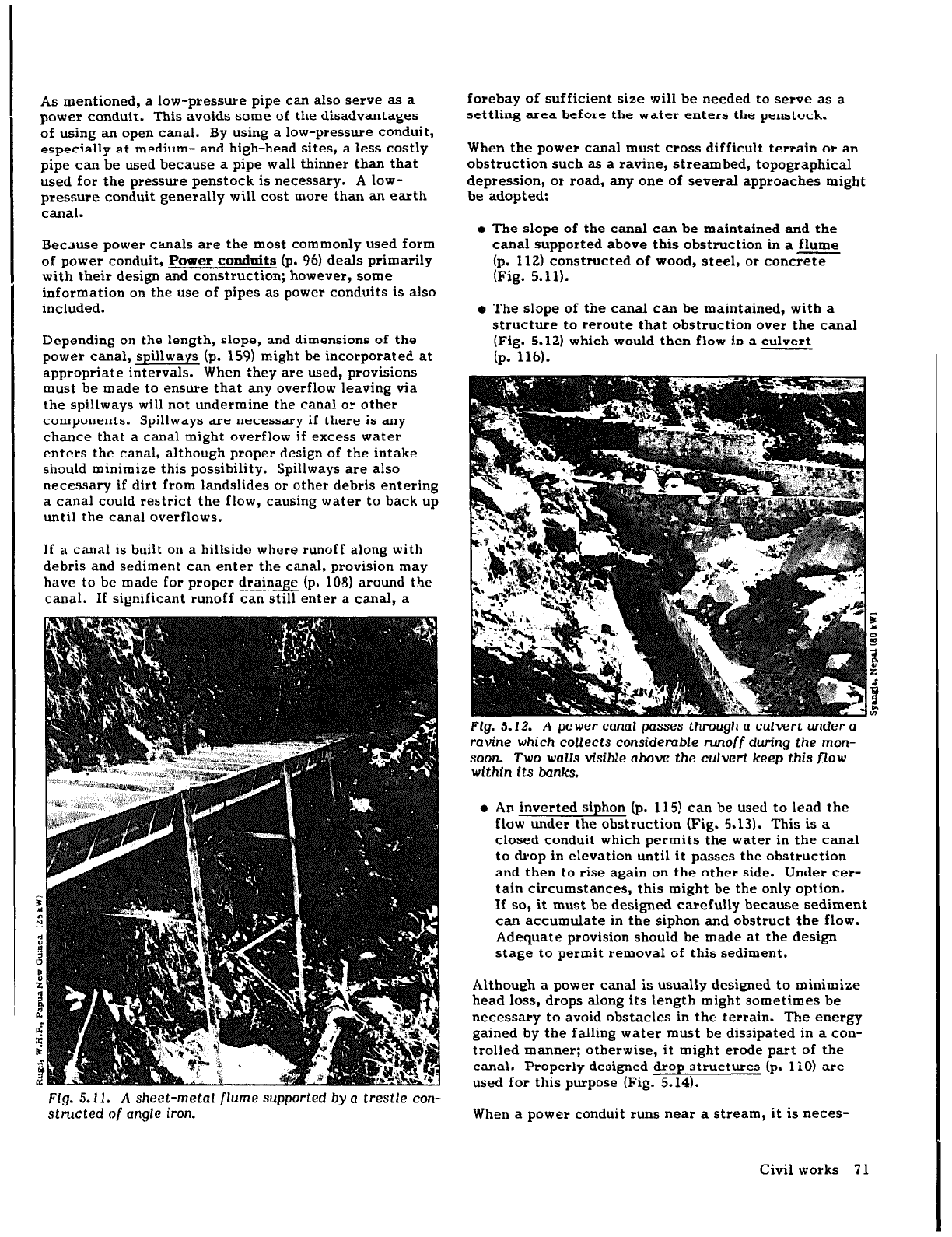
Fig. 5.11. A sheet-metal
flume
supported by
a
trestle con-
structed of angle iron.
forebay of sufficient size will be needed to serve as a
settling area before the water enters the penstock.
When the power canal must cross difficult terrain or an
obstruction such as a ravine, streambed, topographical
depression, or road, any one of several approaches might
be adopted:
e The slope
of
the canal can be maintained and the
canal supported above this obstruction in a flume
(p. 112) constructed of wood, steel, or concrete
(Fig. 5.11).
o The slope of the canal can be maintained, with a
structure to reroute that obstruction over the canal
(Fig. 5.12) which would then flow in a culvert
(p. 116).
Fig. 5.12. A power
canal
passes through a culvert under a
ravine which collects considerable
runoff during
the mon-
soon Two walls visible above the culvert keep this flow
within its banks.
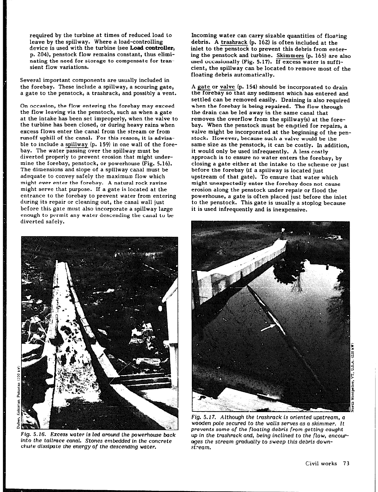
e An inverted siphon (p. 115) can be used to lead the
flow under the obstruction (Fig. 5.13). This is a
closed conduit which permits the water in the canal
to drop in elevation until it passes the obstruction
and then to rise again on the other side. Under cer-
tain circumstances, this might be the only option.
If so, it must be designed carefully because sediment
can accumulate in the siphon and obstruct the flow.
Adequate provision should be made at the design
stage to permit removal of this sediment.
Although a power canal is usually designed to minimize
head loss, drops along its length might sometimes be
necessary to avoid obstacles in the terrain. The energy
gained by the falling water must be dissipated in a con-
trolled manner; otherwise, it might erode part of the
canal. Properly designed drop structures (p. 1 i0) are
used for this purpose (Fig. 5.14).
When a power conduit runs near a stream, it is neces-
Civil works 71
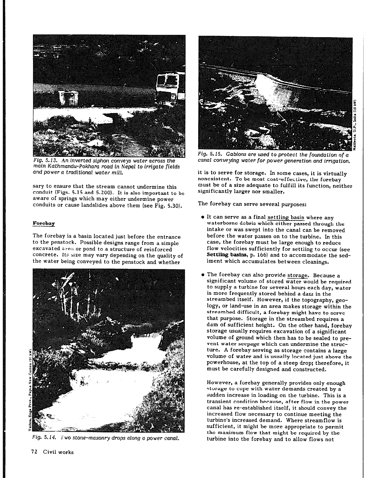
Fig. 5.13. An inverted siphon conveys water
across the
main Kathmandu-Pokham road in Nepal to irrigate fields
and power a traditional water mill.
sary to ensure that the stream cannot undermine this
conduit (Figs. 5.15 and 5.200). It is also important to be
aware of springs which may either undermine power
conduits or cause landslides above them (see Fig. 5.30).
Forebap
The forebay is a basin located just before the entrance
to the penstock. Possible designs range from a simple
excavated 6:~ or pond to a structure of reinforced
concrete. Its size may vary depending on the quality of
the water being conveyed to the penstock and whether
Fig. 5.14. i’wo stone-masonry drops along a power canal.
Fig. 5.15. Gabions are used to protect the foundation of a
canal conveying
water
for power genemtion and irrigation.
it is to serve for storage. In some cases, it is virtually
nonexistent.
To be most cost-effective, the forebay
must be of a size adequate to fulfill its function, neither
significantly larger nor smaller.
The forebay can serve several purposes:
o It can serve as a final settling basin where any
waterborne debris which either passed through the
intake or was swept into the canal can be removed
before the water passes on to the turbine. In this
case, the forebay must be large enough to reduce
flow velocities sufficiently for settling to occur (see
Settling
basins, p. 1661 and to accommodate the sed-
iment which accumulates between cleanings.
o The forebay can also provide storage. Because a
significant volume of stored water would be required
to supply a turbine for several hours ea.ch day, water
is more frequently stored behind a dam in the
streambed itself. However, if the topography, geo-
logy, or land-use in an area makes storage within the
streambed difficult, a forebay might have to serve
that purpose. Storage in the streambed requires a
dam of sufficient height. On the other hand, forebay
storage usually requires excavation of a significant
volume of ground which then has to be sealed to pre-
vent water seepage which can undermine the struc-
ture. A forebay serving as storage contains a large
volume of water and is usually located just above the
powerhouse, at the top of a steep drop; therefore, it
must be carefully designed and constructed.
However, a forebay generally provides only enough
storage to cope with water demands created by a
sudden increase in loading on the turbine. This is a
transient condition because, after flow in the power
canal has re-established itself, it should convey the
increased flow necessary to continue meeting the
turbine’s increased demand. Where streamflow is
sufficient, it might be more appropriate to permit
the maximum flow that might be required by the
turbine into the forebay and to allow flows not
72 Civil works
required by the turbine at times of reduced load Lo
leave by the spillway. ‘Where a load-controlling
device is used with the turbine (see Iamb
controller,
p. 204), penstock flow remains constant, thus elimi-
nating the need for storage to compensate for tran-
sient flow variations.
Several important components are usually included in
the forebay. These include a spillway, a scouring gate,
a gate to the penstock, a trashrack, and possibly a vent.
On occasion, the flow entering the forebay may exceed
the flow leaving via the penstock, such as when a gate
at the intake has been set improperly, when the valve to
the turbine has been closed, or during heavy rains when
excess flows enter the canal from the stream or from
runoff uphill of the canal. For this reason, it is advisa-
ble to include a spillway (p. 159) in one wall of the fore-
bay. The water passing over the spillway must be
diverted properly to prevent erosion that might under-
mine the forebay, penstock, or powerhouse (Fig. 5.16).
The dimensions and slope of a spillway ca.aal must be
adequate to convey safely the maximum flow which
might ever enter the forebay. A natural rock ravine
might serve that purpose. If a gate is located at the
entrance to the forebay to prevent water from entering
during its repair or cleaning out, the canai wall just
before this gate must also incorporate a spillway large
enough to ptarmit any water descending the canal to be
diverted safely.
Fig. 5.16. Excess water is led around the powerhouse back
into the tailmce canal.
Stones
embedded in the concrete
chute dissipate the
energy of the descendfng water.
Incoming water can carry sizable quantities of floating
debris. A trashrack (p. 162) is often included at the
inlet to the penstock to prevent this debris from enter-
ing the penstock and turbine. Skimmers (p. 165) are also
used occasionally (Fig. 5.17). If excess water is suffi-
cient, the spillway can be located to remove most of the
floating debris automatically.
A gate or valve (p. 154) should he incorporated to drain
the forebay so that any sediment which has entered and
settled can be removed easily. Draining is also required
-hen the forebay is being repaired. The flow through
the drain can be led away in the same canal that
removes the overflow from the spillway(s) at the fore-
bay. When the penstock must be emptied for repairs, a
valve might be incorporated at the beginning of the pen-
stock. However, because such a valve would be the
same size as the penstock, it can be costly. In addition,
it would only be used infrequently. A less costly
approach is to ensure no water enters the forebay, by
closing a gate either at the intake to the scheme or just
before the forebay (if a spillway is located just
upstream of that gate). To ensure that water which
might unexpectedly enter the forebay does not cause
erosion along the penstock under repair or flood the
powerhouse, a gate is often placed just before the inlet
to the penstock. This gate is usually a stoplog because
it is used infrequently and is inexpensive.
Fig. 5.17. Although the tmshrack is oriented upstream, a
wooden pole secured to the walls serves
as a skimmer. It
prevents
some
of the floating debris
from
getting
caught
up in the tmshmckand, being inclined to the
flow, encour-
ages the stream gmdualfy to sweep this debris down-
St.-earn.
Civil works 73
As is described in Penstock? an air vent (p. 76) is often
used as a safety precaution against collapse of the pen-
stock pipe. One design option would be to incorporate
this pipe in the wall of the forebay just below the inlet
to the penstock (see Fig. 5.109).
If a second penstock and turbine may be added at some
later date, its installation would be facilitated by incor-
porating a wooden plug in the concrete forebay wall,
possibly with a steel plate on the inside to give the
required strength. When the second penstnck is to be
installed, piercing the forebay wall will prove much
easier.
Penstock
The penstock is 3 pipe that conveys water, under pres-
sure, to the turbine. Except for some schemes with
very low head--such as open-flume Francis and propeller
turbines, in-stream turbines, and traditional water-
wheels-it is an essential part of any micro-hydropower
plant.
A penstock pipe can be installed either above
or
below
ground. Flexible, small-diameter penstocks used for
plants with very low outputs are sometimes draped over
the terrain down the hillside; however, larger-diameter
penstocks installed above the ground must be secured
properly to prevent movement which could damage the
pipe. Although this increases the cost of pcnstock con-
struction and maintenance, the alternative-excavation
for a buried pipe--might he no less costly. The installa-
tion of a penstock above ground increases its exposure
to the elements, but its accessibility also facilitates
inspection, maintenance, or repairs. Burying d penstock
may involve considerable time and expense, but it pro-
tects the pipe from the elements and from landslides,
falling rocks, brush fires, and tampering. In addition,
the compacted soil firmly secures the penstock, provid-
ing adequate anchorage for most small-diameter pipes.
A penstock above ground is subject to greater tempera-
ture variations. If the turbine is not functioning contin-
uously, these temperature variations can be pronounced,
because the moderating effect of flowing water with
fairly constant temperature is not felt. Variations in
temperature result in thermal expansion, which in turn
causes stresses in the pipe. Thermal expansion and con-
traction are greatest ior a penstock which is likely to
remain empty during construction or repair, and provi-
sion must be made to accommodate these; either the
pipe must be designed to have sufficient structural
rigidity with the help of anchors and supports or expan-
sion joints (p. 136) should be incorporated. These joints
also help protect the pipe against earth tremors and are
sometimes used to accommodate a slight misalignment
of two pipe seciiilns.
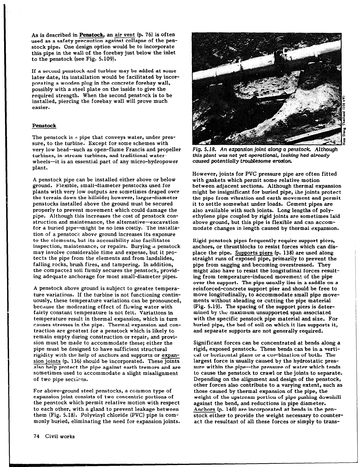
For above-ground steel penstocks, a common type of
expansion joint consists of two concentric portions of
the penstock which permit relative motion with respect
to each other, with a gland to prevent leakage between
them (Fig. 5.18). Polyvinyl chloride (PVC) pipe is com-
monly buried, eliminating the need for expansion joints.
74 Civil works
Fig.
5.18.
An expansion
joint
along a
penstock Although
this plant was
not yet opemtional, leaking had already
caused
potentially troublesome erosion
However, joints for PVC pressure pipe are often fitted
with gaskets which permit some relative motion
between adjacent sections. Although thermal expansion
might he insignificant for buried pipe, ihe joints protect
the pipe from vibration and earth movement and permit
it to settle somewhat under loads. Cement pipes are
also available with such joints. Long lengths of poly-
ethylene pipe coupled by rigid joints are sometimes laid
above ground, but this pipe is flexible and can accom-
modate changes in length caused by thermal expansion.
Rigid penstock pipes frequently require support piers,
anchors, or thrustblocks to resist forces which can dis-
place the pipe. Supports piers (p. 138) are used along
straight runs of exposed pipe, primarily to prevent the
pipe from sagging and becoming overstressed. They
might also have to resist the longitudinal forces result-
ing from temperature-induced movemeLt of the pipe
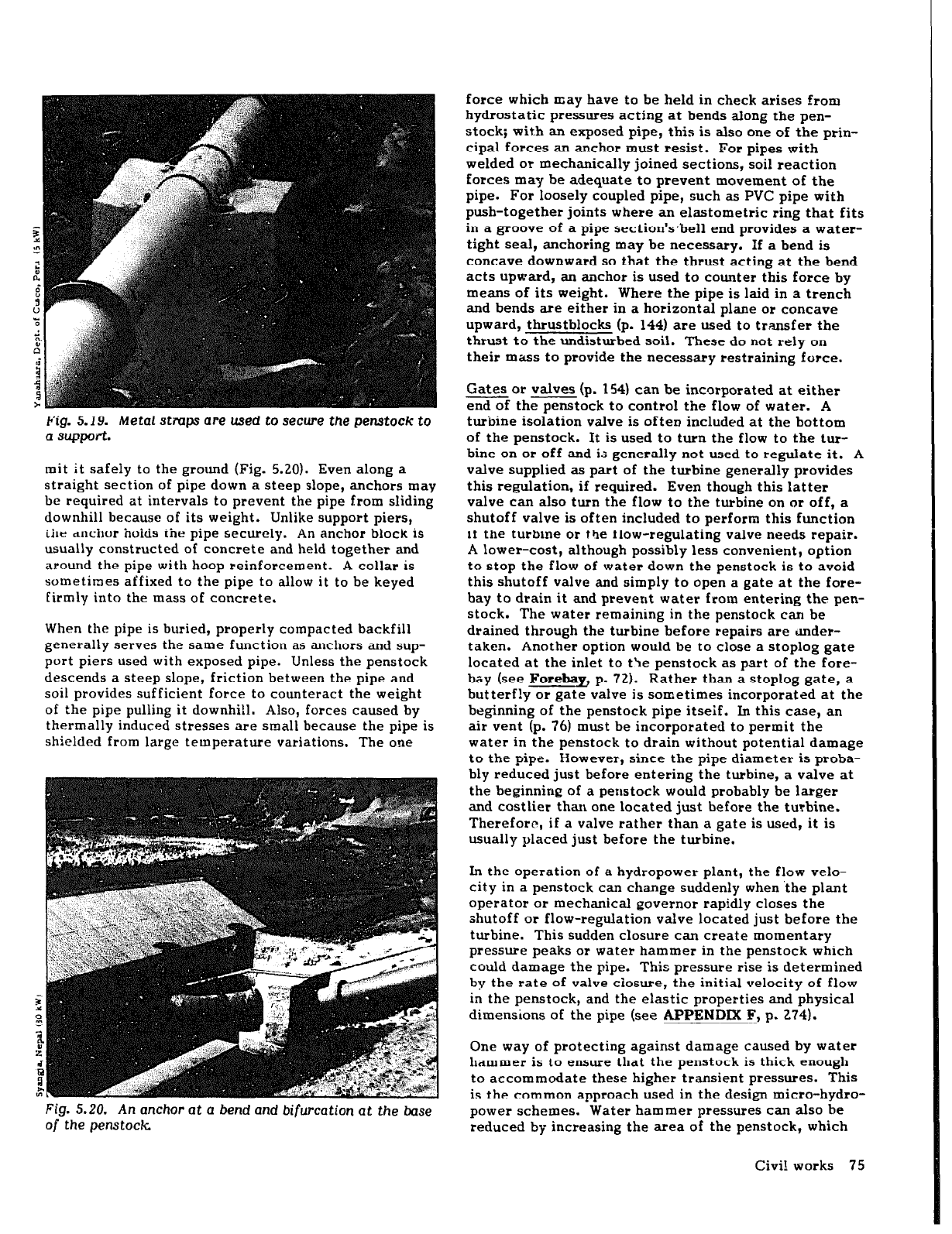
over the support. The pipe usually lies in a saddle on a
reinforced-concrete support pier and should be free to
move longitudinally, to accommodate small pipe move-
ments without abrading or cutting the pipe material
(Fig. 5.19). The spacing of the support piers is deter-
mined by the maximum unsupported span associated
with the specific penstock pipe material and size. For
buried pipe, the bed of soil on which it lies supports it,
and separate supports are not generally required.
Significant forces can be concentrated at bends along a
rigid, exposed penstock. These bends can be in a verti-
cal or horizontal plane or a combination of both. The
largest force is usually caused by the hydrostatic pres-
sure within the pipe--the pressure of water which tends
to cause the penstock to crawl or the joints to separate.
Depending on the alignment and design of the penstock,
other forces also contribute to a varying extent, such as
those caused by thermal expansion of the pipe, the
weight of the upstream portion of pipe pushing downhill
against the bend, and reductions in pipe diameter.
Anchors (p. 140) are incorporated at bends in the pen-
stock either to provide the weight necessary to counter-
act the resultant of all these forces or simply to trans-
force which may have to be held in check arises from
hydrostatic pressures acting at bends along the pen-
stock; wit.h an exposed pipe, this is also one of the prin-
cipal forces an anchor must resist. For pipes with
welded or mechanically joined sections, soil reaction
forces may be adequate to prevent movement of the
pipe. For loosely coupled pipe, such as PVC pipe with
push-together joints where an elastometric ring that fits
in a groove of a pipe section’s*bell end provides a water-
tight seal, anchoring may be necessary. If a bend is
concave downward so that the thrust acting at the bend
acts upward, an anchor is used to counter this force by
means of its weight. Where the pipe is laid in a trench
and bends are either in a horizontal plane or concave
upward, thrustblocks (p. 1441 are used to tr.ansfer the
thrust to the undisturbed soil. These do not rely on
their mass to provide the necessary restraining force.
Gates or valves (p. 1541 can be incorporated at either
--
end of the penstock to control the flow of water. A
turbine isolation valve is often included at the bottom
of the penstock. It is used to turn the flow to the tur-
bine on or off and is generally not used to regulate it. A
valve supplied as part of the turbine generally provides
this regulation, if required. Even though this latter
valve can also turn the flow to the turbine on or off, a
shutoff valve is often included to perform this function
it the turbine or the Flow-regulating valve needs repair.
A lower-cost, although possibly less convenient, option
to stop the flow of water down the penstock is to avoid
this shutoff valve and simply to open a gate at the fore-
bay to drain it and prevent water from entering the pen-
stock. The water remaining in the penstock can be
drained through the turbine before repairs are Imder-
taken. Another option would be to close a stoplog gate
located at the inlet to t’le penstock as part of the fore-
bay (see Forehay, p. 72). Rather than a stoplog gate, a
butterf!y or gate valve is sometimes incorporated at the
beginning of the penstock pipe itseif. In this case, an
air vent (p. 76) must be incorporated to permit the
water in the penstock to drain without potential damage
to the pipe. However, since the pipe diameter is proba-
bly reduced just before entering the turbine, a valve at
the beginning of a penstock would probably be larger
and costlier than one located just before the turbine.
Therefore, if a valve rather than a gate is used, it is
usually placed just before the turbine.
Fig. 5.19. Metal stmps are used to secure the penstock
to
a support.
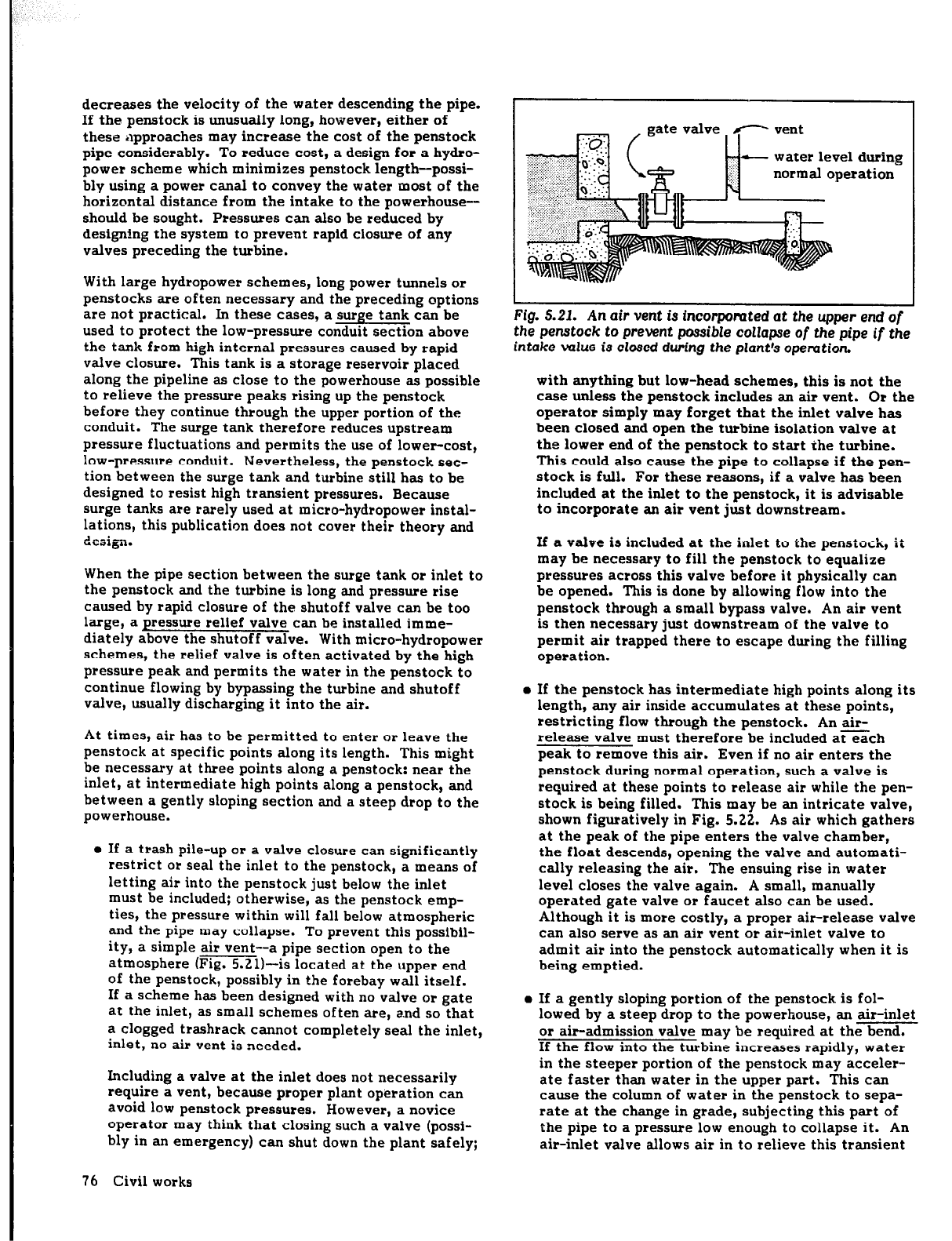
mit it safely to the ground (Fig. 5.20). Even along a
straight section of pipe down a steep slope, anchors may
be required at intervals to prevent the pipe from sliding
downhill because of its weight. Unlike support piers,
ihr
anchor holds the pipe secureiy. An anchor biock is
usually constructed of concrete and held together and
around the pipe with hoop reinforcement. A collar is
sometimes affixed to the pipe to allow it to be keyed
firmly into the mass of concrete.
When the pipe is buried, properly compacted backfill
generally serves the same function as anchors and sup-
port piers used with exposed pipe. Unless the penstock
descends a steep slope, friction between the pipe and
soil provides sufficient force to counteract the weight
of the pipe pulling it downhi!l. Also, forces caused by
thermally induced stresses are small because the pipe is
shielded from large temperature variations. The one
Fig. 5.20.
An anchor at
a bend and
bifurcation
at the base
of
the
penstock
In the operation of a hydropower plant, the flow velo-
city in a penstock can change suddenly when ‘the plant
operator or mechanical governor rapidly closes the
shutoff or flow-regulation valve located just before the
turbine. This sudden closure can create momentary
pressure peaks or water hammer in the penstock which
could damage the pipe. This pressure rise is determined
by the rate of valve ciosure, the initial velocity of flow
in the penstock, and the elastic properties and physical
dimensions of the pipe (see .APPENDIX F, p- 274).
One way of protecting against damage caused by water
hammer is to ensure that the penstock is thick enough
to accommodate these higher transient pressures. This
is the common approach used in the design micro-hydro-
power schemes. Water hammer pressures can also be
reduced by increasing the area of the penstock, which
Civil works 75
decreases the velocity of the water descending the pipe.
If the penstock is unusually long, however, either of
these ilpproaches may increase the cost of the penstock
pipe considerably. To reduce cost, a design
for
a hydra-
power scheme which minimizes penstock length-possi-
bly using a power canal to convey the water most of the
horizontal distance from the intake to the powerhouse--
should be sought. Pressures can also be reduced by
designing the system to prevent rapid closure of any
valves preceding the turbine.
With large hydropower schemes, long power tunnels or
penstocks are often necessary and the preceding options
are not practical. In these cases, a surge tank can be
used to protect the low-pressure conduit section above
the tank from high internal pressures caused by rapid
valve closure. This tank is a storage reservoir placed
along the pipeline as close to the powerhouse as possible
to relieve the pressure peaks rising up the penstock
before they continue through the upper portion of the
conduit. The surge tank therefore reduces upstream
pressure fluctuations and permits the use of lower-cost,
low-pressure conduit. Nevertheless, the penstock sec-
tion between the surge tank and turbine still has to be
designed to resist high transient pressures. Because
surge tanks are rarely used at micro-hydropower instal-
lations, this publication does
not
cover their theory and
design.
When the pipe section between the surge tank or inlet to
the penstock and the turbine is long and pressure rise
caused by rapid closure of the shutoff valve can be too
large, a pressure relief valve can be installed imme-
diately above the shutoff valve. With micro-hydropower
schemes, the relief valve is often activated by the high
pressure peak and permits the water in the penstock to
continue flowing by bypassing the turbine and shutoff
valve, usually discharging it into the air.
At times, air has to be permitted to enter or leave the
penstock at specific points along its length. This might
be necessary at three points along a penstock: near the
inlet, at intermediate high points along a penstock, and
between a gently sloping section and a steep drop to the
powerhouse.
l
If a trash pile-up or a valve closure can significantly
restrict or seal the inlet to the penstock, a means of
letting air into the penstock just below the inlet
must be included; otherwise, as the penstock emp-
ties, the pressure within will fall below atmospheric
and the pipe may collapse. To prevent this possibil-
ity, a simple air vent-a pipe section open to the
atmosphere (Fig. 5.21)--is located at the upper end
of the penstock, possibly in the forebay wall itself.
If a scheme has been designed with no valve or gate
at the inlet, as small schemes often are, and so that
a clogged trashrack cannot completely seal the inlet,
inlet, no air vent is needed.
Including a valve at the inlet does not necessarily
require a vent, because proper plant operation can
avoid low penstock pressures. However, a novice
operator may think that closing such a valve (possi-
bly in an emergency) can shut down the plant safely;
76 Civil works
-
water level during
normal operation
Fig. 5.21. An
air
vent is fncorpomtea at the upper
end of
the penstock
to
prevent possible collapse of
the
pipe
if the
intake value is closed during
the
plant’s opemtion.
with anything but low-head schemes, this is not the
case unless the penstock includes an air vent. Or the
operator simply may forget that the inlet valve has
been closed and open the turbine isolation valve at
the lower end of the penstock to start the turbine.
This could also cause the pipe to collapse if the pen-
stock is full. For these
reasons,
if a valve has been
included at the inlet to the penstock, it is advisable
to incorporate an air vent just downstream.
16
a* a valve is in&tided at the inlet to the pensto&, it
may be necessary to fill the penstock to equalize
pressures across this
valve before
it physically can
be opened. This is done by allowing flow into the
penstock through a small bypass valve. An air vent
is then necessary just downstream of the valve to
permit
air
trapped there to escape during the filling
operation.
l
If the penstock has intermediate high points along its
length, any air inside accumulates at these points,
restricting flow through the penstock. An air-
release valve must therefore be included ateach
peak to remove this air. Even if no air enters the
penstock during normal operation, such a valve is
required at these points to release air while the pen-
stock is being filled. This may be an intricate valve,
shown figuratively in Fig. 5.22. As air which gathers
at the peak of the pipe enters the valve chamber,
the float descends, opening the valve and automati-
cally releasing the air. The ensuing rise in water
level closes the valve again. A small, manually
operated gate valve or faucet also can be used.
Although it is more costly, a proper air-release valve
can also serve as an air vent or air-inlet valve to
admit air into the penstock automatically when it is
being emptied.
l
If a gently sloping portion of the penstock is fol-
lowed by a steep drop to the powerhouse, an air-inlet
or air-admission valve may be required at the bend.
If the flow into the turbine increases rapidly, water
in the steeper portion of the penstock may acceler-
ate faster than water in the upper part. This can
cause the column of water in the penstock to sepa-
rate at the change in grade, subjecting this part of
the pipe to a pressure low enough to collapse it. An
air-inlet valve allows air in to relieve this transient
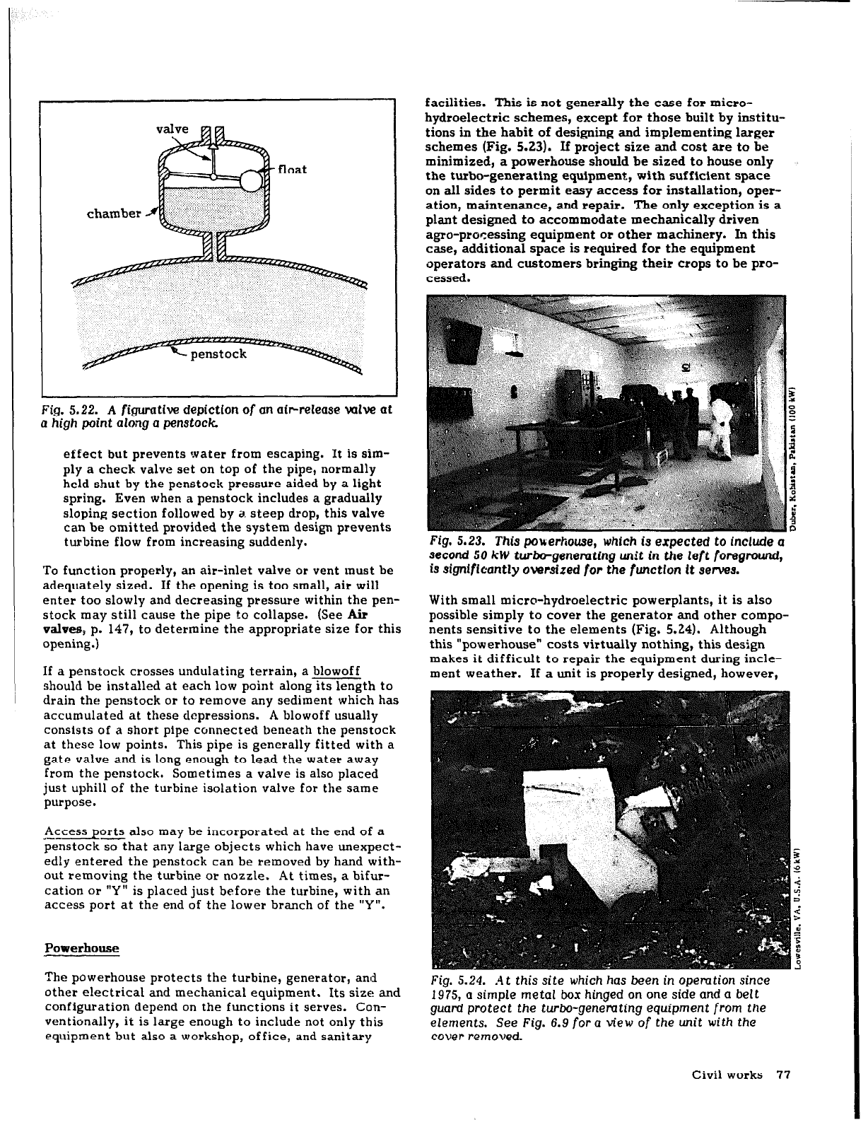
Fig. 5.22. A figurative depiction of
an air-release valve at
a high point
along
a penstock
effect but prevents water from escaping. It is sim-
ply a check valve
set on top
of the pipe, normally
held shut by the penstock pressure aided by a light
spring. Even when a penstock includes a gradually
sloping section followed by a. steep drop, this
valve
can be omitted provided the system design prevents
turbine flow from increasing suddenly.
To function properly, an air-inlet valve or vent must be
adequately sized. If the opening is too small, air will
enter too slowly and decreasing pressure within the pen-
stock may still cause the pipe to collapse. (See Air
valves, p. 147, to determine the appropriate size for this
opening. j
If a penstock crosses undulating terrain, a blowoff
should be installed at each low point alongsgth to
drain the penstock or to remove any sediment which has
accumulated at these depressions. A blowoff usually
consists of a short pipe connected beneath the penstock
at these low points. This pipe is generally fitted with a
gate valve and is long enough to lead the water away
from the penstock. Sometimes a valve is also placed
just uphill of the turbine isolation valve for the same
purpose.
-Access ports also may be incorporated at the end of a
penstockzhat any large objects which have unexpect-
edly entered the penstock can be removed by hand with-
out removing the turbine or nozzle. At times, a bifur-
cation or “Y” is placed just before the turbine, with an
access port at the end of the lower branch of the ‘Y”.
Powerhouse
The powerhouse protects the turbine, generator, and
other electrical and mechanical equipment. Its size and
configuration depend on the functions it
serves. Con-
ventionally, it is large enough to include not only this
equipment but also a workshop, office, and sanitary
facilities. This is not
generally
the case for micro-
hydroelectric schemes, except for those built by institu-
tions in the habit of designing and implementing larger
schemes (Fig. 5.23). If project size and cost are to be
minimized, a powerhouse should be sized to house only
the turbo-generating equipment, with sufficient space
on all sides to permit easy access for installation, oper-
ation, maintenance, and repair. The only exception is a
plant designed to accommodate mechanically driven
agro-processing equipment or other machinery. In this
case, additional space is required for the equipment
operators and customers bringing their crops to be pro-
cessed.
Fig. 5.23.
This pou;erhouse, which
is expected to include a
second
50 kW turbo-genemtlng unit
in the left foreground,
IS significantly oversized for the function it swvea.
With small micro-hydroelectric powerplants, it is
also
possible simply to cover the generator and other compo-
nents sensitive to the elements (Fig. 5.24). Although
this “powerhouse” costs virtually nothing, this design
makes it difficult to repair the equipment during incle-
ment weather. If a unit is properly designed, however,
Fig. 5.24. At this site which
has
been
in
opemtion since
1975, a simple metal box hinged on one side and a belt
guard protect the turbo-generating
equipment from the
elements. See Fig. 6.9 for a view
of the unit
with the
cover removed.
Civil works 77
access to the turbo-generating equipment is not fre-
quently required.
With some low-head axial-flow turbines in the bulb
con-
figuration, both the turbine and generator are located in
the water passageway (see Fig. 6.12b); only cables car-
rying the power emerge. In this case, neither power-
house nor simple cover is required. Any switchgear near
the turbo-generating equipment can be placed in a small
weatherproof enclosure.
The location of the powerhouse is as important as is its
design. For a discussion of this subject, see LOCATING
THE F’OWERHOUSE (p. 56).
head, more care is necessary because head losses can be
more significant. Flow in a tailrace canill is governed
by the same law governing flow in power canals (see
Determining canal dimensions and slope, p. 96).
DESIGN AND CONSTEXJCTION DETAaS
Dams and weks
This section emphasizes <J&s, because a majority of
micro-hydropower schemes in developing c,Iuntries only
need water to be diverted into the intake. However,
because there ix sometimes also a need for water stor-
age or for increasing head, several types of dams are
also reviewed.
Tailrace
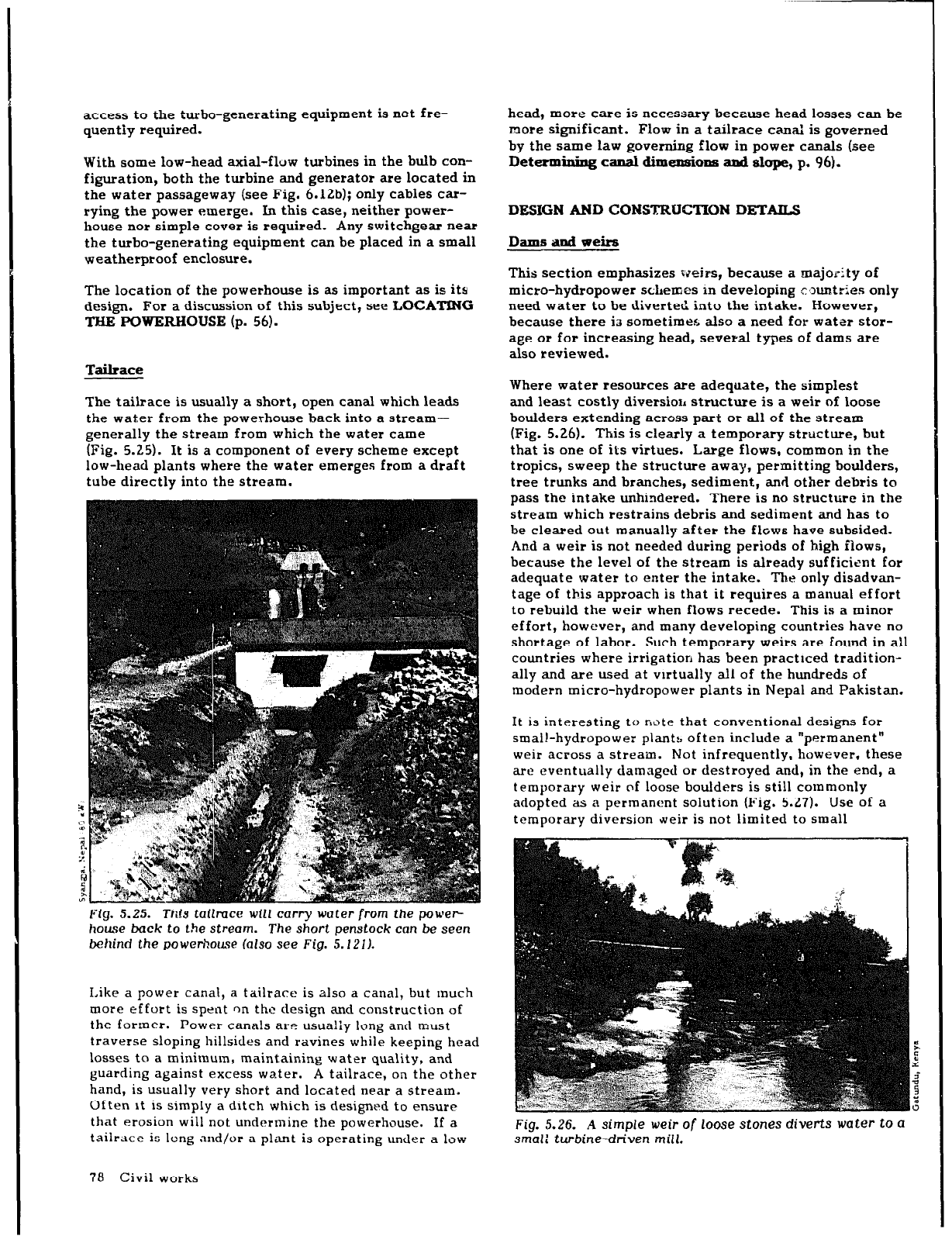
The tailrace is usually a short, open canal which leads
the water from the powerhouse back into a stream-
generally the stream from which the water came
(Fig. 5.25). It is a component of every scheme except
low-head plants where the water emerges from a draft
tube directly into the stream.
Fig. 5.25. This tailmce will carry
water from the power-
house back to the stream. The short penstock can be seen
behind the powerhouse (also see Fig. 5.1211.
Like a power canal, a tailrace is also a canal, but much
more effort is spent on the design and construction of
the former. Power canals are usualiy long and must
traverse sloping hillsides and ravines while keeping head
losses to a minimum, maintaining water quality, and
guarding against excess water. A tailrace, on the other
hand, is usually very short and located near a stream.
Often it is simply a ditch which is designed to ensure
that erosion will not undermine the powerhouse. If a
tailrace is long and/or a plant is operating under a low
Where water resources are adequate, the simplest
and least costly diversiorl structure is a weir of loose
boulders extending across part or all of the stream
(Fig. 5.26). This is clearly a temporary structure, but
that is one of its virtues. Large flows, common in the
tropics, sweep the structure away, permitting boulders,
tree trunks and branches, sediment, and other debris to
pass the intake unhindered. There is no structure in the
stream which restrains debris and sediment and has to
be cleared out manually after the flows have subsided.
An.d a weir is not needed during periods of high ilows,
because the level of the stream is already sufficient for
adequate water to enter the intake. The only disadvan-
tage of this approach is that it requires a manual effort
to rebuild the weir when flows recede. This is a minor
effort, however, and many developing countries have no
shortage of labor. Such temporary weirs are found in all
countries where irrigation has been practiced tradition-
ally and are used at virtually all of the hundreds of
modern micro-hydropower plants in Nepal and Pakistan.
It is interesting to rrotc that conventional designs for
small-hydropower plants often include a “permanent”
weir across a stream.
Not infrequently, however, these
are eventually damaged or destroyed and, in the end, a
temporary weir rrf loose boulders is still cotnmonly
adopted as a permanent solution (Fig. 5.27). Use of a
temporary diversion weir is not limited to small
Fig. 5.26. A simple weir of loose
stones
diverts water to a
smal: turbine-driven mill.
78 civil works
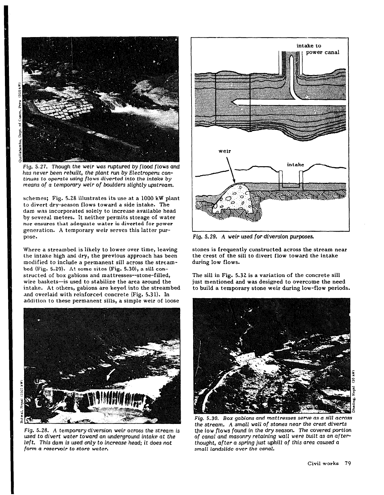
Fig. 5.27. Though the weir was ruptured
by flood flows and
has
never
been rebuilt, the plant run by Electroperu con-
tinues
to operate using flows diverted into the intake
by
means
of a temporary
weir
of boulders slightly upstream.
schemes; Fig. 5.28 illustrates its use at a 1000 kW plant
to divert dry-season flows toward a side intake. The
dam was incorporated solely to increase available head
by several meters. It neither permits storage of water
nor ensures that adequate water is diverted for power
generation. A temporary weir serves this latter pur-
pose.
Where a streambed is likely to lower over time, leaving
the intake high and dry, the previous approach has been
modified to include a permanent sill across the stream-
bed (Fig. 5.29). At some sites (Fig. 5.301, a sill con-
structed of box gabions and mattresses--stone-filled,
wire baskets-is used to stabilize the area around the
intake. At others, gabions are keyed into the streambed
ad overlaid with reinforced concrete (Fig. 5.31). In
addition to these permanent sills, a simple weir of loose
Fig. 5.28. A temporary diversion weir across the stream is
used to divert
water toward an
underground intake at the
left. This dum is used only to increase
head; it does not
form a reservoir to store water.
intake to
weir
Fig. 5.29. A weir used
for
diversion purposes.
stones is frequently constructed across the stream near
the crest of the sill to divert flow toward the intake
during low flows.
The sill in Fig. 5.32 is a variation of the concrete sill
just mentioned and was designed to overcome the need
to build a temporary stone weir during low-flow periods.
Fig. 5.30. Box
gabions and mattresses serve as a sill
across
the stream. A small wall of stones near the crest diverts
the low flows found in the dry season. The covered portion
of canal and masonry retaining wall were built as an after-
thought, after a spring just uphill
of
this area caused a
small landslide over the canal.
Civil works 79