Kothari D.P., Nagrath I.J. Modern Power Systems Analysis
Подождите немного. Документ загружается.

ffifftl|
Modern
Power
svstem nnarys,s
lEtllvl
P,
=
u, #
sin
d-
P**
sind
,
ndT^e
Under steady
operating
condition
P.o
=
Pro
=
P** sin
do
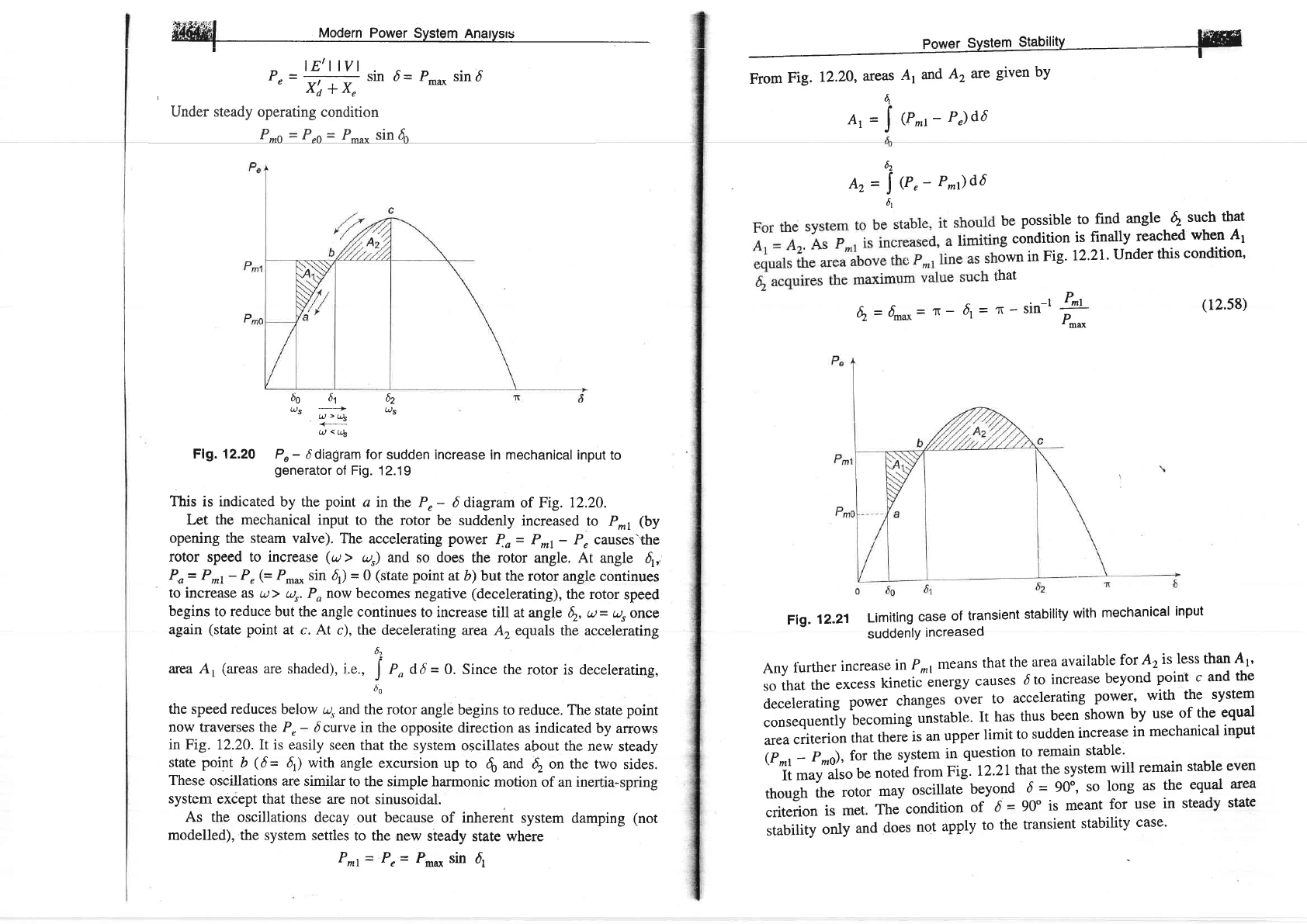
Flg. 12.20
P"-
6 diagram for
sudden increase
in mechanical input
to
generator
of Fig.
12.19
This
is
indicated
by the
point
ainthe
Pr-
6
diagram
of Fig.
12.20.
Let the
mechanical
input
to the
rotor be
suddenly increased
to Pn
(by
opening
the
steam
valve).
The
accelerating
power
1o
=
P*t
-
P, causes'the
rotor
speed
to increase
(u>
a,,r) and
so does
the rotor
angle.
At
angle
6r,,
Po= P*r- Pr(=
P-* sin
4)
=
O
(state
point
atb)but
the rotor angle
continues
to increase
as t., ) ur.Po
now becomes
negative
(decelerating),
the rotor
speed
begins
to reduce but the angle
continues
to increase
till at angle
6.,
a=
ur once
again
(state
point
at c.
At c), the-decelerating
area
A, equals
the accelerating
bc
area A,
(areas
are
shaded),
j.e.,
J
,, Od
=
0. Since the
rotor is decelerating,
6o
the
speed
reduces
below ur and
the rotor
angle begins
to reduce.
The state
point
now
traverses the P,
-
6 curve
in the opposite
direction
as indicated
by arrows
in
Fig. 12.20.It is
easily seen
that the system
oscillates about
the new
steady
state
point
b
(6=
4)
with angle
excursion
up to
6
*d
4.on
the two
sides.
These
oscillations
are similar to
the simple
harmonic motion
of an inertia-spring
system
except that these
are not sinusoidal.
As the
oscillations decay
out because
of inherent
system damping
(not
modelled),.the system
settles
to the new
steady
state where
P^t
=
P,
=
Prn.* sin
dl
6bfi62
%
?'i
('s
Q
<(4
4n
Ar=)(Pn-P")d6
Az=i<r,-P^)d6
6l
be
possible
to
find
angle
d2
such
that
rg
condition
is
finally
reached
when
41
own
in
Fig.l2.2L
Under
this
condition,
hat
6.
=
6^o=
T
-
6t=
n'-sin-l
+:
(12.58)
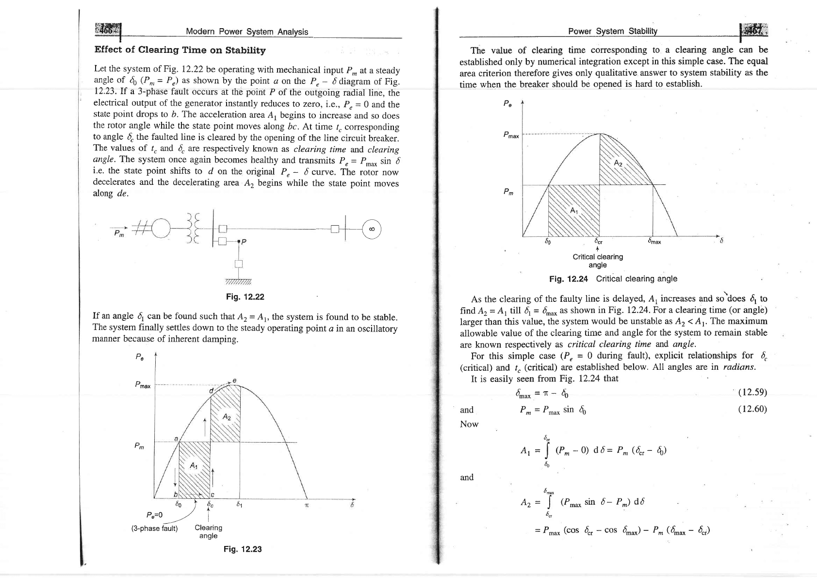
Fig.
12.21
Limiting
case
of
transient
stability
with
mechanical
input
suddenlY
increased
Any
turther
increas
e in
P
^,
means
that
the
area
available
for
A,
is
less
than
A1'
so
that
the
excess
kinetic
energy
causes
d
to
increase
beyond
point
c
and
the
decelerating
power
changes
over
to
accelerating
power,
with
the
system
consequently
becoming
uistable.
It
has
thus
been
shown
by
use
of
the
equal
area
criterion
that
there-is
an
upper
limit
to
sudden
increase
in
mechanical
input
(P^r-
Po,s),
for
the
system
in
question
to
remain
stable'
'
'ii
',,uy'ulso
be
not"i
from
Fig.
12.21that
the system
will
remain
stable
even
though
the
rotor
may
oscillate
beyo-nd
-{^=.90"'
so
long
as
the
equal
area
criterion
is
met.
The
condition
of
d
=
90"
is meant
for
use
in
steady
state
stability
only
and
does
not
apply
to
the
transient
stability
case'
trs#ffi r._r_..._ A
{i..fuu.xdr
ruooern
Fower
uvslem
Anarvsrs
-
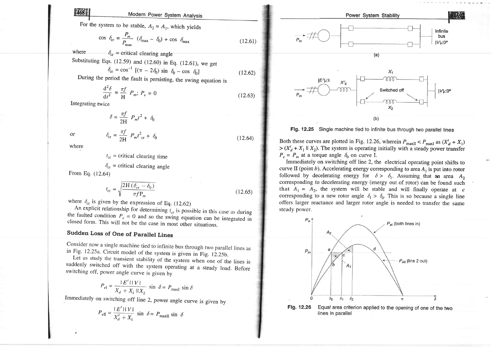
Effect
of
Clearing
Time
on Stability
Let the
system
of Fig.
12.22
be
operating
with
mechanical
input
P^ at a
steady
angle
of
d0
(Pn,=
P") as
shown
by
the
point
a
on the
Pr-
6 cliagram
of Fig.
12.23.If
a 3-phase
fault
occurs
at the
point
P
of the
outgoing
radial
line, the
electrical
output of
the
generator
instantly
reduces
to zero,
i.e,,
p,
=
0
and
the
state
point
drops
to b. The
acceleration
area
A, begins
to increase
and so does
the
rotor
angle
while the
state point
moves
along
bc.
At time
/. corresponding
to angle
6, the faulted
line
is
cleared
by the
opening
of the
line
circuit
breaker.
The
values
of /,
attd
4
are
respectively
known
as clearing
time
and,
clearing
angle. The
system
once again
becomes
healthy
and
transmits
p,
=
p,ou,.
sin
d
i.e.
the
state
point
shifts
to
d on
the original
P,
-
d curve.
The
rotor now
decelerates
and
the decelerating
area
A, begins
while the
state
point
moves
along
de.
F19.12.22
If an
angle
fi
can be found
such
that A2=
Ap
the
system
is found
to be
stable.
The
systern
finally
settles down
to
the steady
operating point
a rn
an
oscillatory
manner
because
of inherent
damping.
| /'-\
-ll\
|-t___j
co
)
-l
\-/
Pe
D
,
max
Pm
6elf."
P"=o
-.--/
i
(3-phase
fault)
Clearing
61
angle
Fig. 12.23
l':fiffn#;i;
Power a
t
rresponding to
a clearing angle can
be
established
only
by numerical
integration except
in this simple
case. The equal
area
criterion
therefore
gives
only
qualitative
answer to system
stability
as the
time
whgn
the breaker
should
be opened
is hard to
establish.
Pe
D
'
max
I
d",
6r"*
+
Critical
clearing
angle
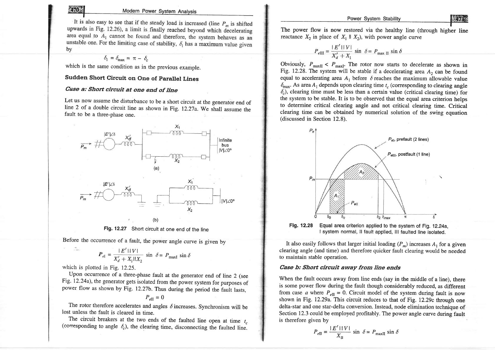
Fig. 12.24
Critical
clearing angle
As the
clearing
of
the faulty line
is delayed, A,
increases and so\oes d,
to
find
A2
=
Ar till 6r
=
6^
as shown
in Fig. 12.24. For
a
clearing
time
(or
angle)
larger
than
this
value, the system
would be unstable
as A, < Ar The maximum
aiiowabie
vaiue of the
clearing
time
and angle for the system to remain stabie
are known
respectively
as critical
clearing
time and angle.
For
this
simple
case
(P,
=
0
during fault), explicit
relationships
for 6,
(critical)
and t"
(critical)
are established
below.
All angles are in radians.
It is
easily
seen
from Fig. 12.24
that
Pm
4nu*=T-
d;
and
P*=
Pr* sin 6o
Now
At=
(P^
--0)
d 6
=
P^
(4,
-
6)
Az=
(P**
sin d-
P^) d6
(
12.59)
(r2.60)
uct
J
h
6^^
J
6,,
and
=
P.u*
(cos
d,
-
cos d-*)
-
P*
(6^o
-
6"i)
ffil
uoo"rn
po*"r
system
Anatvsis
For
the
system
to
be
stable,
A2=
A1,
which
yields
cos
{.
=
!^
(5,^^"
-
Prn*
\
-tniu(
d)
+
cos
4o"*
where
4,
=
critical
clearing
angle
Substituting
Eqs. (1259)
and (12.60)
in
Eq. (12.61),
we get
4r
=
cos-t
[(r,
_
Z6l
sin
do
_
cos
6o]
During
the
period
the
fault
is persisting,
the
swing
equation
is
d,2
d
rf
d,r,
=
1r:
P^:
P,
=
o
Integrating
twice
P*tz
+
$
/cr
=
critical
clearing
time
4,
=
critical
clearing
angle
From
Eq.
(12.6a)
6
=
-,rf-
2H
0",=#
P;2",
160
(r2.61)
(r2.62)
(12.63)
(12.64)
(r2.6s)
where
where
d,
is given
by
the
expression
of
Eq,
(12.62)
An
explicit
relationship
I'rrr
clctenninirtg
r.,
i,
porisiblc
in
this
case
as
tluring
the
faulted
condition
p"
=
o
and
so
trre
,wing
equation
can
be
integrated
in
closed
form.
This
will
not
be
the
case
in
mosi
other
situations.
Sudden
Loss
of
One
of
parallel
Lines
consider
now
a single
machine
tied
to
infinite
bus
through
two
parallel
lines
as
in
Fig.
12.25a.
circuit
model
of
the
sysrem
is given
in
Fig.
r2.25b.
Let
us
study
the
transient
stability
of
the
,yir"rn
when
one
of
the
lines
is
suddenly
switched
off
with
the
system
operating
at
a
steady
road.
Before
switching
off,
power
angle
curve
is given
by
P"r=
lE'llvl
xa
i
xt
llx2
sin
d=
Pm*l
sin
d
Immediately
on
switching
off
line
2, power
angre
curve
is given
by
P"n
=
g:+
sin
d=
pmaxr
sin
d
,\d
-T
rt7
2H(6,,
-
4)
TrfP*
,, /__\ l_Lr__l I
Infinite
,.774
) | I
-l
bus
Pm
tt
\--l
IVVO"
Lrl
IVVO"
(b)
Fi1.12.25
Single
machine
tied
to infinite
bus through
two
par:allel
lines
Both these curves
are
plotted
in
Fig. 12.26,
wherein
P-u*n
(
P_u*r
as
(Yo
* Xr)
>
(Ya
+ Xr
ll X).The system is
operating
initially
with
a steady power
transfer
Pr= P^ at a torque
angle
4
on curve
I.
Immediately
on switching
off line 2,
the
electrical
operating point
shifts to
curve II
(point
b).
Accelerating
energy
corresponding
to area
A,
is
put
into
rotor
followed
by decelerating energy
for
6 >
q.
Assuming
that
an
area A2
corresponding
fo decelerating
energy
(energy
out of
rotor)
can be
found
such
that
At
=
Az, the system will
be
stable
and will
finally
operate
at c
corresponding to a
new, rotor angle
6,
>
60" This
is
so because
a single
line
offers larger
reactance and
larger rotor
angle
is needed
to transfer
the
same
steady
power.
Fig.12.26
Equal
area criterion
applied
to
the
opening
of one
of the
two
lines in
parallel
W
(a)
/
,"
(both
lines
in)
ffiffi-4l
Mod"rn
po*rr.
surt*
nrryr',
4=4o*_T_6,
which
is
the
same
condition
as
in
the previous
example.
Sudden
Short
Circuit
on
One
of
parallel
Lines
Case
a:
Short
circuit
at
one
end
of
line
Let
us
now
assume
the
disturbance
to
be
a
short
circuit
at
the generator
end
of
line
2
of
a double
circuit
line
as
shown
in
Fig.
12.27a.
We
shall
assume
the
fault
to
be
a three-phase
one.
Power
Sy-t--
St"blllry
-
via
the healthy
line
(through
higher
line
reactance
X2 in
place
of Xl
ll Xz)7;
with power
angle
curve
sln
sin
d
obviously, P-o[
(
P-"*r.
The rotor
now
starts to
decelerate
as
shown
in
Fig.
12.28.
The system will be
stable
if a decelerating
area
A,
can be
found
equal to
accelerating
area A,
before
d reaches the
maximum
allowable
value
4o*.At
areaA, depends
upon
clearing time
/.
(corresponding
to clearing
angle
{),
clearing time
must be less
than a certain
value
(critical
clearing
time)
for
the system
to be stable.
It is to
be observed
that the
equal
area
criterion
helps
to determine
critical clearing
angle
and not
critical
clearing
time.
Critical
clearing
time can
be obtained
by numerical
solution
of
the swing
equation
(discussed
in
Section 12.8).
P"y,
prefault
(2
lines)
P6n1,
postfault
(1
line)
?t6
Ffg. 12.28
Equal area
criterion
applied to
the
system
of Fig.
12.24a,
I
system normal, ll fault
applied,
lll faulted
line isolated.
It also easily follows that
larger initial
loading
(P.)
increases
A, for
a
given
clearing
angle
(and
time) and therefore quicker
fault clearing would
be
needed
to
maintain stable
operation.
Case
b: Short circuit away
from line
ends
When the fault
occurs away from line
ends
(say
in
the
middle
of a line),
there
is
some
power
flow
during the fault
though
considerably
reduced,
as
different
from case a where
Pen
=
0.
Circuit model
of the
system
during
fault
is now
shown
in Fig. 12.29a.
This circuit
reduces
to that
of Fig.
12.29c
through
one
delta-star
and one star-delta conversion.
Instead, node
elimination
technique
of
Section 12.3 could
be employed
profitably.
The
power
angle
curve
during
fault
is therefore
given
by
P"t=
| Ellvl
sin
d= Pmaxrr
sin d
'1r'II
X2
,
(b)
F19.12.27
Shoft
circuit
at
one
end
of the
line
Before
the
occurrence
of
a fault,
the
power
angle
curve
is
given
by
'--
p"t
=
,)4,'rlr,,,a,
sin
d=
p_*,
sin
d
'
xi
+
xltx2
which
is
plotted
in
Fig.
12.25.
Upon
occulrence
of
a three-phase
fault
at
the
generator
end
of line
2
(see
Fig.
I2.24a),
the
generator
gets
isolated
from
the
power
system
for
purposes
of
power
flow
as
shown
by
Fig.
12.27b.
Thus
during
the
period
the
fauit
lasts,
The
rotor
therefore
accelerate,
.i;t:;i"s
dincreases.
synchronism
will
be
lost
unless
the
fault
is cleared
in
time.
The
circuit
breakers
at
the
two
ends
of
the
faulted
line
open
at
time
tc
(corresponding
to
angle
4),
the
clearing
time,
disconnecting
the
faulted
line.
ffiil Modern Power svstem Analvsis
+t*F;4-l
'!'vev" '
' - '-
v' v,
-'-" ' '
"
'-',
-'-
I
ls#z#i
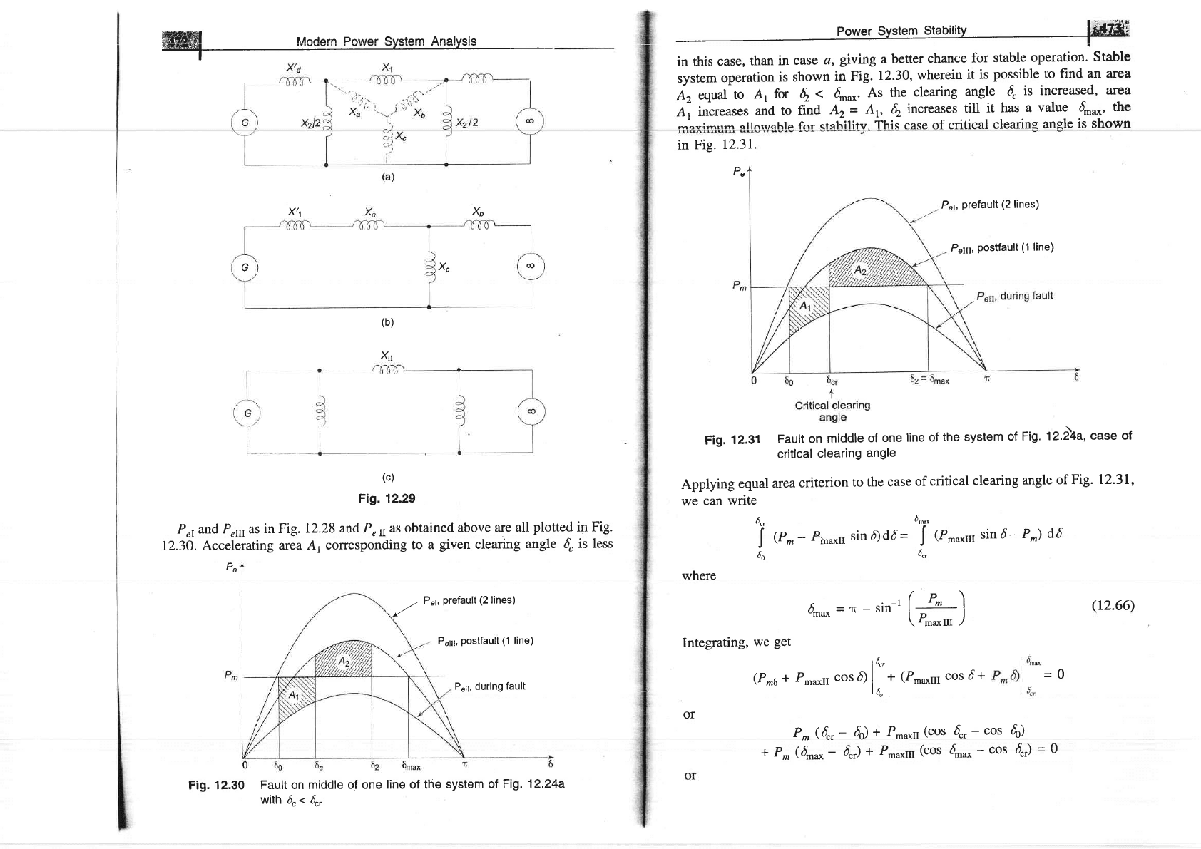
system
operation
is shown
in
Fig.
12.30,
wherein
it is
possible
to
find an area
A,
equal-to
A,
for
q.
<
4nu*.
At
the
clearing
angle
d.
is increased,
area
ai
increat"t
und
to
nna
Az
=
Ar,
4.
increases
till
it has
a
value
4n*'
t6"
-ooi*,,- ollnrvohle fnr stahilitv This case of critical
clearine
angle
is shown
in
Fig.
12.3L
Pe
Fig.
12.31
Fault
on
middle
of
one
line
of
the system
of
Fig.
t2.l4a,
case
of
critical
clearing
angle
Annlvins eoual
area
eriterion
to the
case
of
critical
clearing
angle
of Fig.
12.31'
we can
wnte
4,
dntn'
j
(P^-
4n*u
sinfldd=
J
{r^*r
sind-
P^)
d6
60
6,,
(c)
Fig.
12.29
P"rand
P,u as
in Fig.
12.28
and Per as obtained
above are
all
plotted
in Fig.
I2.3O.
Accelerating
area
A, corresponding
to a
given
clearing
angle
d
is
less
Pe
Fig. 12.30
Fault on middle
of one
line of the
system of
Fig.
12.24a
with d"
<
{,
X6
x,t
(b)
Xr
where
4,,*
=T
-
sin-r
(:t_)
V maxIII
./
Integrating,
we
get
l6*
(P^a
+ Pmaxrr
cos d)
|
*
(P'*,,1
cos
d
+
16o
or
(r2.66)
=Q
P^
(6",
-
6)
*
P.u*u
(cos
'[.
-
cos
do)
I P*
(6**
-
6"r)
*
P-om
(cos
fi*
-
cos
4J
=
0
Pr1,
prefault
(2
lines)
P6111,
postfault
(1
line)
xc
G
@
,.a
P"'Prefault
(2
lines)
P"11;,
postfault (1
line)
P"11, during fault
t
cos
{r
=
:otd",*
4naxtn
-
PmaxII
critical
clearing
angle
can
be
calculated
from
Eq. (12.67)
above.
The
angles
in
:lt::t1|on
are
in
radians.
The
equation
mooiiies
as
below
if
the
angJes
are
ln
oegrees.
cos
{.
-
ft
r.(6
^i*
-
do
)
-
Pmaxrr
cos
do
*
prnu*ru
cos
d,ou*
Pmaxltr
-
Prnaxn
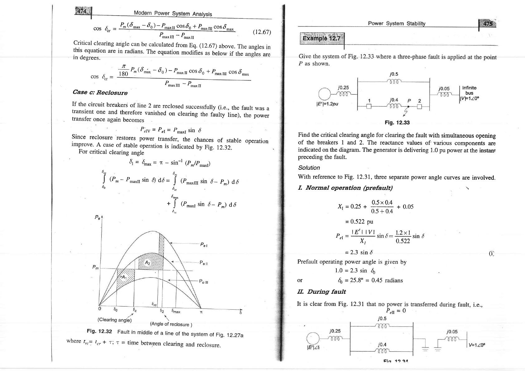
Case
c:
Reclosure
If
the
circuit
breakers
of
line
2
are
reclosed
successfully
(i.e.,
the
fault
was
a
transient
one
and
therefore
vanished
on
clearing
the
faurty
line),
the power
transfer
once
again
becomes
P"N
=
P"r=
p*u*I
sin
d
Since
reclosure
restores
power
transfer,
the
chances
of
stable
operati'n
improve.
A case
of
stable
operation
is
indicated
by
Fig.
12.32.
For
critical
clearing
angle
(Clearing
angle)
\
(Angle
of
reclosure
)
Fig-
12-32
Faurt
in
middre
of
a rine
of
the
system
of
Fig.
12.27a
where
trrj
tr,
+
r;
T
=
time
betw,een
clearing
ancl
reclosure.
(12.67)
4
=
4r*
=
1T
-
sin-l
1p_/p*.*r;
t
ucr
6rc
J
@r,-
Pmaxrr
sin
0
dd
=
J
(p.*m
sin
d_
pm)
d,6
60
6r,
dru,
t
+
J
(P,*r
sin
d_
p^)
d6
6.-
i0.s
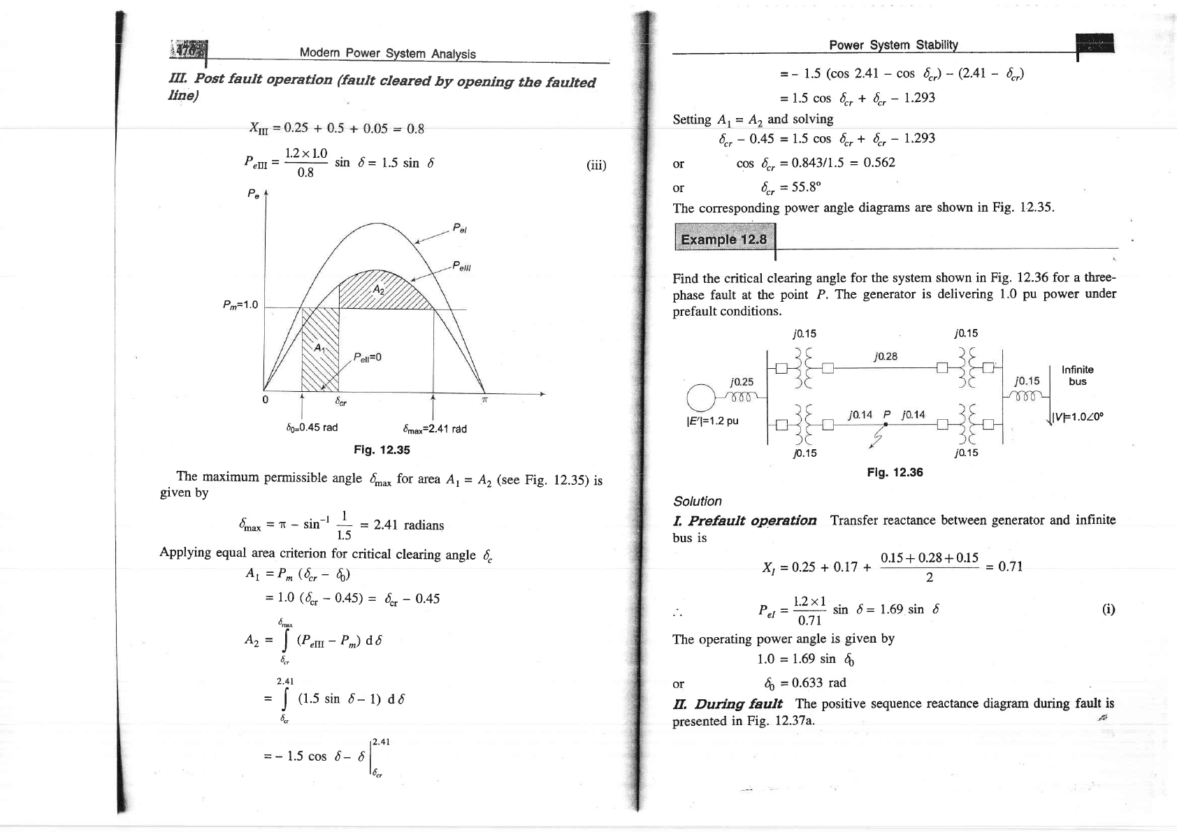
Give the
system of Fig.
P as
shown.
12,33
where a
three-phasc
fault
is applied
at rhe
point
Infinite
bus
vFlloo
Flg.
12.33
Find the critical clearing
angle for
clearing
the
fault with
simultaneous
opening
of the breakers I
and 2. T\e
reactance
values
of'various
components
are
indicated
on
the diagram.
The
generator
is
delivering
1.0
pu power
at
the instanr
preceding
the fault.
Solution
With reference
to Fig.
12.31, three
separate
power
angle
curves
are involved.
f. Normal
operation
(prefault)
Xr=0.2s+ffi+0.05
=
0.522
pu
p,t=rysind:
ffirino
=
2.3
sin d
(il
Prefault operating
power
angle is
given
by
1.0
=
2.3 sin
6
or
6o
=25.8"
=
0.45 radians
IL During fault
It is clear from Fig.
12.31
that no
power
is
ffansferred
during
fault,
i.e.,
,0.:"o
=
o
trin
1n
1A
iffi
Modern
power
System
Anatysis
rrr.
Post
fault
operation
(fault
cleared
by
openingr
the
faulted
Iiae)
U
E
=
-
1.5
(cos
2.41
-
cos
6,)
-
(2.41
-
6")
=
1.5
cos 6",
+
6r,
-
I.293
Setting
A
=
Az and
solving
6r,
-
0.45
=
1.5
cos
6r,
+ 6r,
-
1.293
or
cos
{,.
=
0.84311.5
-
0.562
or
4,
=
55.8"
The
corresponding
power
angle diagrams
are shown in Fig.
12.35.
Find
the critical
clearing
angle
for the system
shown in Fig.
12.36 for a three-
phase
fault
at the
point
P.
The
generator
is delivering
1.0
pu power under
prefault conditions.
n
l.2xl.0
Perrr=
ff
sin
d=
1.5
sin
6
(iii)
Pe
Pn=1
'O
66=0.45
rad
6^rr=2.41
rdd
Fig.
12.35
TTto -ooi*"* -^*:^^:Ll^ ^--l^ C f^- ----- ^ .
rrrw
urour.rLurr
psllluDDlulc
alilBrtr
Omax l()f
afea
Al
=
A2 (Sge
flg.
given
by
4ou*=r-sin-l
I
=
2.4Lradians
1.5
Applying
equal
area
criterion
for
critical
clearing
angle
{
Ar
=
P^
(6",
-
6)
=
1.0
(6",
-
0.45)
=
6c,
-
0.45
dr*
Az=
!{r,n-p^)d,6
6,,
2.41
I
=
|
(1.5
sin
6-
1) dd
J
6.,
r2.41
=-1.5cos
d_
dl
|
6",
i0.1
5
i
0.1s
lnfinite
bus
lvF1.otoo
.10.15
jo.15
Flg. 12.36
Solution
f, Prefault
operation
Transfer
reactance
between
generator
and infinite
bus
is
&
=
0.25
+ 0.17
+
0.15+0.28+0.15
=
0.71
12.35)
is
P-,
=r'Zxl
sin d=
1.69 sin
c'
0.71
(i)
2
6
The
operating
power angle is
given
by
1.0
=
1.69 sin
,fr
or
do
=
0.633
rad
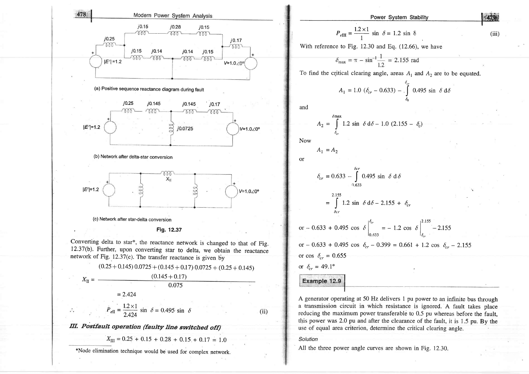
IL
Durtng
fault
The
positive
sequence
reactance diagram during fault
is
presented in Fig.
12.37a.
lF,l=1.2
Pu
j0.25
J
000
L
/
000
L----------r
000
\-
j0.15
j0.14
j0.14
j0.'15
jo.17
+
+
0'
) E1=t.z
V=1.0
(a)
Positive
sequence
reactance
diagram
during
fault
j0.25
j0.145
j0.145
',
j0.17
lE'l=1.2
V=1.OlOo
(b)
Network
after
ddlta-star
conversion
l9l=1'z
V=1.0100
(c)
Network
after
star-delta
conversion
.
Ftg.
12.32
Converting
delta
to
star*,
the
reactance
network
is changed
to
that
of
Fig.
12.37(b).
Further,
upon
converting
star
to
delta,
we
obtain
the
reactance
network
of
Fig.
.r2.37(c).
The
transfer
reactance
is
given
6y
(0.2s
+
0.145)
0.072s
+
(0.145
+
0.17)
0.0725
+
(0.25
+
0.145)
Xu=
(0.14s
+
0.17)
0.075
_
2.424
p
- =
lal!
sin
d
=
0.495
sin
6
r
eI
-
i.+Z+
uur
v
-
v.a/,
Postfault
operation
(faulty
line
switched
off)
Xrl
=0.25
+
0.15
+
0.28
+
0.15 +
0.17
=
1.0
*Node
elirnination
technique
would
be'used
for complex
network.
fir.
(ii)
Power
System
Stabilit-v
Mi#ffi
r*
Perrr=U!
sin
d
=
r'2 sin
6
'l
With
reference to Fig. 12.30
and Eq.
(12.66),
we have
(iii)
To
find the cqitical
clearing angle, areas
A1
and A, arc
to
be equated.
6",
At
=
l.o
(6,,-
0.633)
-
,
J
o.+e5 sin
d dd
60
and
dmax
f
Az
=
|
1.2 sin
ddd- 1.0
(2.155
-
4)
-J
6
-cr
Now
At
=Az
or
6r,
=
0.633
---
o
2.155
=
[
t.Z
rin 6 d6
-
2.t55 +
6,,
J'
6cr
or
-
0.633 +
0.495 cos olo'
=
-
1.2 cos
ol"tt
-2.155
lo.orr
la.,
or
-
0.633
+
0.495 cos 6,,
-
0.399
=
0.661
+ 1.2 cos
6",
-
2.155
or cos
6r,
=
0.655
U 6r,
=
49.I"
A
generator
operating at 50 Hz delivers
1
pu power
to
an
infinite
bus through
a transmission
circuit in which
resistance
is ignored.
A fault
takes place
reducing the maximum
power
transferable
to
0.5
pu
whereas
before the
fault,
this
power
was 2.0
pu
and
after
the
clearance
of the fault,
it
is 1.5 pu.
By the
use
of equal
area
criterion, determine
the critical
clearing
angle.
Solution
All
the three
power
angle curves are
shown
in Fig. 12.30.
J
.63
0.495
sin
d
dd
J
,'ffi|
Mod"rn Po*..
sEl!"-n An"lytit
Ilere
P-"*r
=2.0
pu,
Pmaxl
=
0.5
pu
and Pmaxrrr
=
1.5
pu
Initial loading
P^
=
1.0
pu
Applying
Eq.
cos
{,
-
(p\
6r,ro= zr sin
I
tffiJ
E7-sinl
1
:2.4!rad
1.5
(r2.67)
1.0(2.41
-
0.523)
-
0.5
cos 0.523
+
1.5 cos 2.41
=
o
???
1.5
--
0.5
6r,
=
70'3"
T2.9
NUMERICAT
SOTUTION
OF SWING
EOUATION
In most
practical
systems,
after machine
lumping
has
been
done, there
are still
more than
two machines
to be considered
from
the
point
of view of
system
stability.
Therefore, there
is no choice
but to solve
thp
swing
equation of
each
machine
by a numerical
technique on the
digital computer.
Even in
the case
of
a single
machine
tied to
infinite bus bar, the
critical
clearing
time cannot
be
obtained
from
equal area
criterion and
we have
to make
this
calculation
! . .rr-- rr------ -l- ----:- - -----Ll^,
zFL^-^
| -^-Ll^+i^^+^l *^+L^l-
numerlca[y
mrougn swulg
equauulr.
t rttrIc aIU ssvtrIilr
JuPurDtruilL('(l
lllELlluLlD
now
available
for the solution
of
the swing equation
including
the
powerful
Runge-Kutta
method.
He.re
we shall treat the
point-by-point method of
solution
which
is
a conventional,
approximate method
like
all numerical
methods
but
a
well tried
and
proven
one.
We
shall
illustrate the
point-by-point method for
one
machine
tied
to infinite
bus bar.
The
procedure
is, however,
general
and can
be
applied-to
every machine
of a multimachine
system.
Consider
the swing
equation
d26
1 --
;T
=
;e*-P^*sind):
PolM;
(*
-
9H
orin
pu
system
M
=
+)
\
7t
iTf)
The
solution
c(r)
is obtained
at
discrete
intervals
of time
with interval
spread
of
At uniform
throughout.
Accelerating
power
and change
in speed
which
are
continuous
functions
of time are
discretrzed
as below:
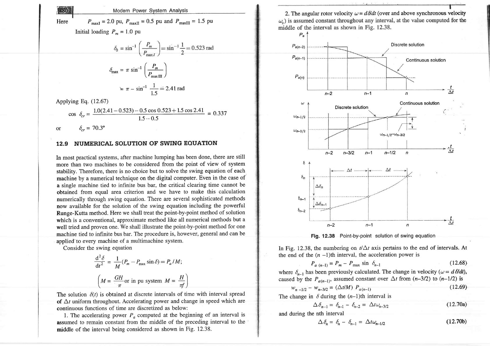
1.
The accelerating
power
Po computed
at the
beginning
of an interval
is
assumed
to remain constant
from
the middle of
the
preceding
interval
to
the
middle
of
the interval being
considered
as shown
in Fig.
t2.38.
r>2
n-1
Discrete
solution
n
Continuous solution
U
un-|/2
u13/2
un-I/T-+tsn4l2
n-2
p3l2
n-'l r>112
n
6n-z
n-2
n-1
n
Fig. 12.38
Point-by-point
solution
of swing equation
In Fig.
L2.38,
the numbering
on tl\t
axis
pertains to the
end of
intervals. At
the end
of the
(n
-l)th
interval,
the
acceleration
power
is
Pa
(n_r)--
Pm- P-* sh
4-r
Q2.68)
where
d_1
has
been
previously
calculated.
The change
in velocit!
(a=
d6ldt),
caused by
the Pa@-r),
assumed constant
over
At from
(n-312)
to
(n-ll2)
is
t
Af
-t
Af
$n-i
J-
Af
wn-'2-
wn-3t2=
(Lt/M)
Pa@-r)
The change
in
d during
the
(n-l)th
interval
is
L6r-t=
6r-1
-
6n-2=
A'tun4'2
and during
the
nth
interval
L6r-
6n- 6n-t=
/\tun-112
(12.6e)
(12.70a)
(12.70b)
2.The
angular
rotor
velocity
u= d6ldt
(over
and above synchronous
velocity
t
,ir
Yirtvt
r
t Ar
lr.rl br)
Subtracting Eq.
(12.70a\
from
Eq.
(12.70b)
and using Eq.
(12.69),
we
get
L'6,= A6,-t +
Using this,
we can
write
(12.7r)
6n
=
6n-t
+ L,6n
G2.72)
The
process
of computation
is now
repeated to obtain
Pa61, L6r*tand
d*t.
The
time solution in discrete form
is thus
carried out over the
desired
length of time,
normally 0.5 s. Continuous
form
of solution is obtained
by drawing
a
;mooth
curve
through discrete
values as shown
in Fig. 12.38. Greater
accuracy of
solution can be achi.eved by
reducing the
time duration
of intervals.
The occurrence or removal
of
a fault or initiation
of any switching
event
causes
a
discontinuity
in accelerating
power
Po.lf such
a discontinuity
occurs
at the beginning of an
interval, then the average
of the
values of
Po before
and
after the discontinuity
must be
used.
Thus, in computing
the increment
of angle
occurring
durirrg the
first interval
after
a
fault is applied
at t
=
0,
Eq.
(I2.7I)
becomes
7,,6,
=
(Ar)t
*Pao+
,M2
where Pos*
is the accelerating
power
immediately
after occurrence
of
fault.
Immediately before
the fault the system is in steady
state, so
that Poo-
=
0 and
ds is a known
value. If the fault
is cleared at the beginning
of
the nth interval,
in calculation for
this interval one should
use for Pa@-r)
the value
llP"6-r>-
+ Po6_9*), where
Pa@_r)- is the accelerating
power
immediately
before
clearing
and Po6_r)+ is that
immediately
after clearing
the
fault. If the discontinuity
occurs
at ihe miciciie of an
intervai, no speciai
proceciure is neecled. The
increment
of angle
during such an
interval is calculated, as
usual, from the
value of Po at the beginning
of
the interval.
The
procedure
of calculating
solution of swing
equation is
illustrated
in the
following example.
A 20
MVA,
50
Hz
generator
delivers 18 MW over a
double circuit
line to
an
infinite bus. The
generator
has
kinetic energy of 2.52 MJA4VA
at rated
speed.
The
generator
transient reactance
is X/o
=
0.35
pu.
Each transmission
circuit
has
R
=
0
and a reactance of 0.2
pu
on a 20 MVA bgq-e. lE/l
=
1.1
pu
and
infinite bus voltage V
=
7.0
10".
A
three-phase
short circuit occurs
at the
mid
point
of one of the
transmission lines. Plot swing
curves with
fault cleared by
simrrltaneous opening
of breakers
at both ends of the line at2.5
cycles and 6.25
cycles after the occuffence
of fault. Also
plot
the
swing curve over
the
period
of
0.5 s if the fault is sustained.
(A
r)2
D
M
r
a(.n-I)
power
System Stabilitv
[i{8il;r
Q^t,,1;^^ E ^f^-^ ^-*1,, +L^ ^+^- L.. ^+^- -^rl.^l - ^ -t ^- - -r ---r-a-
\rvtu.,v,t nsluls
ws Lall aPPt.y
ultt
stEP-Uy-slttP
lIIculUU,
Wtr
lltrC(l t()
Calculate
the inertia
constant M and
the
power
angle equations
under prefault
and
postfault
conditions.
Base MVA
=
20
IneRia
coflstant, Mepu\
=
180
/
1.0
x
L52
180
x
50
I
I Prefault
=
2.8
x
10+ s2le\ect
degree
&=0.35+
0'2
=0.45
'2
Pd= Pr.*r
sin d
!,.lxt
.
r
=
-'.-;;sin
d
=
2.M sin 5
(i)
Prefault
power
transf'er
=
+
=
0.9
pu
20
Initial
power
angle is
given
by
2.44sin4=0.9
or
6o= 21.64"
\
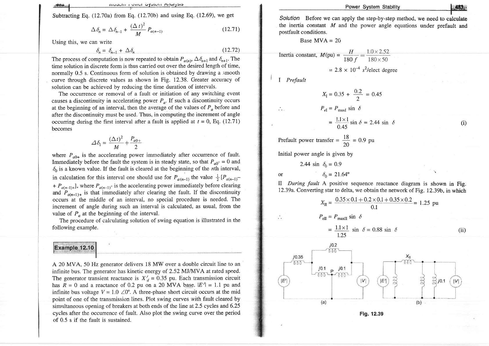
II During
fault
A
positive
sequence reactance
diagram
is shown
in Fig.
12.39a. Converting star to delta,
we obtain the network
of
Fig.
12.39b,
in
which
,,
0.35
x
0.i
+
A.2x0.i
+
0.35x0.2
1 A-
trtr
=
-
0l
-=
I..Z)
pu
P.u
=
Pmaxtt
sin
d
-
1'1x 1
r;n
d
=
0.88 sin
6
1.25
(ii)
Fig. 12.39