Kothari D.P., Nagrath I.J. Modern Power Systems Analysis
Подождите немного. Документ загружается.

I
I
where
P^^,
=
lE''
I lE''
|
'
'-x'
simplified
power
angle
equation
Yl aZt
+=
-
P^
Pn'u*
sin dpu
7rI dt-
where
X
=
transfer
reactance between
nodes
(i.e.,
between
E{
'Ihe
graphical
plot
of
power
angle
equation
(Eq.(12.29))
is
Fig.
12.6.
p"l
I
D
I
max
(Ps6+APe).-....t-----*
Peo
-
Generator
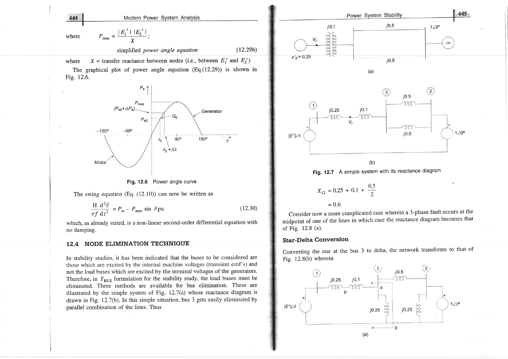
Fig. 12.6 Power
angle
curve
The swing
equation
(Eq. (12.10))
can now
be written
as
j0.5
i0.5
lE'lt6
1
lo"
(b)
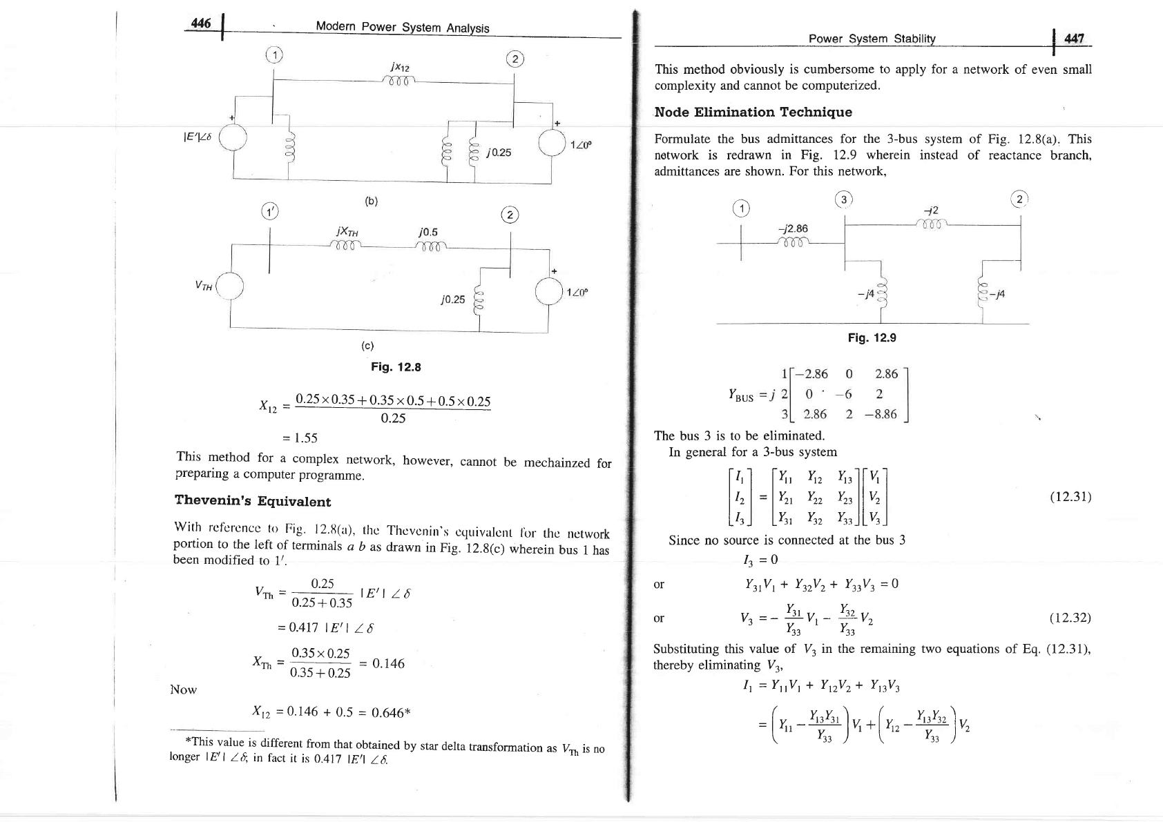
F|g.12.7Asimp|esystemwithitsreactancediagram
0.5
Xrz
=0'25
+ 0'1
+
-
=
0.6
Consider
now
a
more
complicated
case
wherein
a 3-phase
fault
occurs
at
the
midpoint
of
one
of
the
lines
in
which
case
the
reactance
diagram
becomes
that
of
Fig.
12.8
(a).
Star-Delta
Conversion
Converting
the
star
at
the
bus
3
to
delta,
the
network
transforms
to
that of
Fig.
12.8(b)
wherein
(,
j0.25
at(
-U
(r2.29b)
and
Ei)
shown in
(12.30)
which, as
already
stated, is
a non-linear
second-order
differential
equation
with
no damping.
T2.4
NODE
ELIMINATION
TECHNIOUE
In stability
studies,
it has been
indicated
that the
buses
to be considered
are
those
which
are
excited by
the internal
machine
voltages
(transient
emf's)
and
not the
load
buses
which
are
excited by the
terminal
voltages
of the
generators.
Therefore,
in
Y"u,
formulation
for the
stability study,
the load buses
must
be
eliminated.
Three
methods
are available
for bus elimination.
These
are
illustrated
by the
simple system
of
Fig. 12.7(a)
whose
reactance
diagram
is
drawn in
Fig. I2.7(b).In
this simple situation,
bus 3
gets
easily
eliminated
by
parallel combination
of the lines.
Thus
o
(a)
lE/lt6
1ttr
446
L
Modern
power
System
Anatysis
lE/lt6
CD
(c)
Fig.
12.8
v
_
0.25
x
0.35
+
0.35 x
0.5
+
0.5
x0.25
=
1.55
This
method
for
a
complex
network,
however,
cannot
be
mechainzed
for
preparing
a
computer
programme.
Thevenin's
Equivalent
With
ref'crcncc
lo
Fig.
l2.ti(a),
tho
Thcvcnirr's
ccluivalcnt
lbr
thc
network
portion
to
the
left
of
terminals
a
b
as
drawn
in
Fig.
12.8(c)
wherein
bus
t has
been
modified
to
1/.
lut
Power
System Stability
,
-
_
This method obviously
is cumbersome
to
apply for a network
of even small
complexity and cannot be computenzed.
Node Elimination Technique
Formulate
the
bus admittances for
the
3-bus system of
network is redrawn
in Fig.
12.9
wherein
instead of
admittances are shown. For this network.
Fig. 12.8(a). This
reactance
branch.
(r
ra
(r2.31)
(r2.32)
of Eq.
(12.31),
@
o
ruus
The bus 3
is to be
eliminated.
In
general
for a 3-bus system
f''I fr'
Y" t"lIu'I
lh |
=
lY^
Y,
vu
llv, I
Llrl Lv,,
Yn rrrJL%l
Since no source
is connected at the
bus
3
It
=o
or
YrrVr+
YrrVr+ YrrVr=O
or
vz=-?rr-
?r,
Yrt Y.,
Substituting
this value of V3
in the remaining two equations
thereby eliminating
Vy
It
=Y,Vt
* YrzVz+ YttVt
=(",
-
Y,rYr,
)
u
+(
y,"
-!+)v"
-(.^tt
Yr,
'['t'
Yr,
)''
, r
0.25
vrh
=
025+0-,5
lEtl
l5
=
0.417
|
Et
I
16
0.35x0.25
xrh
=
035+025
-
o'146
Xt2
=0.146
+
0.5
=
0.646*
*This
value
is different
from
that
obtained
by
star
delta
transformation
as
longer
lEtl
I
{
in
fact
it
is
0.417
lEtl
16.
Itlow
Fig.
12.9
V*
is
no
In compact
form
Ynus
(reduced)
=lt,i,'
l,l,'1
lY'r,
Y'r,
)
Y'tl=Y"-ry
'33
Y'12
=
Y'21= Ytz
-
vt,=yrr-YrtYt
t
22
-
'zz
yT
In
general, in eliminating
node n
Yo^(old)Y,,(old)
Yo,
(new)
=
Yry
(old)
Applying
Eq.
(
12.34)
to the example
in hand
l-t.gzt
Ysu5
(reduced)
=
;
1
0.646
L
It then
follows that
X,t=:-
=1.548(
=
1.55)
o.646
In
the
systenr
shown
in Fig.
12,10, a
three-phase
static capacitive reactor of
reactance
1
pu per
phase
is connected through
a switch
at motor
bus bar.
Calculate
the limit
of steady
state
power with
and
without reactor
switch closed.
Recalculate
the
power
limit
with capacitive
reactor replaced
by
an
inductive
reactor
of the same
value.
to
be
1.0
pu.
Solution
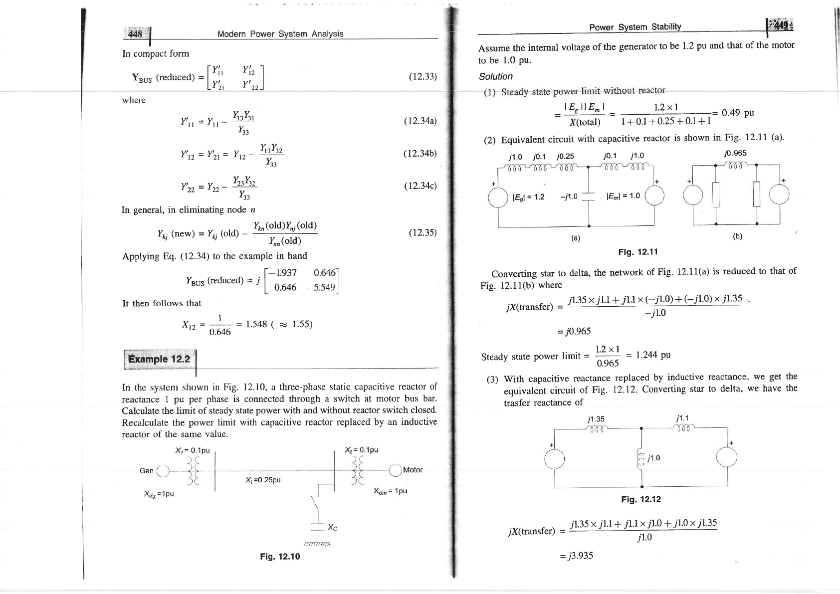
lErllE^l
I.ZxI
=ffi=m=o'49Pu
(2)
Equivalent
circuit
with
capacitive
reactor
is shown
in Fig.
12.71
(a).
j1.o
jo.l
i0.25
io.1
i1.o
p'e65
lEnl
=
1.2
-i1.0
=
lEml
=
1.0
(a)
(b)
Flg.
12.11
Converting
star
to
delta,
the
network
of
Fig.
12.11(a)
is
reduced
to
that
of
Fig.
12.11(b)
where
7X(transfer)-/1.35X/1.1+/1.1X(_J1.0)+(-/1.0)XJ1.35..
-j1.0
= j0.965
.
1.2x1
Steady
state
power
limit
=
ffi
=
1-244
pu
(3)
With
capacitive
reactance
replaced
by
inductive
reactance,
we get
equivalent
circuit
of
Fig.
12.12.
Converting
ster
to
delta,
we
have
trasfer
reactance
of
i1.35
i1.1
Fig.12.12
_
j1.35
x.r1.l
+
"11.1x
ll.0
+
11.0
x.t1.35
i
1.0
-
j3.e35
YrtYt,
Ytt
(12.33)
Q23aa)
(r2.34b)
(r2.34c)
(r2.3s)
the
the
Fig. 12.10
7X(transfer)
-!5o'
l
""attt
t"-t,
Steady
state power
timit
-':'!]
=
0.304
pu
3.935
Example
12.3
The generator
of Fig.
12.7(a)
is
delivering
1.0
pu
power
to
the
infinite
bus
(lVl
=
1'0 pu),
with
the generator
terminal
voltage
of
v,r
=
1.0 pu.
calculate
the
generator
emf
behind
transient
reactance.
Find
the
maximu-
io*".
that
can
be
transferred
under
the
following
conditions:
(a)
System
healthy
(b)
One
line
shorted
(3_phase)
in
rhe
middle
(c)
One
line
open.
.
Plot
all
the
three
power
angle
curves.
Solution
L,et
Vt
=
lV,l
la
=
|
la
From
power
angle
equation
tvt
llv
I
_---
stn
o=p"
X
(
t"t
)
[025+oJJsrn
<t
=
I
or
rr
=
20.5"
Current
into
infinite
bus.
Power System Stability
hiffi
As already
calculated
in
this
section,
Xn
=
l'55
=
!".!;!!
=
0.6e4
pu
or
P,
=
0.694
sin d
(ii)
(c)
One line open:
It easily follows
from Fig.
12.7(b) that
Xrz
=0.25
+
0.1
+ 0.5
=
0.85
P*.*=tit^o]t
=r.265
0.85
or
P"
=
I.265 sin 6
(iii)
The
plot
of the
three
power
angle
curves
(Eqs. (i),
(ii)
and
(iii))
is
drawn
in
Fig.
12.13.
Under
healthy
condition, the system
is operated with P,,
=
P,
=
1.0
pu
and 6o= 33.9",
i.e., at the
point
P on the
power
angle
curve 1.79 sin
d As
one
line is
shorted
in the middle,
Po, remains fixed
at 1.0
pu
(governing
system
act instantaneously)
and is further
assumed to remain fixed throughout
the
transient
(governing
action
is slow),
while the
operating
point
instantly shifts
to
Q
on thc
curvc 0.694
sin dat d= 33.9".
Noticc thut bccuusc
of
machine inertiu,
the rotor
angle can
not change
suddenly.
1.79
1.265
Pn=1
'O
0.694
0
0.694
sin 6
33.90
I
900
A
Fig. 12.13 Power angle curue,s-
I2.5 SIMPLE
SYSTEMS
Machine Connected
to Infinite
Bus
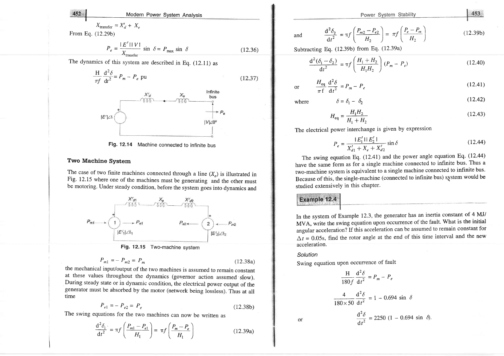
Figure 12.14
is
the circuit model
of a single machine connected to infinite
bus
through
a line of
reacthnce
Xr.In this simple
case
lV,lla-lVll0"
jx
|
120.5-
I
l0
i0.3s
=l+j0.18=1.016
110.3"
Voltage
behind
transient
reactance,
Et
=tltr
+
.j0.6
x
(l
+
70.1g)
=
0.892
+
j0.6
-
1.075
133.9"
(a)
System
healrhy
p^u*
=
lv
)-l
Et
|
-
1x
1.075
-
.,
F,.\
,-,
x,,
-
c,5
=
t't9
PU
P,
=
I'79
sin
d
(b)
One
line
shorred
in
the
middle:
I_
(i)
I
Xtransf.er
=X'a*
X,
From
Eq.
(12.29b)
,,
='4U
sin
d=
p.u*
sin
d
Xt
urrrf..
The
dynamics
of this
sysrem
are
describecl
in
Eq.
(12.11)
as
-#ft=
P^-
P"
Pu
Prl=-Prz=
P"
The
swing
equations
for
the
two
machines
can
now
be
written
as
tL
__r(P^r_
P"r)
_
_"
(p.-+\
dtz
-"'i
ff,
):ut
t
rr,
l
(r2.36)
lE/lt6
Fi1.12.14
Machine
connected
to
infinite
bus
Two
Machine
System
The
case
of two
finite
machines
connected
through
a line
(X")
is
illustrated
in
Fig.
12.15
where
one
of
the
machines
must
be
generating
und
th"
other
must
be
motoring.
Under
steady
condition,
before
the
system goes
into
dynamics
and
Fig.
12.15
Two-machine
svstem
P*t=-P*z=P.
(12.38a)
the
mechanical
input/output
of
the
two
machines
is assumed
to remain
constant
at
these
values
throughout
the
dynamics (governor
action
assumed
slow).
During
steady
state
or
in
dynamic
condition,
the
electrical
power
output
of the
generator
must
be absorbed
by the
motor
(network
being
lossless).
Thus
at
all
time
(12.38b)
(12.39a)
t-
Power
System
Stability
I
lt5'
d26"
.(P-r-P"r\
(r--n-)
and
it
="f
l2?:)=
"tlH')
Subtracting
Eq.
(12.39b) from
Eq.
(12.39a)
d2@,;6)
=^r(':jr!,]
,.-
-
P,)
dtz
.J
\
HrH,
)
H"q
d26
or
-*
.,
=Pn-
P,
7r
I
(lt-
where
6=4-
6.
rr
-
HtH,
"eq
Hl
+
Hz
The
electrical
power
interchange
is
given
by
expression
p"
=
,E!4!-
,in6
'
X'0,
+
x,
+
xd2
(r2.39b)
(r2.40)
(r2.4r)
(r2.42)
(r2.43)
(12.44)
The
swing
equation
Eq.
(12.41)
and
the
power
angle
equation
F;q-
(12.aa)
have
the
same
form
as
for
a single
machine
connected
to
infinite
bus.
Thus a
two-machine
system
is
equivalent
to
a single
machine
connected
to
infinite
bus.
Because
of
this,
the
single-machine
(connected to
intinite
bus)
qYstem
would
be
studied
extensively
in
this
chapter.
In
the
system
of
Example
12.3,
the
generator
has
an
inertia
constant
of
4
MJ/
MVA,
write
the
swing
equation
upon
occurrence
of
the
fault.
What is
the
initial
angular
acceleration?
If
this
acceleration
can
be
assumed
to remain
constant
for
Lt
=
0.05s,
find
the
rotor
angle
at the
end
of
this
time
interval
and
the new
acceleration.
Solution
Swing
equation
upon
occurrence
of
fault
H
d'6
_o D
1g0f dv
-
r
m-
'e
4
d,26
,
*"t#=l-0'694
sin
6
t4
=
z2so
(1
-
0.6e4
sin
d;.
dt"
,.4#jirf
vooern
power
sysrem
Anatysis
I
Initial
rotor
angle
do
=
33.9"
(calculated
in
Example
12.3)
a2 sl
;l
=
2250
(l
-
0.694
sin
33.9")
dt'
l,
-
n+
#l *
=
0;
rotor
speed
cannot
change
suddenly
Cll
lr:
o+
A,
(in
A,t
=
0.05s)
=
x
1379
x
(0.05)2
7"
+
4,6
=
33.9
+
1.7"
=
35.6"
I
2
t.
6
6t=
a26l
. , |
=
2250
(l
-
0.694
sin
35.6")
drl
lr =
0.05s
-
l34I
elect
deg/s2
Observe
that
as
the
rotor
angle
increases,
the
electrical
power
output
of the
generator
increases
and
so
the
acceleration
of the
rotor
reduces.
12.6
STEADY
STATE
STABILITY
The
steady
state
stability
limit
of
a
particular
circuit
of
a
power
system
is
definecl
as
the
maximutn
power
that
can
be
transmitted
tri fhe receivino
en;
without
loss
of synchronism.
v'r6
vrru
Consider
the
sirnple
system
of
Fig.
12.14
whose
clynamics
is
describect
by
equations
M*
=
P^
P"
MW;
Eq.
(12.8)
dl
MH
=
7
ln
Pu
sYstem
and
p,
=
!4)!
)
,in
6'=
p^u*sin
d
x,t
For
determination
of
steady
state
stability,
the
direct
axis
reactance
(X.r)
ant,
voltage
behind
X4
are
used
in
the
above
equahons.
The
plot
of Eq.
(12.46)
is given
in
Fig.
12.6.
Let
the
system
be
operaring
with
steady
power
transfer
of
P^
=
P^with
torque
angle
d
as
indicated
in the
figure.
Assume
a
small
increment
AP
in
the
electric
power
with
the
input
from
the prime
mover
remaining
fixed
at
p*(governor
r.rforrr"
is
slow
compared
to
(12.4s)
(12.46'
L ltc..:'
]i;E!!";1&t
ffi
Linearizing
about
the
operating
point
Qo
(P"0,
4)
*"
can
write
LP,=(*).
o,
The
excursions
of
A d
are
then
described
by
no
9i+'
-
P^
-
(P,o
+ aP,')
=
-
L,P,
d,r
M
d'+'
*
dr
(r2.47)
where
The
system
equation
Pd
dt
stability
to
small
changes
is determined
from
the characteristic
Mp,
+[#],
=o
whosc
two
roots
are
f /t\tr ,.1
(\
f{
P=+l-\u1t0o)o
l-
LMI
As
long
as
(0P/0
0o
it
positive, the
roots
are
purely imaginary
and conjugate
and
the
system
behaviour
is oscillatory
about
do.
Line resistance
and
damper
windings
of
machine,
which
have been
ignored
in the
above
modelling,
cause
the
system
oscillations
to decay.
The system
is therefore
stable for a
small
increment
in
power
so long
as
(a
P,/aa|
> o
(12.48)
When
(0
P/AD,
is
negative,
the
roots
are real,
one
positive and the
other
negative
but
of
equal
magnitude.
The
torque
angle therefore
increases
without
bound
upon
occurrcncc
ol
a small
powcr incretrtent
(disturbancc)
and
the
synchronism
is soon
lost.
The
system
is
therefore
unstable
for
@
Pe/aDo
< 0
@p/A[ois
known
as synchronizing
cofficienr.
This is
also called
stffiess
(electrical) of
synchronous
machine.
Assuming
lEl
and
lVl
to
remain
constant,
the
system
is unstable,
if
lEllvl
cos
d^<o
X
po*e,
systm
st"uititv
b{dffi
r-
or
4>90"
The
maximum
power
that
can
be
transmitted
without
loss
of
stabili
(12.4e)
and
is
given
by
(
r
2.s0)
(12.sr)
lEnvl
If the
system
is
operating
below
the
limit
of
steady
stability
condition
(Eq.
12'48),
it
may
continue
to
oscillate
for
a
long
time
if
the
iamping
is
low.
Persistent
oscillations
are
a
threat
to
system
security.
The
study
oi
system
damping
is
rhe
study
of
dynamical
stability.
The
above
procedure
is
also
applicable
for
complex
systems
wherein
governor
action
and
excitation
control
are
also
accounted
for.
The
describing
differential
equation
is
linearizecl
about
the
opcrating
point.
Conclitiep
fbr
steady
state
stability
is
then
determined
from
the
corresponding
characteristic
equation
(which
now
is
of
order
higher
than
two)
It was
assumed
in
the
above
account
that
the
internal
rnachinc
voltage
lEl
remains
constant
(i.e.,
excitation
is
held
constant).
The
result
is
that
as
loading
increases,
the
terminal
voltage
lv,l
dips
heavily
which
cannot
be
toleratcd
in
practice.
Thereforc,
we
must
consicler
the
steady
state
stability
limit
by
assuming
that
excitation
is
adjusted
for
every
load
increase
to
keep
lv,l
constanr.
This
is
how
the
system
will
be
operaied
practically.
It
may
be
understocd
that
we
are
still
not
considering
the
effect
of
automatic
excitation
control.
steady
state
stability
limit
with
lv,l
anrt
lvl
constant
is
consiclered
in
Example
12.6.
A synchronous
generator
of
reactance
1.20
pu
is
connected
to
an
infinite
bus
bar
(l
Vl
=
1.0 pr)
through
transformers
and
a
line
of total
reactance
of
0.60 pu.
The generator
no
load
voltage
is
I .20 pu
and
its
inertia
constant
is
H
=
4
MW-
silvIVA.
The
resistance
and
machine
damping
may
be
assumed
negligible.
The
system
frequency
is
50
Hz.
Calculate
the frequency
of
natural
oscillations
if
the
generator
is
loaded
to
(1)
50Vo
and
(ii)
80Vo
of its
maximum
power
limit.
Solution
(i)
For
50Vo
loading
I
ae1
L2xr
l--e |
_
____
cos 30"
L
06
Jro"
1.8
=
0.577
MW
(pu)/elect
rad
H4
M(pu)
=
o*ro
=
trx5o
s?/crcct
ratr
From
characteristic
equation
-+i(WiY")u
==
i4.76
P^u*
P=tr[(*),,"1*)'
FrequencY
of
oscillations
=
(ii)
For
807o
loading
4.76
railsec
4'76
-
0.758
Hz
2r
sin
do
=+
=0.8or
6=53.1"
P-u*
rqa)
-
r'Zxr
cos
53.1"
\
05
)rr,
1.8
=
0'4
MW
(Pu)/elect rad
p
=!,
(q+k)*
=*
i3s6
Frequency
of
oscillations
=
3.96
radlsec
P
sm
do
-it
'
max
?q6
')*
Find
the
steady
state
power limit
of
a system
consisting
of
a
generator
equivalent
reactance
0.50
pu
connected
to an
infinite
bus
through
a
series
rcactance
gf
1.0
pu.
The
terminal
voltage of
the
generator
is held
at
1.20
pu
and
the
voltage
of
the
infinite
bus
is 1.0
pu.
Solution
The
system
is shown
in
Fig.
12.16.
Let
the
voltage
of
the infinite
bus be
taken
as
reference.
=0.5or
4=30o
Then
Now
V=7.0
/-ff,
I_
lE4t6
E
=
Vt
+
jXdI
=
1.2
l0
+
j0.5
or
Now
0
=
73.87"
Vt
=
1.2
/.73.87"
=
0.332
r
_
0.332+.ir.rs2_r
=
t.t52
+
j0.669
E
-0.332
+
jr.r52
+
70.5
(1.152
+
j0.668)
-
0.002
+
j1.728
=
1.728
I90.
Steady
state
power
limit
is
given
by
p^u
-lEllVl
1.728xL
*=
V;-+V
=
--i5
=
l'152
Pu
If
instead,
the generator
emf
is
held
fixed
at
a
value
of
r.2pu,
the
steady
state
power
limit
would
be
P*"*
=
i#
=
o'8
Pu
It
is
observed
that
regulating
the
generator
emf
to
hold
the
terminal
generator
','oltage
at
r.2
pu
raises
thepowerli.it
frorn
0.g pr'ro
r.r52pu;
this
is
how
the
voltage
regulating
loop
helps
in power
system
stab'ity.
Xa=
O'5
I
Vt=
1.219
m
Analysis
Vt
=
!.2
l0
1.210-7.0
jI
V
=
1.0100
Flg.
12.16
.E
=
l.g
l0
_
0.5
=
(t.g
cos
e_
0.5)
+
71.g
sin
0
Steady
state porver
rimit
is
reached
when
E
has
an
angle
of
6=
90o,
i.e.,
its
real
part
is
zero.
Thus,
1.8cos
0-0.5=0
r.2
lg
-
1.0
r
I
L
I
J
Power
Srrstem Stahilitu
EsE
A knowledge of steady
state
stability
limit
is important for various reasons.
A
system can be
operated above its transient stability limit
but not above
its
steady-tatelimit.
Nowrwith increased fault el,earing
speedsjt is
possible
to
make the transient
limit closely approach the steady
state
limit.
As is clear
from Eq.
(12.51),
the methods of improving
steady state stability
limit
of a system
are to reduce X and increase either
or both
lEl
and I Vl.
If the
transmission
lines are of sufficiently high reactance,
the stability limit
can be
raised by using
two
parallel
lines
which
incidently also
increases the reliability
of the system. Series
capacitors are sometimes employed
in lines to
get
better
voltage
regulation and to raise the stability limit by
decreasing the line
reactance. Higher excitation
voltages and
quick
excitation
system are
also
employed
to improve the stability limit.
I2.7 TRANSIENT
STABITITY
It has been
shown in Sec. L2.4 that the dynamics of
a single synchrono,rs
machine connected
to infinite bus bars is
governed
by the
nonlinear
differential
equation
+
jt.152
,,
d'6
M
iF
=P^-
P"
where
P,
=
P-*
sin d
-_
d26
or
M
--+
-
P*- P** sind
ot-
(r2.s2)
As said earlier,
this equation is known as the
swing equation.
No closed
form
solution exists for swing
equation except
for the simple
case P-
=
0
(not
a
practical
case) which
involves elliptical
integrals. For
small
disturbance
(say,
gradual
loading), the equation
can
be
linearized
(see
Sec. 12.6) leading
to the
concept
of steady state stability where a unique
criterion of
stability
(APrlAd>0)
could be established. No
generalized
criteria
are available*
for
determining
system stability
with
large disturbances
(called
transient stability).
The
practical approach to the transient stability
problem
is
therefore to list
all
important severe
disturbances along with their
possible
locations
to
which
the
systern
is likely to be subjected according to the experience
and
judgement
of
the
power system analyst. Numerical
solution of the
swing equation
(or
equations
for a multimachine case) is then obtained in
the
presence
of
such
disturbances
giving
a
plot
of
d
vs. r called the
swing
curve. If d starts
to
decrease after
reaching a maximum value,
it is normally
assumed that
the
system
is
stable
and
the
oscillation of daround the equilibrium point
will
decay
tRecent
literature
gives
methods of determining transient
stability
through
Liapunov
and Popov's stability criteria, b:rt these have not
been
of
partical
use
so far.
ffiffif Modern
power
System
Anatysis
I
and
finally
die
out.
As
already
pointed
out
in the
introduction,
important
severe
distulbances
are
a
short
circuit
or a
sudden
loss
of
load.
For
ease
of
analysis
certain
assumptions
and
simplifications
are
always
made
(some
of these
have
already
been
made
in
arriving
at
the
swing
equation (Eq.
/1
/l
<.t\\ a rr 11-
consequences
upon
accuracy
of
results.
1.
Transmission
line
as
well
as
synchronous
machine
resistance
are
ignored.
This
leads
to
pessimistic
result
as
resistance
introduces
damping
term
in
the
swing
equation
which
helps
stability.
In Example
I2.11,
line
iesistance
has
been
taken
into
account.
2.
Damping
term
contributed
by
synchronous
machine
damper
windings
is
ignored.
This
also
leads
to pessimistic
results
for
the
transient
stability
limit.
3.
Rotor
speed
is
assumed
to
be
synchronous.
In
fact
it
varies
insignifi-
cantly
during
the
course
of
the
stability
transient.
4.
Mechanical
input
to
machine
is
assumed
to
remain
constant
durins
the
transient,
i.e.,
regulating
action
of
the
generator
loop
is ignored.
This
leais
to
pessimistic
results.
5.
Voltage
behind
transient
reactance
is
assumed
to
remain
constant,
i.e.,
action
of
voltage
regulating
loop
is
ignored.
It
also
leads
to pessimistic
results.
6.
Shunt
capacitances
are
not
difficult
to
account
for in
a
stability
study.
Where
ignored,
no greatly
significant
error
is
caused.
7.
Loads
are
modelled
as
constant
admittances.
This
is
a reasonablv
accurate
representation.
Note:
Since
rotor
speed
and
hence
frequency
vary
insignificantly,
the
network
parameters
remain
fixed
during
a
stability
study.
A
digital
computer
programme
to
compute
the
transient
following
sudden
disturbance
aan be
suitably
modified
to
include
the
effect
of governlr
action
and
excitation
control.
Upon
occulTence
of
a
severe
disturbance,
say
a
short
circuit,
the power
transfer
between
machines
is
greatly
reduced,
causing
the
machine
torque
angles
to
swing
relatively.
The
circuit
breakers
near
the
fault
disconnect
the
Power
S','stem
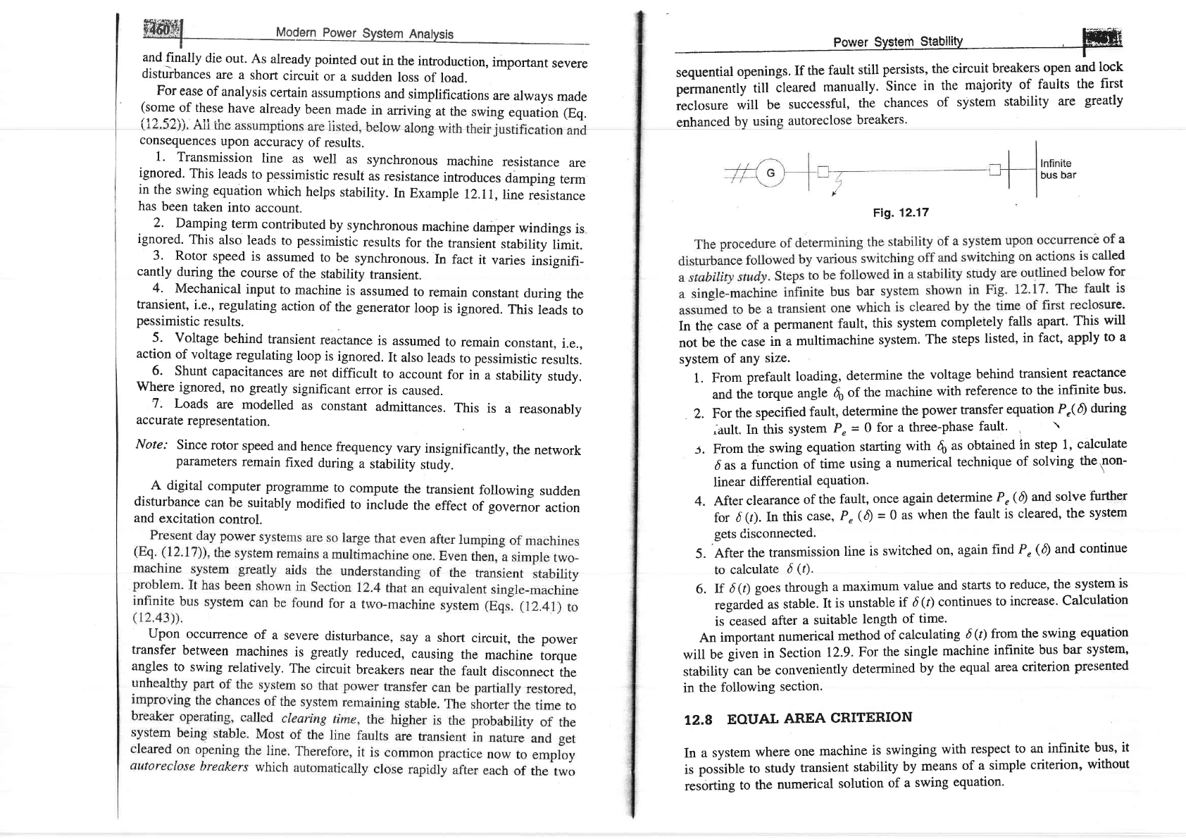
StabilitY ffiffi
p"rrnon.ntly
till
cleared
manually.
Since
in
the
majority
of
faults
the
first
ieclosure
will
be
successful,
the
chances
of
system
stability
are
greatly
enhanced
by using
autoreclose
breakers.
Fig.12.17
In the
case
of
a
perrnanent
fault,
this
system
completely
falls
apart.
This
will
not
be
the
case
in
a multimachine
system.
The
steps
listed,
in fact,
apply
to a
system
of
any
size.
1.
From
prefault
loading,
determine
the
voltage
behind
transient
reactance
and
the
torque
angle
16o of
the
machine
with
reference
to
the
infinite
bus.
2.
For
the
specified
fault,
determine
the
power transfer
equation
Pr(A
during
^ault.
In this
system
P"
=
0
for a
three-phase
fault'
'
'
From
the
swing
equation
starting
with
fi
as obtained
in step
1,
calculate
das
a
function
of
time
using
a numerical
technique
of
solving
thetnon-
linear
differential
equation.
After
clearance
of
the
fault,
once
again
determine
P,
(A
and solve
further
for
d
(r).
In
this
case,
P"(A
=
0
as
when
the
fault
is
cleared,
the
system
gets Cisconnected.
After
the
transmission
line
is
switched
on,
again
find
P"
(0
and
continue
to
calculate
d
(r).
If
6
(t)
goes through
a
maximum
value
and
starts
to
reduce,
the
system
is
regarded
as
stable.
It
is unstable
if
d(r)
continues
to
increase.
Calculation
is
ceased
after
a suitable
length
of
time.
An
important
numerical
method
of
calculating
d(t)
from
the swing
equation
will
be
giurn in
Section
12.9.
For
the
single
machine
infinite
bus
bar
system,
stability
can
be
conveniently
determined
by
the
equal
area
criterion
presented
in
the
following
section.
I2.8
EOUAL
AREA
CRITERION
In
a
system
where
one
machine
is
swinging
with respect
to an
infinite
bus,
it
is
possible
to
study
transient
stability
by
means
of
a simple
criterion,
without
resorting
to
the
numerical
solution
of a
swing
equation.
5.
4.
5.
6.
Consider
the
swing
equation
&rt
,"=
accelerating
power
d26
I
AF
=
*@^-
P'1
=
M=!
rf
ln pu
system
(r2.s3)
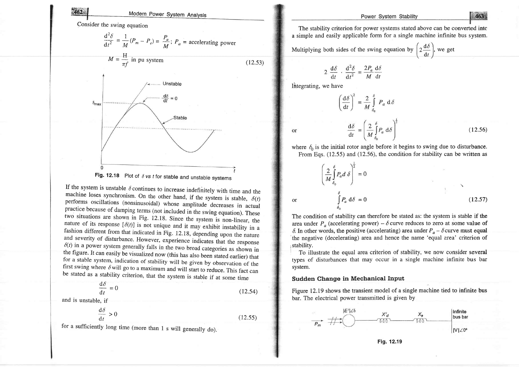
Fig.
12.1g
prot
of
6 vs
tfor
stabre
and
unstabre
systems
lf
the
system
is
unstable
dcontinues
to
increase
indefinitely
with
time
and
the
machine
loses
synchronism.
on
the
other
hand,
if
the
system
is
stable,
6(t)
performs
oscillations
(nonsinusoidal)
whose
amplitude
decreases
in
actual
praetice
because
of
darnping
terms (not
included
in
the
swing
equation).
These
two
situations
are
shown
in
nig.
12.1g.
since
the
system
is
non_linear,
the
nature
of
its
response
160l
is
not
unique
and
it
may
exhibit
instability
in
a
fashion
different
from
that
indicated
in
Fig.
rz.rg,depending
upon
the
nature
and
severity
of
disturbance.
However.
experience
indicates
ihai
the
response
6!'l
j"
a
power
system
generally
falls
in
the
two
broad
categories
as
shown
in
the
figure'
It
can
easily
be
visualized
now
(this
has
also
been
stated
earlier)
that
for
a
stable
system,
indication
of
stability
will
be given
by
observation
of
the
first
swing
where
dwill
go
to
a
maximum
and
will
Jturt
to
reduce.
This
fact
can
be
stated
as
a
stability
criterion,
that
the
system
is
stable
if
at
some
time
d6
=o
dt
and
is
unstable,
if
d6
--
>0
<lt
for
a
sufticiently
long
time (more
than
1
s
will
genera'y
do).
(r2.s4)
(12.ss)
Multiplying
both sides
of the swing
equation
*
[t#),
we
get
The stability criterion
for
power
systems stated above can be converted intc
a
simple and
easily applicable
form
for a single
machine
infinite
bus
system.
2P"
d6
Mdt
Ifrtegrating,
we have
(r2.s6)
where
do is
the initial
rotor
angle before
it
begins
to swing due to disturbance.
From Eqs.
(12.55)
and
(12.56),
the condition
for stability can be written as
6
or
[r"ad
-o
6,,
The
condition
of stability
can therefore
be stated
as: the system is stable
if the
areaunder
Po(accelerating
power)
-dcurve
reduces
to zero at
some
value
of
d
In other
words, the
positive
(accelerating)
area under Po- 6curve must
equal
the negative
(decelerating)
area
and hence the name
'equal
area' criterion
of
lstability.
To
illustrate
the
equal
area criterion
of
stability,
we
now consider several
types of
disturbances
that may
occur in a single
machine infinite bus bar
system.
Sudden
Change
in
Mechanical
Input
Figure
12.t9
shows
the transient
model of a single
machine tied to infinite
bus
bar. The
electrical
power
transmitted
is
given
by
(r2.s7)
-->
Pm
Infinite
bus bar
lvlr0o
Fig.
12.19