Литвин Ф.Л. Развитие технологии и теории зубчатых передач
Подождите немного. Документ загружается.


NASA RP–1406 23
11
1
1917
21
21
21
21
– – sin
– – cos
– cos
– sin
(.. )
()
() () ()
()
m
KKm
XK X K Em
XXEm
γ
γ
γ
γ
()
()
()
Ι
ΙΙ
Ι
II
II II
II
is two.
Taking into consideration that in matrix (1.9.17) the four respective determinants of the third order are equal
to zero, we obtain after transformations the relations
X
Em K
mKm
()
()
()
cos sin
cos sin
(.. )
Ι
=
−
()
+
21
1918
γγ
γγ
II
II
1–
21 21
X
Em K
mKm
()
()
()
cos sin
cos sin
(.. )
II
=
−
()
+
21
1919
γγ
γγ
Ι
Ι
1–
21 21
(4) By analyzing the system of equations (1.9.12), (1.9.18), and (1.9.19), we can conclude the following:
(1) The parameters X
(i)
K
(i)
(i =
Ι
, II) of the axes of meshing depend on the coordinates (x,y) of the contact
point of the surfaces and on the components of the surface normal (unit normal).
(2) Three equations relate four parameters of the axes of meshing. The solution for the parameters of the
axes of meshing is not unique, even when the point of tangency and the common normal to the contacting
surfaces are considered known. This means that for any instant of meshing, there is a manifold of the axes of
meshing. However, there are two particular cases of meshing when only a couple of the axes of meshing, but
not a manifold of such axes, exist and the parameters of the axes of meshing do not depend on the contact point
and the contact normal: case 1, where the rotation is performed between crossed axes and the surface of one of
the gears is the helicoid; case 2, where a helicoid is generated by a peripheral milling (grinding) tool whose
surface is a surface of revolution.
Case 1 has been applied in the analysis of the meshing of worm-gear drives with cylindrical worms, helicon
drives, face-gear drives with crossed axes, and some types of spiroid gear drives. Case 2 has been applied in
the generation of worms and helical gears by a peripheral cutting (grinding) disk.
Case 1 of axes of meshing.—The surface of one of the mating gears is a helicoid. To derive the parameters
of the axes of meshing, we apply equations (1.9.12) and (1.9.13) to (1.9.16) and require that the sought-for
parameters be independent with respect to the point of tangency of the mating surfaces.
In the case of a helicoid, we have the following relation (Litvin, 1968):
yn xn pn
xy z
−= (.. )1920
where p is the screw parameter of the helicoid.
Equations (1.9.20) and (1.9.12) yield
XK X K n X Kp X K pn
yz
() () ( ) ( ) () () ( ) ( )
––– (..)
ΙΙ Ι Ι
−
()
−
()( )
[]
=
II II II II
0 1921
Equation (1.9.21) shows that the parameters of the axes of meshing do not depend on components of the surface
normal if these relations are observed:
XK X K
() () ( ) ( )
(.. )
ΙΙ
=
II II
1922

24 NASA RP–1406
XKpX Kp
() () ( ) ( )
–– (..)
ΙΙ
=
II II
1923
Further derivations of X
(i)
, K
(i)
(i =
Ι
, II) are based on the application of equations (1.9.22) and (1.9.23) and
the system of equations (1.9.13) to (1.9.16). The procedure for deriving the parameters follows:
Step 1: Considering equations (1.9.22), (1.9.13), and (1.9.15), we obtain
XK X K E
() () ( ) ( )
– cot ( . . )
ΙΙ
==
II II
γ
1924
Step 2: Considering equations (1.9.14) and (1.9.16), we obtain after transformations
X pK X pK Em p m
yy
() () () ( ) ( ) ( )
sin ( cos ) ( . . )
ΙΙΙ
−
()
−−
()
=−−
ωω
II II II
21 21
1 1925
γγ
Equations (1.9.25), (1.9.23), and (1.9.13) yield
Em p m
XpK
mi,
ii
21 21
21
1
0 1926
sin ( )
sin ( ) ( . . )
() ()
γ
γ
−−
−
+==
Ι
II
Then, using equations (1.9.26) and (1.9.24), we obtain
K
E
p
m
m
K
E
p
ii() ()
cos
sin
cot
(.. )
()
−−
−
+=
2
21
21
1
0 1927
γ
γ
γ
Step 3: The final equations for the determination of parameters X
(i)
, K
(i)
of the couple of the axes of meshing
are
K
E
p
m
m
E
p
m
m
E
p
()
.
cos
sin
cos
sin
cot
(.. )
Ι
=−
−
+−
−
−
1
2
11
2
14
1928
21
21
21
21
2
05
γ
γ
γ
γ
γ
X
E
K
()
()
cot
(.. )
Ι
Ι
=−
γ
1929
K
E
p
m
m
E
p
m
m
E
p
()
.
cos
sin
cos
sin
cot
(.. )
II
=−
−
−−
−
−
1
2
11
2
14
1930
21
21
21
21
2
05
γ
γ
γ
γ
γ
X
E
K
()
()
cot
(.. )
II
II
=−
γ
1931
In the case of an orthogonal gear drive, we have γ = π/2. To determine the expression for X
(II)
= 0/0, we use
the Lopithal rule (Korn and Korn, 1968). Then, we obtain the following equations for the axes of meshing
parameters:
K
E
pm
()
(.. )
Ι
=−
1
1932
21
X
()
(.. )
Ι
= 0 1933
NASA RP–1406 25
x
f
x
f
r
p
r
p
z
f
z
f
O
f
, I
y
f
y
f
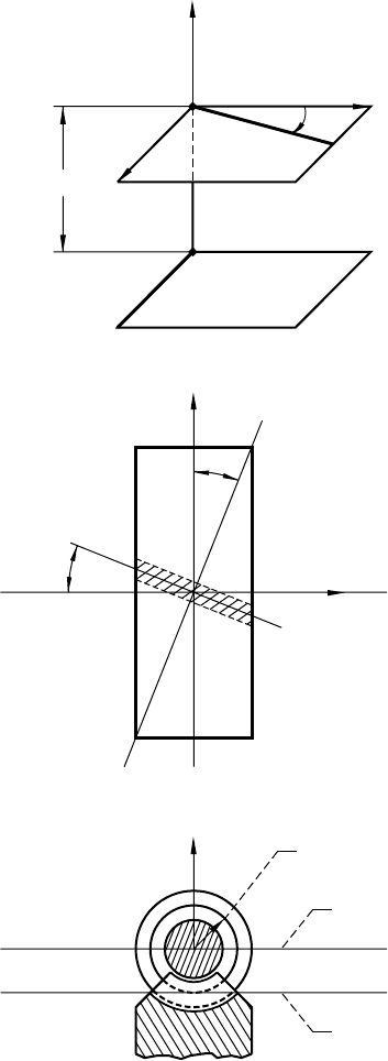
Figure 1.9.3.—Axes of meshing of orthogonal worm-gear
drive. (a) In three-dimensional space. (b) In orthogonal
projections.
Axis of meshing II
Axis of meshing I
II
II II
I
II
I
I
l
p
l
p
l
p
(a)
(b)
26 NASA RP–1406
x
f
x
f
r
p
z
f
z
f
y
f
y
f
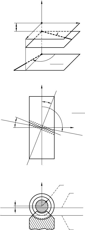
Figure 1.9.4.—Axes of meshing of nonorthogonal
worm-gear drive with right-hand worm. (a) In three-
dimensional space. (b) In orthogonal projections.
Axis of
meshing I
Axis of
meshing II
II
II
II
II
IIII
I
I
I
I
II
O
f
l
p
l
p
l
p
E cot g tan l
p
x
(I)
= – E cot g tan l
p
r
p
E cot g
(
(
cot
–1
r
p
E cot g
(
(
cot
–1
NASA RP–1406 27
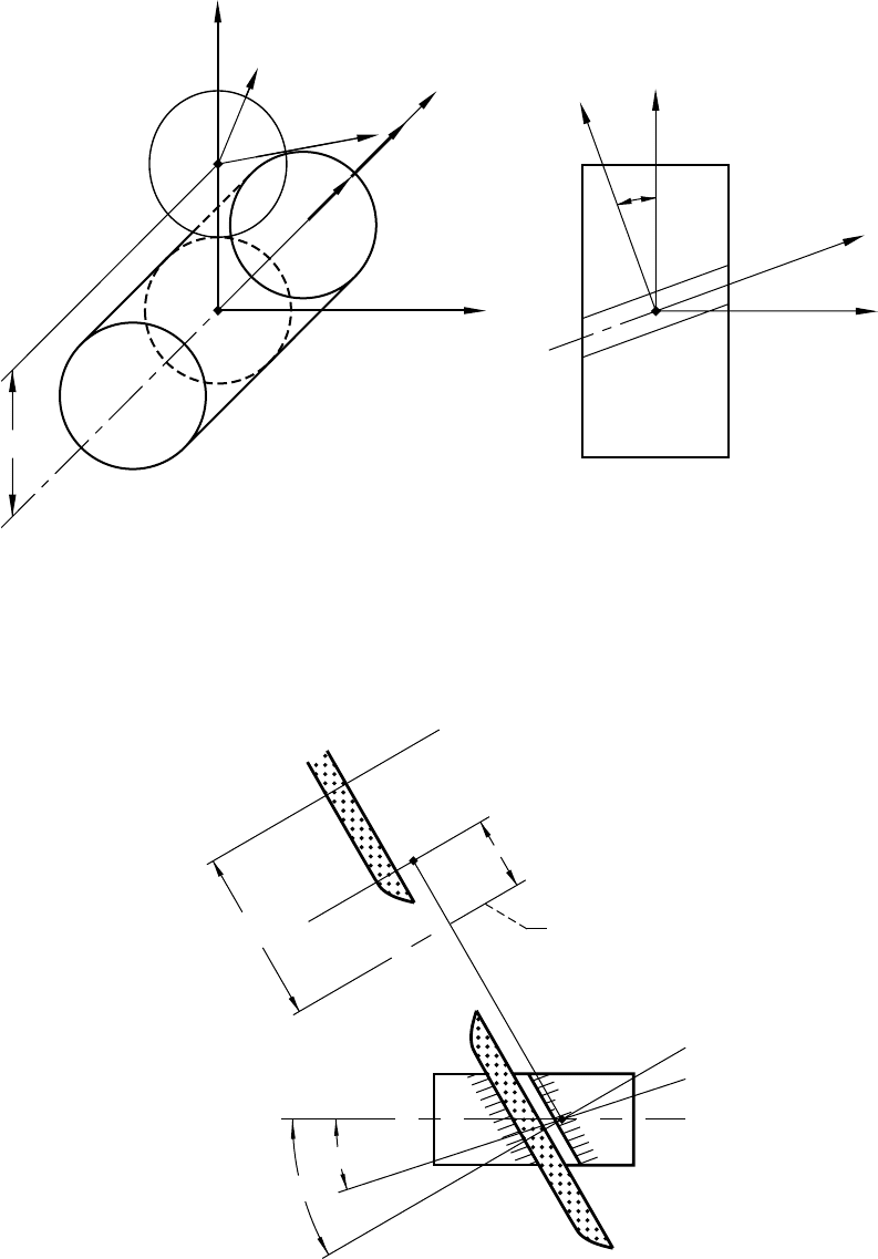
Figure 1.9.5.—Generation of worm by peripheral tool.
z
c
z
o
y
c
y
o
g
c
E
c
y
o
O
c
z
c
x
o
, x
c
y
c
z
o
O
o
v
pv
Figure 1.9.6.—Axes of meshing in case of helicoid
generation.
E
c
g
c
C
II
II
I
I
II
I
I
I
I
a
Worm axis
C
a
a
d

28 NASA RP–1406
K
()
(.. )
Π
= 0 1934
XE
p
m
()
(.. )
Π
=− −
21
1935
The axes of meshing for a worm-gear drive with a cylindrical worm are shown in figures 1.9.3 and 1.9.4.
For a face-gear drive with crossed axes and with a pinion as a spur gear, we have to take p = ∞.
In this case, all contact normals are perpendicular to the pinion axis, and one of the axes of meshing lies in
the infinity.
Case 2 of axes of meshing.—We will consider the generation of a helicoid by a cutting or grinding disk. The
installment of the tool is shown in figure 1.9.5. Coordinate system S
o
is rigidly connected to the frame. The
helicoid in the process of generation performs a screw motion about the z
o
-axis with the screw parameter p. We
may neglect the tool rotation since it is provided to obtain the desired cutting velocity and does not affect the
process of generation. Therefore, we may consider that systems S
c
and S
o
are rigidly connected during the
generation process. The crossing angle γ
c
between the z
c
- and z
o
-axes is usually equal to the lead angle λ
p
on
the helicoid pitch cylinder. The shortest distance is E
c
.
There are two axes of meshing in this case:
Ι
-
Ι
coincides with the tool axis; II - II lies in the plane that is
perpendicular to the shortest distance E
c
(fig. 1.9.6). The shortest distance between the helicoid axis and the axes
of meshing II - II is
aX p
c
==
o
()
cot ( . . )
II
γ
1936
1.10 Two-Parameter Enveloping
The motion of the generating surface
Σ
1
is determined with two independent parameters designated (
φ,ψ
),
and the family of surfaces
Σ
1
is represented in S
2
as
rMr
2211
1101(,,, ) (, ) , (. .)uu
θφψ φψ θ
=
()
The two equations of meshing for the case of two-parametric enveloping are determined as
Nv Nv
()
()
11
0 0 1102⋅= = ⋅= =
11
φ
ψ
θφψ θφψfu gu(,,, ) (,,, ) (. .),
Here, v
1
(
φ
)
; v
1
(12,
φ
)
, v
1
(
ψ
)
; v
1
(12,
ψ
)
represent the sliding velocity when the respective parameter of motion
(
φ
or
ψ
) is fixed. The subscript 1 in equations (1.10.2) indicates that the respective vectors are represented in
coordinate system S
1
.
The two-parameter method of enveloping was discussed in Litvin, Krylov, and Erikhov (1975) and Litvin
and Seol (1996). It can be successfully applied when the tool has a feed motion in the generation processes, such
as hobbing, shaving, and grinding. We have to emphasize that in reality the generation of surfaces with feed
motion is a one-parameter enveloping process because the two parameters of motion,
φ
and
ψ
, are related by
the generating function
ψ
(
φ
). Using one-parameter enveloping makes it possible to determine the real surface
Σ
2
* and its deviation from the theoretical envelope
Σ
2
and to evaluate the influence of the feed motion (of
function
ψ
(
φ
)).
A detailed example of two-parameter enveloping is presented in appendix C.
1.11 Localization of Contact and Simulation of Meshing of Gear Tooth
Surfaces
The localization of gear tooth surface contact is achieved when point contact instead of line contact of the
surfaces is provided. This enables one to reduce the sensitivity of the gear drive to misalignment and to also

NASA RP–1406 29
avoid so-called edge contact. The localization can be achieved by the mismatch of gear tooth surfaces. The
Gleason Works engineers have successfully developed spiral bevel gears and hypoid gears with point contact
of the surfaces. A localized contact is provided for circular-arc helical gears (Novikov-Wildhaber gears) and
can be achieved for other types of gear drives by gear tooth surface crowning.
We consider a great achievement to be the computerized simulation of meshing and of gear tooth surfaces
in point contact accomplished by applying TCA (Tooth Contact Analysis) computer programs. The simulation
of the meshing of gear tooth surfaces is based on the conditions of continuous tangency of gear tooth surfaces
that are represented by the following equations
rr
f
j
f
j
uq u q
() ()
(,,,) (,,,) (..)
1
111
2
222
1111
θφ θφ
=
nn
f
j
f
j
uq u q
() ()
(,,,) (,,,) (..)
1
111
2
222
1112
θφ θφ
=
Equations (1.11.1) and (1.11.2) indicate that the contacting surfaces have at the current point of tangency
common position vectors r
f
(i)
and surface unit normals n
f
(i)
, (i = 1,2). The coincidence of directions of the unit
normals for both surfaces can be provided by the proper order of cofactors in the cross products (∂r
f
(i)
/∂u
i
)
× (∂r
f
(i)
/∂
θ
i
), (i = 1,2). The gear tooth surfaces
Σ
1
and
Σ
2
are represented in the fixed coordinate systems S
f
where
the axes of gear rotation are located; (u
i
,
θ
i
) (i = 1,2) are the surface parameters;
φ
1
and
φ
2
are the angles of gear
rotation; q
j
(j = 1,2,...) designate the parameters of assembly.
Equations (1.11.1) and (1.11.2) yield a system of only five independent nonlinear equations (in six
unknowns) since
nn
ff
() ()
.
12
1==
These equations are represented as
fu u f C k
kk
111222
1
0 1 5 1 11 3,,,,, , , ( ,) (..)
θφ θφ
()
=∈ =
One of the unknowns, say
φ
1
, may be chosen as the input. Henceforth, we assume that equations (1.11.3) are
satisfied at a point
Pu u
0
1
0
1
0
1
0
2
0
2
0
2
0
1114=
()
,,,,, (..)
θφ θφ
and the Jacobian system at P
0
differs from zero. Thus,
∆
5
1234
5
11222
0 1 11 5=
()
()
≠
Df f f f f
Du u
,,,,
,,,,
(. .)
θθφ
From the theorem of the existence of the implicit function system, it follows that equations (1.11.3) can be
solved in the neighborhood of P
0
by functions
uu C
11 11 21 21 21
1
1116
φθφ φθφφφ
() () () () ()
[]
∈,,,, (..)
By using equations (1.11.1) and (1.11.2) and functions (1.11.6), we can determine the paths of contact on
surfaces
Σ
1
and
Σ
2
and the transmission function
φ
2
(
φ
1
). The gear misalignment is simulated by the variation
of assembly parameters q
j
that will cause the shift in the paths of contact and the deviations of
φ
2
(
φ
1
) from the
transmission function of an aligned gear drive. Note that a unique solution of equations (1.11.3) by functions
(1.11.6) exists only for the case of meshing by a point contact of surfaces. The Jacobian ∆
5
becomes equal to
zero when the surfaces are in line contact.
This method of simulating the meshing of misaligned gear drives was proposed by Litvin and Guo (1962).
We must credit The Gleason Works researchers who developed and applied in industry the TCA computer
programs for hypoid gear and spiral bevel gear drives. Similar programs were developed later by Litvin and
Gutman (1981).
The numerical solution of nonlinear equations (1.11.3) is an iterative process based on the application of
computer programs (Dongarra et al., 1979 and Moré, 1980).

30 NASA RP–1406
1.12 Equation of Meshing for Surfaces in Point Contact
The computerized simulation of the meshing of gear tooth surfaces described in section 1.11 does not require
knowledge of the equation of meshing. However, it is possible to prove that equation (1.2.7) can also be
extended to apply in the case of surfaces in point contact.
Consider an aligned gear drive when the assembly parameters are observed. The differentiation of equation
(1.11.1) yields
∂
∂
∂
∂θ
θ
∂
∂φ
φ
∂
∂
∂
∂θ
θ
∂
∂φ
φ
rrrr r r
fff f f f
u
u
tttu
u
ttt
() () () ( ) () ( )
(. .)
111 2 2 2
1121
111 2 2 2
d
d
d
d
d
d
d
d
d
d
d
d
111 2 2 2
++= + +
It is easy to verify that the derivatives (∂r
f
(i)
/∂u
i
), (∂r
f
(i)
/∂
θ
i
) (i = 1,2) lie in the common tangent plane for
surfaces in tangency. Using the scalar product of the common surface normal N
f
(i)
with both sides of equa-
tion (1.12.1), we obtain
∂
∂φ
φ
∂
∂φ
φ
rr
N
ff
f
i
tt
() ()
()
(. .)
12
0 1 12 2
12
d
d
d
d
12
−
⋅=
Taking into account that (∂r
f
(i)
/∂
φ
i
) (d
φ
i
/dt) is the velocity v
(i)
tr
of the surface point (in transfer motion with
the surface), we obtain
Nvv Nv
f
tr tr
ff
() () () () ( )
(. .)
11
⋅−
()
=⋅ =
12 12
0 1 12 3
This is the proof that the equation of meshing can also be applied for the case of the point contact of surfaces.
Similar derivations performed for a misaligned gear drive yield
N
rr r
f
ff f
j
j
q
q
()
() () ()
(. .)
1
12
ddd⋅−−
=
∂
∂φ
φ
∂
∂φ
φ
∂
∂
12 2
0 1 12 4
12
which allows us to investigate the influence of gear misalignment. However, this equation can be applied when
the theoretical line of action (the set of contact points in the fixed coordinate system) is known. The influence
of the misalignment errors can be determined directly by applying the TCA program.
1.13 Transition From Surface Line Contact to Point Contact
Instantaneous line contact of gear tooth surfaces may exist only in ideal gear drives without misalignment
and manufacturing errors. Such errors cause the gear tooth surfaces to contact each other at a point at every
instant instead of on a line. The set of contact points on the gear tooth surface forms the contact path. A current
point of the contact path indicates the location of the center of the instantaneous contact ellipse. (Recall that
because of the elastic deformation of the teeth, the contact is spread over an elliptical area.) The set of contact
ellipses represents the bearing contact, which covers only a certain part of the tooth surface instead of the entire
working tooth surface (in the case of the line contact of an ideal gear drive).
Our goals are to determine the following: (1) the contact path for a misaligned gear drive and (2) the
transmission errors caused by misalignment. Such problems are important for those gear drives whose gear
tooth surfaces are designed as mutually enveloping. Typical examples are a worm-gear drive with a cylindrical
worm and involute helical gears with parallel axes.
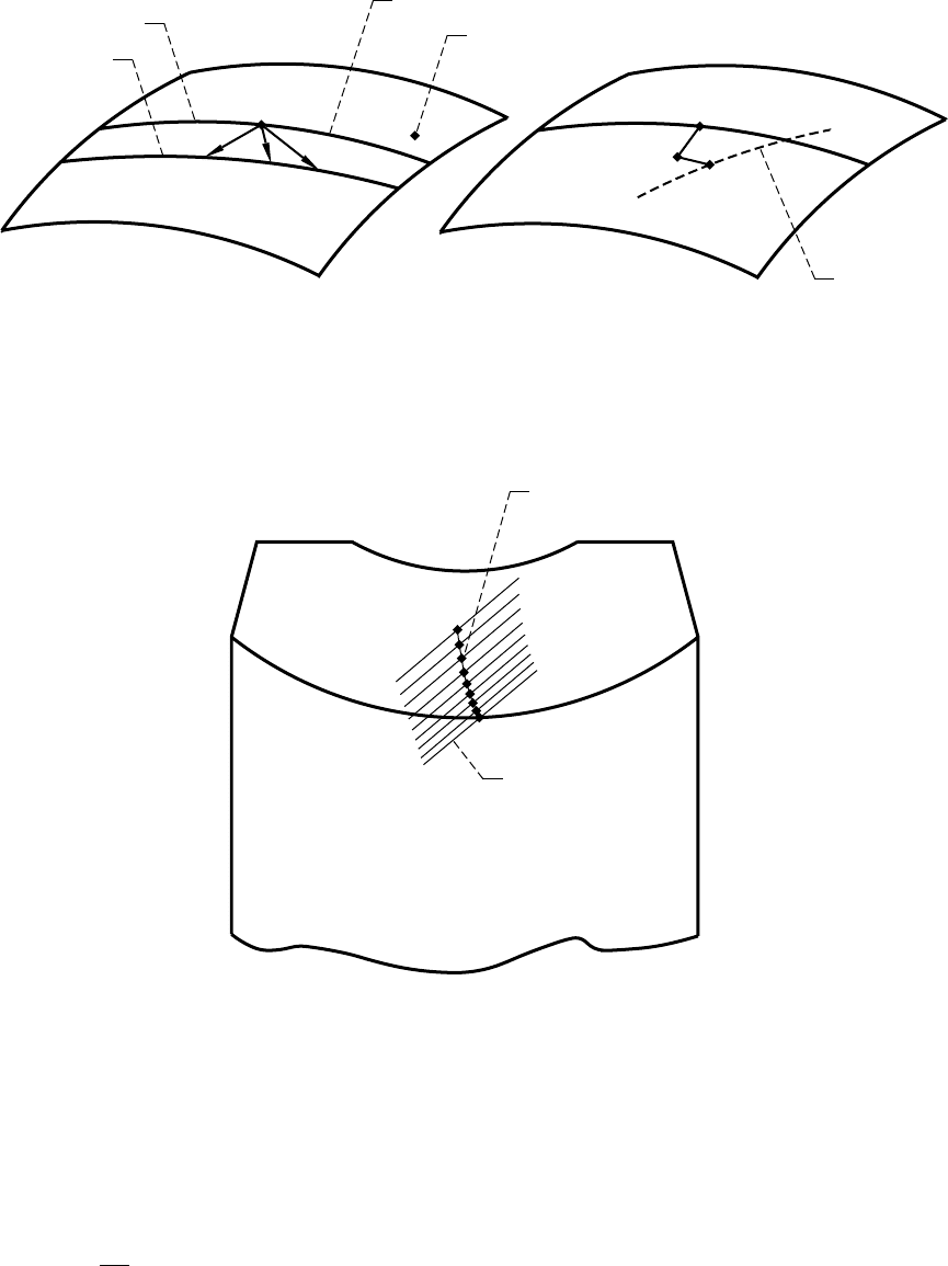
Figure 1.13.1(a) shows two neighboring contact lines L
1
(
φ
) and L
2
(
φ
+ d
φ
) on surface
Σ
1
of an ideal gear drive
without misalignment. Surface
Σ
1
is in instantaneous line contact with
Σ
2
; parameter
φ
is the generalized
parameter of motion, and point M is a current point of contact line L
1
(
φ
). The displacement from M to any point
on L
2
(
φ
+ d
φ
) can be performed in any direction if it differs from the tangent to line L
1
(
φ
) at M. However, in
the case of a misaligned gear drive with a point contact of surfaces
Σ
1
and
Σ
2
, we have to determine (1) the
transition point P on the contact line L
1
(
φ
) (fig. 1.13.1(b)) (the transfer from line contact of the surfaces to point
NASA RP–1406 31
contact will occur in the neighborhood of P) and (2) the current point P* of the real contact path. The direct
determination of P* is impossible because the Jacobian ∆
5
of the system of equations (1.12.3) of surface
tangency is equal to zero. Therefore, it becomes necessary to determine an intermediate point K in the
neighborhood of P (fig. 1.13.1(b)) where ∆
5
differs from zero. The determination of point K is based on the fact
that vector
PK
is collinear to the vector that passes through two neighboring transition points. An equation to
determine the transition point on a contact line L
1
(
φ
) was proposed in Litvin (1994) and Litvin and Hsiao (1993).
The Jacobian ∆
5
at point K differs from zero, and we can start the procedure of simulating the meshing of two
surfaces in point contact.
Figure 1.13.2 shows the shift in the bearing contact in a misaligned worm-gear drive. Transmission errors
due to misalignment will occur and may cause noise and vibration (see section 1.14).
Figure 1.13.1.—For derivation of transition point. (a) Representation of two neighboring contact lines.
(b) Transition from surface point P to P* via K.
(a) (b)
L
1
(f)
L
2
(f + df)
S
1
M
Contact line
K
P
P*
Path of
contact
points
Figure 1.13.2.—Contact path of misalignment of
worm-gear drive. Change of center distance,
DE = 0.5 mm; change of shaft angle, Dg = 5'.
Contact path
Major axis of
contact ellipse

32 NASA RP–1406
1.14 Design and Generation of Gear Drives With Compensated
Transmission Errors
Influence of Transmission Errors on Conditions for Transfer of Meshing
Experimental tests show that the level of noise and vibration depends on the level and shape of transmission
errors caused by gear misalignment. Henceforth, we will assume that the gear tooth surfaces are mismatched
and that they contact each other at every instant at a point. This precondition is important when designing low-
noise gear drives, but it must be complemented with the requirement that one apply the predesigned parabolic
function of transmission errors, which is represented as
∆φ φ φ
21 1
2
1141() (..)=−a
It will now be shown that the application of such a function allows one to absorb transmission errors caused
by gear misalignment, to avoid edge contact, and to improve the conditions for the transfer of meshing. Edge
contact means curve-to-surface contact that may occur instead of surface-to-surface contact. In such a case, the
curve is the edge of the gear tooth surface of one of the mating gears that is in mesh with the tooth surface of
the mating gear. The transfer of meshing means that the continuous transformation of motions by a gear drive
requires that a pair of teeth in mesh be changed for another pair.
Figure 1.14.1(a) shows that the transmission function
φ
2
(
φ
1
) for an ideal gear drive is linear and is represented
as
φφ φ
21
1
2
1
1142() (..)=
N
N
where N
1
and N
2
are the gear tooth numbers. The contact ratio (the number of teeth being in mesh
simultaneously) may be larger than 1 in an ideal gear drive. In reality, ideal gear drives do not exist because
alignment errors cause transmission errors that substantially worsen the conditions for the transfer of motion.
Figure 1.14.1(b) shows the transmission function
φ
2
(
φ
1
) for a misaligned gear drive that is a piecewise nonlinear
function for each cycle of meshing with worsened conditions for the transfer of meshing. The cycle of meshing
is determined with the angles of rotation of the driving and driven gear represented as
φ
1
= (2π/N
1
)
and
φ
2
= (2π/N
2
). The author and his fellow researchers at the University of Illinois investigated crowned involute
helical gears, double-circular-arc helical gears, and hypoid gears. They found that the function of transmission
errors ∆
φ
2
(
φ
1
) for misaligned gear drives usually has the shape shown in figure 1.14.2(a). The linear part of
∆
φ
2
(
φ
1
) is caused by gear misalignment; the nonlinear dashed part of ∆
φ
2
(
φ
1
) corresponds to the portion of the
meshing cycle when the edge contact occurs. The second derivative of ∆
φ
2
(
φ
1
), and therefore the acceleration
of the driven gear, makes a big jump at the transfer point A of the meshing cycle.
The author’s approach is directed at improving the conditions for the transfer of meshing and is based on the
application of a predesigned parabolic function (1.14.1) of transmission errors. Such a function is provided by
the proper modification of gear tooth surfaces or by the stipulation of specific relations between the motions
of the tool and the generating gear in the generation process. It will be shown next, that the simultaneous action
of both transmission error functions, the predesigned one and that caused by misalignment (in fig. 1.14.2(a)),
causes a resulting function of transmission errors that is again a parabolic function having the same slope as the
initially predesigned parabolic function. The magnitude ∆
φ
2max
of the resulting maximal transmission errors
(caused by the interaction of both functions shown in fig. 1.14.2(b)) can be substantially reduced. The level of
the driven gear accelerations is reduced as well, and an edge contact, as a rule, can be avoided.
The transmission function for the gear drive, when the predesigned parabolic function of transmission errors
is provided, is shown in figure 1.14.3(a). The predesigned parabolic function is shown in figure 1.14.3(b). It is
important to recognize that the contact ratio for a misaligned gear drive with rigid teeth is equal to 1. However,
the real contact ratio is larger than 1 because of the elastic deformation of the teeth. While investigating the
correlation between the predesigned function of transmission errors and the elastic deformation of teeth, we
have to consider the variation in the elastic deformation of the teeth during the meshing process, but not the
whole value of the elastic deformation. It is assumed that the variation in elastic deformation is comparable to
the level of compensated transmission errors.