Литвин Ф.Л. Развитие технологии и теории зубчатых передач
Подождите немного. Документ загружается.

NASA RP–1406 43
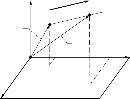
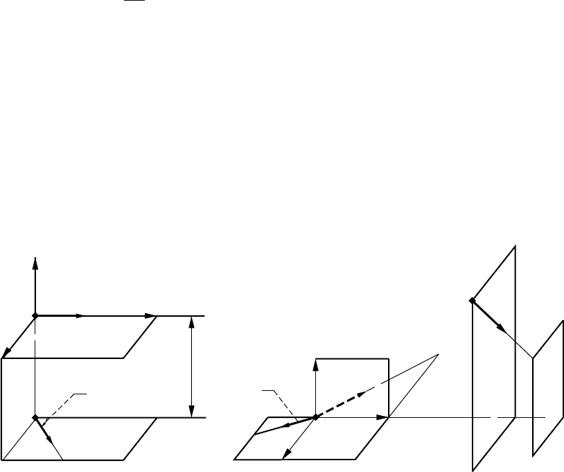
C.3 Pluecker’s Linear Complex for Straight Lines on a Plane
A plane may be determined by considering as given: (1) a point M
o
through which passes the plane and (2)
a normal N to the plane (fig. C.3.1).
A straight line that belongs to plane Π is represented as
r r a ( ) N a=
o
+≠⋅=
λλ
,(..)00 31C
Equations (C.3.1) yield
Nrr⋅
()
=–
o
032(..)C
and the plane may be represented by the equation
Nr⋅=d (..)C33
where N, r
o
, and consequently, d are given.
We consider now a line (g, m
g
), which belongs to the same plane if the following equation is observed
(Merkin, 1962):
Ngm gg⋅×
()
=⋅
()
g
d (..)C34
Direct transformations of equation (C.3.4) yield
N g m N g r g N rgg gNg Nrgg gg⋅×
()
=⋅××
[]
=⋅ ⋅− ⋅
[]
=⋅ ⋅= ⋅
g
d( ) ()( ) ()() (..)C35
We are reminded that N · g = 0 since g must lie in plane Π.
Considering lines (a, m
a
) and (g, m
g
), we can verify that the couple of lines intersect each other or they are
parallel if the following equation is observed:
am m g⋅+⋅=
ga
0(..)C36
The proof of this statement is based on the following:
(1) Direct transformations of equation (C.3.6) yield
Figure C.2.1.—Representation of straight line.
x
z
y
O
M
M
0
a
r
r
o
44 NASA RP–1406
ar r ag r r ag⋅×
()
+×
()
⋅= −
()
⋅×=
ga a
g
g
() (..)037C
(2) Equation (C.3.7) is observed if
(a) r
a
– r
g
= 0, a × g ≠ 0, which means that the lines have a common point.
(b) r
a
≠ r
g
, a × g = 0, which means that the two lines are parallel.
Equation (C.3.6) represents Pluecker’s linear complex of all lines (g, m
g
) defined by a given vector a and
couple (a, m
a
).
Line (g, m
g
) has six Pluecker’s coordinates (g
x
, g
y
, g
z
, m
gx
, m
gy
, m
gz
), but only three are independent
because a line has only four independent Pluecker’s coordinates and an additional relation between the
coordinates is provided by equation (C.3.6).
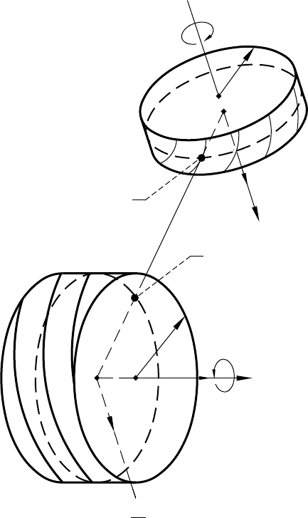
C.4 Application to Screw Motion
Screw Motion
We consider the rotation of two gears about crossed axes. The relative motion may be determined as the screw
motion represented by vector ω
s
and moment m
s
= pω
s
(fig. C.4.1). Here, ω
s
and m
s
are the angular velocity
of rotation about and translation along the instantaneous axis of screw motion; p is the screw parameter.
Two coordinate systems S
1
and S
2
are rigidly connected to gears 1 and 2. Let us say that gear 1 is movable
whereas gear 2 is held at rest. Point M of gear 1 will trace out in S
2
(in infinitesimal motion) the small arc of a
helix. The velocity v of point M of gear 1 with respect to point M of gear 2 may be represented by vector equation
vr=×+ωωωω
ss
p (..)C41
where r is the position vector of point M. Two components of v represent the velocities in rotation about and
translation along the screw axis.
Figure C.3.1.—Representation of straight lines on a plane.
y
z
x
O
M
M
0
g
N
NASA RP–1406 45
Helix and Trihedron τ, b, and c
The velocity v is directed along the tangent τ to the helix. Tangent τ and the screw axis form the angle
(90° –λ) (fig. C.4.1) where
tan ( . . )
λ
ρρ
==
p
p
s
s
ω
ω
C42
and
ρ
is the shortest distance of point M from the axis of screw motion.
The helix on a cylinder with radius
ρ
is represented as
r( ) cos( ) sin( ) ( . . )
θρθ ρθ θ
=+ +
[]
qqp C43
where
θ
is the varied helix parameter; q and
θ
= 0 determine in plane z = 0 the location of the helix reference
point. The vector field of velocity v may be determined as the family of tangents to helices that are traced out
on coaxial cylinders of various radii
ρ
. Any one of the family of helices is a spatial curve. A small arc of the
helix is traced out in S
2
by point M of S
1
, and it belongs to the osculating plane formed by tangent
τ
to the helix
and the principal normal c to the helix (fig. C.4.2).
Trihedron τ, b, and c is formed by tangent τ to the helix, binormal b, and principal normal c (see definitions
in Favard, 1957; Litvin, 1994). The unit vectors of the trihedron are represented by
ττ= =
×
×
=×
r
r
b
rr
rr
cb
θ
θ
θθθ
θθθ
τ
, , ( . . )C44
After derivations, we obtain
ττ
=
−+
+
sin ( )cos
cos ( )cos
sin
(..)
θλ
θλ
λ
q
q C45
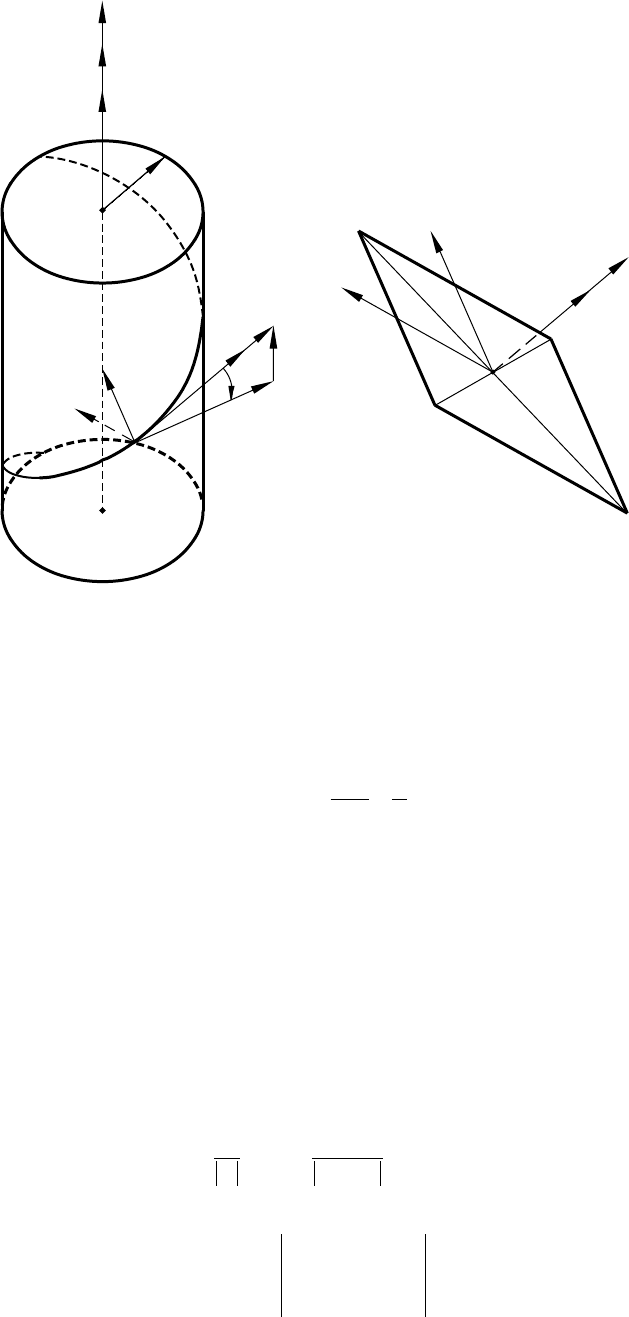
Figure C.4.1.—Presentation of relative velocity in screw motion. (a) Helix and trihedron t, b,
and c. (b) Null plane.
(a)
(b)
Null plane (P)
c
b
t
v
M
pm
s
l
v
M
O
c
b
t
r
v
s
Axis of screw motion
46 NASA RP–1406
b =
+
−+
sin sin( )
sin cos( )
cos
(..)
λθ
λθ
λ
q
q C46
c =
−+
−+
cos( )
sin ( ) ( . . )
θ
θ
q
q
0
47C
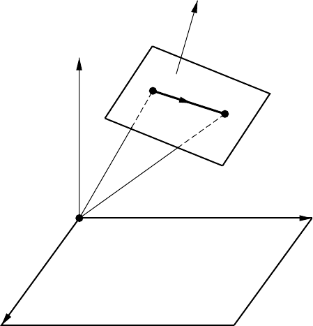
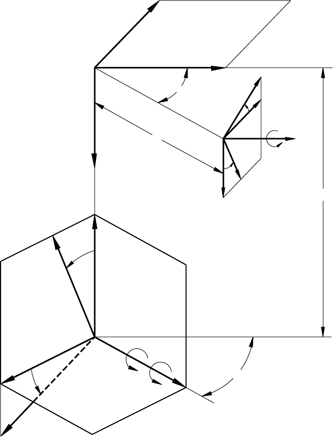
Null Plane, Null Axes, and Linear Complex in Screw Motion
We choose in coordinate system S
2
a point M and determine the velocity v of point M of coordinate system
S
1
with respect to the screw motion by using equation (C.4.1). Then, we determine plane Π that passes through
M and is perpendicular to v (fig. C.4.1(b)). Plane Π is called the null plane of point M and vice versa, and point
M is called the null point (pole) of Π. Plane Π contains straight lines (g, m
g
) that pass through pole M. In
accordance with the definition of plane Π, we have
vg⋅=048(..)C
Equations (C.4.8) and (C.4.1) yield
mg m
ssg
⋅+ ⋅ =ωω 049(..)C
where m
s
= pω
s
, m
g
= r × g =
OM
× g. Equation (C.4.9) may be called Pluecker’s linear complex for screw
motion.
Any straight line (g, m
g
) through M that belongs to null plane Π is called a null axis. Particularly, the binormal
to the helix is also a null axis.
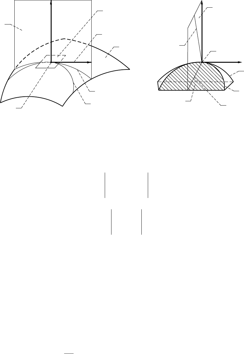
Figure C.4.2.—Illustration of orientation of null plane. (a) Normal plane and tangent plane. (b) Null plane
and osculating plane.
(a) (b)
Tangent
plain
Normal
plain
L
p
L
s
M
S
t
N
Null plain
Binormal
Osculating plane
M
L
p
L
s
t
N
Principal
normal
NASA RP–1406 47
C.5 Interpretation of Equation of Meshing of One-Parameter
Enveloping Process
The basic form of the equation of meshing (see section 1.2) is represented by
Nv
i
i
if⋅= =
()
( , , ) ( . . )
12
012 51C
where N
i
is the common normal to the contacting surfaces and v
i
(12)
is the relative velocity. The scalar product
of vectors is invariant to the applied coordinate systems S
1
, S
2
, and S
f
that are rigidly connected to gears 1, 2,
and the frame, respectively. Equation (C.5.1) is obtained from the conditions of tangency of the generating and
enveloping surfaces.
The application of the concept of Pluecker’s linear complex enables one to illustrate the equation of meshing
in terms of the null axis and the null plane and the orientation of the normal N in the null plane. We now introduce
two approaches for determining Pluecker’s linear complex.
Approach 1. Since normal vector N to the contacting surfaces is perpendicular to the relative velocity v
s
, the
normal (N, m
N
) belongs to the null plane, and an equation similar to (C.4.9) yields the linear complex
mN m
ssN
⋅+ ⋅ =ωω 052(..)C
where m
s
= pω
s
and m
N
=
OM
× N.
The orientation of the normal (N, m
N
) in the null plane is shown in figure C.4.2.
Approach 2. The concept of using screw motion for the determination of relative velocity was presented in
Approach 1 and in section C.4. We have considered as well that coordinate system S
1
rigidly connected to gear
1 performs a screw motion with respect to coordinate system S
2
rigidly connected to gear 2 while S
2
and gear
2 are held at rest. However, this concept is not the primary one to be used in kinematics and in the theory of
gearing. The following derivations of Pluecker’s linear complex are based on the concept that both gears
perform rotations about their axes as shown in figure C.5.1. The derivation procedure follows:
Step 1: Rotation about crossed axes is performed with angular velocities ω
(1)
and ω
(2)
as shown in fig-
ure C.5.1(a). By substituting –ω
(2)
with an equal vector that passes through O
f
and a respective vector moment
m
ω
, we obtain the velocities in relative motion (fig. C.5.1(b)):
Figure C.5.1.—Representation of normal to contacting surfaces as the null axis. (a) Applied coordi-
nate system and vectors v
(1)
and v
(2)
of angular velocities. (b) Relative angular velocity v
(12)
,
vector m
v
and surface normal N.
(a) (b)
O
2
x
f
v
(1)
v
(2)
E
y
f
O
f
z
f
g
x
f
m
v
v
(12)
M
N
y
f
O
f
z
f

48 NASA RP–1406
ωωωωωωωωωωωω=− =×−
()
≡
()
() () () ( )
, , ( . . )
12 2 12
53mE
ω
C
where E =
OO
f
2
.
Step 2. It is known from differential geometry and the theory of gearing that the generating surface and the
envelope are in line contact at every instant. Figure C.5.1(b) shows that point M is a point of the line of contact,
N is the common normal to the contacting surfaces at M, and r =
OM
f
is the position vector of M.
The normal as a straight line may be represented by the direction vector N and the respective vector moment
m
N
. Thus, we consider as given
NmrN, ( . . )
N
=× C54
If (N, m
N
) belongs to Pluecker’s linear complex, the following equation must be observed:
mNm
ω
⋅+ ⋅=
N
ωω 055(..)C
Equations (C.5.3) to (C.5.5) yield
−×
()
⋅+× ⋅=ENrNωωωω
()
() (..)
2
056C
After transformations of equation (C.5.6), we obtain
NrE Nv⋅×
()
−×
()
[]
=⋅ =ωωωω
() () ()
(..)
12 2 12
057C
Equation (C.5.7) is observed since it is the equation of meshing of the contacting surfaces. This means that
N is the null axis.
Using Pluecker’s terms, we can determine the null plane as the one that passes through contact point M,
contains the normal N, and is perpendicular to the moment.
mE r rE*(..)
() () () () () ()
=− ×
()
+−× −
()
[]
=−
()
×− ×
()
ωωωωωωωωωωωω
21212 2
58C
It is evident that m* = v
(12)
, which means that the null plane is perpendicular to the relative velocity v
(12)
.
The drawings of figure C.4.2(a) illustrate the concept of planar L
p
and spatial L
s
curves located on a tooth
surface. Both curves are in tangency at point M and their common unit tangent is designated
τ
. These drawings
also show the tangent plane to surface
Σ
at point M.
The drawings of figure C.4.2(b) represent in an enlarged scale curves L
p
and L
s
. For the case of the meshing
of the envelope and the generating surface, spatial curve L
s
is the trajectory that is traced out in relative motion
by point M of the moving surface on the surface held at rest. The relative motion is a screw motion (see section
C.4), and the relative velocity is directed along the tangent to the helix at point M that coincides with the unit
tangent
τ
shown in figure C.4.2(b). The null plane at any point M of the tangency of the envelope and the
generating surface can be determined as follows. Consider as known at point M the common normal N to the
surfaces and the vector of relative velocity or its unit tangent
τ
. Then, the null plane at point M is determined
to be the plane that passes through normal N and is perpendicular to
τ
, the unit vector of relative velocity
(fig. C.4.2(b)). We are reminded that the null plane also contains the binormal and the principal normal to the
trajectory L
s
at point M.
NASA RP–1406 49
C.6 Interpretation of Equations of Meshing of Two-Parameter
Enveloping Process
Introduction
In a two-parameter enveloping process, the generated surface is determined to be the envelope of the two-
parameter family of surfaces (Litvin, Krylov, and Erikhov, 1975; Litvin and Seol, 1996).
The generation of an involute helical gear with a grinding worm is used to illustrate the two-parameter
enveloping process. The method of grinding the spur and the helical gears with a cylindrical worm and the
grinding equipment were developed by the Reishauer Corporation. The meshing of the worm with the gear
being ground may be considered as the meshing of two involute helicoids with crossed axes (Seol and Litvin,
1996a).
Figure C.6.1 shows the grinding worm and the gear to be ground and the shortest distance between the axes
as the extended one (for the simplification of the drawings). The machining center distance is installed as
Err
wg pw pg
=+ (..)C61
where r
pw
and r
pg
are the radii of the pitch cylinders of the worm and the gear. With such a center distance, points
M
1
and M
2
of the pitch cylinders will coincide with each other and the pitch cylinders will be in tangency.
Figure C.6.1.—Representation of grinding of helical
gear by worm.
r
pw
r
pg
M
2
M
1
v
g
v
w
dt
dc
Z
w
Z
g
Grinding worm
Helical gear
50 NASA RP–1406
Figure C.6.2 shows the coordinate systems applied to describe the generation process. The movable
coordinate systems S
w
and S
g
are rigidly connected to the worm and the gear, respectively. Coordinate systems
S
m
, S
f
, and S
n
are fixed.
For the case when the worm and the gear are both right hand, the crossing angle
γ
wg
between the axes of the
worm and the gear is represented by
γλλ
wg pw pg
=+ (..)C62
where
λ
pi
(i = w,g) is the lead angle on the pitch cylinder.
The process of gear generation requires two independent sets of motion:
(1) The first set of motions is executed as the rotation of the gear and the worm about axes z
g
and z
w
,
respectively, with angular velocities
ω
(g)
and
ω
(w)
related by
Figure C.6.2.—Coordinate systems for grinding of helical gear by worm.
Y
g
Y
n
Z
g
Z
n
E
wg
X
n
Z
m
X
g
X
m
X
f
X
w
Z
w
Y
w
Y
m
Y
f
Z
f
V
(g)
v
(g)
g
wg
f
g
f
g
f
w
f
w
g
wg
O
n
, O
g
O
m
O
f
O
w
c
v
(w)

NASA RP–1406 51
ω
ω
()
()
(..)
w
g
g
N= C63
It is assumed that a one-thread grinding worm will be used; N
g
is the number of the gear teeth.
(2) The second set of motions is executed as the translation of the worm with the velocity dψ
(w)
/dt in the
direction
OO
mw
, which is parallel to the gear axis, and the additional rotation of the gear with the angular
velocity Ω
(g)
. Here,
d
dt
ψ
Ω
()
()
(..)
w
g
g
p= C64
where p
g
is the gear screw parameter (p
g
> 0 for a right-hand gear). The second set of motions dψ
(w)
/dt and Ω
(g)
is required to provide the feed motion during the grinding process.
Derivation of Gear Tooth Surface
The gear tooth surface
Σ
g
is an envelope of the two-parameter family of worm thread surfaces and is
determined by the following equations (Litvin, Krylov, and Erikhov, 1975):
rMr
ggww
uu(,,, ) (, ) (, ) (..)
θφψ φψ θ
= C65
Nv
i
w
i
wg
()
(..)⋅=
(,)
φ
066C
Nv
i
w
i
wg
()
(..)⋅=
(,)
ψ
067C
where (u,
θ
) are the surface parameters of the worm thread surface
Σ
w
;
φ
and
ψ
are the generalized parameters
of motion of the two sets of independent motions mentioned above; r
g
(u,
θ
,
φ
,
ψ
) is the vector function that
determines in S
g
the two-parameter family of surfaces
Σ
w
generated in S
g
; v
(wg,
φ
)
is the relative velocity that
is determined when the variable is the parameter of motion
φ
and
ψ
is held at rest; v
(wg,
ψ
)
is the relative velocity
in the case when the variable is the parameter of motion
ψ
and
φ
is held at rest; (C.6.6) and (C.6.7) are the
equations of meshing and the subscript i = g,n,m,f,w indicates that the respective scalar product of vectors is
invariant to the applied coordinate system.
Equations (C.6.5) to (C.6.7) represent the sought-for tooth surface by four related parameters.
Interpretation of Equations of Meshing by Application of Pluecker’s Linear Complexes
The transformation of the equation of meshing (C.6.6) is based on the following:
(1) The gear and the worm perform rotational motions about the crossed z
w
- and z
g
-axes with angular
velocities ω
(w)
and ω
(g)
, respectively (fig. C.6.2). Vectors of the scalar product are represented in the S
f
coordinate system.
(2) The relative velcoity v
(wg,
φ
)
is represented as
vr
f
wg
f
w
f
g
ff
g
g
OO
(,)
φ
=−
()
×− ×ωωωωωω
()
()
()
(..)C68
Then we obtain the following equation of meshing (C.6.6):
ωωωωωω
f
w
f
g
ff
g
g
f
w
OO
()
()
()
(..)−
()
×− ×
[]
⋅=rN
()
069C
where r
f
is the position vector of the point of tangency of surfaces
Σ
w
and
Σ
g
.
We interpret the equation of meshing (C.6.9) by Pluecker’s linear complex using the following procedure:
Step 1: The relative motion during generation is represented by vector
ω
and moment m
ω
that are represented
as
52 NASA RP–1406
ωωωωωωωωωω
=−= =−×
() () (,) ()
( . . )
wgwg
f
g
g
OO, m
ω
C610
Step 2: The common normal N to the contacting surfaces and the moment m
N
of N represented as
mNrN
N
ff
OM=×=× (.. )C611
are related to
ω
and m
ω
by the equation of the linear complex
ωω
⋅+⋅mmN
N
ω
=0 ( . . )C612
Equation (C.6.12) yields the equation of meshing (C.6.9). The null plane passes through the point of tangency
M, contains the normal N, and is perpendicular to v
(wg,
φ
)
. The normal N is the null axis of the linear complex
(see section C.3).
Let us now consider the interpretation of the equation of meshing (C.6.7) by application of Pluecker’s linear
complex. The second set of the paremeters of motion is represented by the couple of vectors (
Ω
,m
Ω
), which
can be obtained from equations that relate the motion of the worm with respect to the gear. Here,
ΩΩΩΩΩΩΩΩ
=−=−
() () ()
ω
gg
(.. )C613
since
Ω
(w)
= 0,
m
Ω
=
d
d
ψ
()
(.. )
w
t
C614
The other couple of vectors is represented by
Nm,
N
where m
N
is represented by equation (C.6.11).
Both couples of vectors are related by the equation of the linear complex:
ΩΩ
⋅+⋅=mmN
N
Ω
0615(.. )C
that yields
−⋅×
()
+⋅=
ΩΩ
()
()
(.. )
g
f
w
t
rN N
d
d
ψ
0616C
Equation (C.6.16), after simple transformations, may be represented as
−×+
⋅=
ΩΩ
()
()
(.. )
g
f
w
t
rN
d
d
ψ
0617C
Equations (C.6.17) yields
vN
f
wg
f
(w)
(,)
(.. )
ψ
⋅=0618C
The null plane for the second set of parameters of motion passes through the same point M and is
perpendicular to v
(wg,
ψ
)
but not to v
(wg,
φ
)
. The common surface normal N is the null axis of the second linear
complex.