Литвин Ф.Л. Развитие технологии и теории зубчатых передач
Подождите немного. Документ загружается.

NASA RP–1406 53
Chapter 2
Development of Geometry and Technology
2.1 Introduction
Errors in gear alignment and manufacture may shift the bearing contact, turn it into edge contact, and cause
transmission errors that, as we are reminded, are the main source of vibration. The purpose of this chapter is
to present the latest developments in gear geometry and technology directed at improving bearing contact and
reducing transmission errors.
The main errors of alignment and manufacture are as follows: the error of the shaft angle, the shortest center
distance, the leads in the case of helical gears, the errors in machine-tool settings (errors of orientation and
location of the tool with respect to the gear being generated), and the errors of the circular pitches. In addition,
we have to take into account the deflection of the teeth and shafts under load. To avoid or at least to reduce such
defects, it becomes necessary to substitute the line contact of the gear tooth surfaces by the point contact and
then, in addition, to modify the gear tooth surfaces. The modification of gear geometry is based on the proper
deviation of the gear tooth surfaces from the theoretical ones. The surface deviation can be provided (1) in the
longitudinal direction with the contact path in the profile direction (the direction across the tooth surface) and
(2) in the profile direction with the longitudinal direction of the contact path. In some cases, both types of
deviation must be provided simultaneously, but one of them must be the dominant.
The desired modification of gear geometry becomes possible by applying inventive methods of gear
technology such as (1) the mismatch of tool surfaces for the generation of spiral bevel gears and hypoid gears,
(2) the varied plunge of the tool for the generation of spur and helical gears, (3) the application of an oversized
hob for the generation of worm gears. Some of these examples are considered in the following sections. We
emphasize that in all of such cases of gear manufacture, it is important to provide a predesigned parabolic
function of transmission errors and to reduce their magnitude (see section 1.14), which will improve the
conditions of the transfer of meshing while one pair of teeth is changed for the neighboring one.
This chapter summarizes the developments achieved at the Gear Research Laboratory of the University of
Illinois at Chicago. Details are given in Litvin and Kin (1992); Litvin and Hsiao (1993); Litvin and Lu (1995);
Litvin et al. (1995, 1996a, 1996b); Litvin, Chen, and Chen (1995); Litvin and Feng (1996, 1997); Litvin, Wang,
and Handschuh (1996); Litvin and Seol (1996); Seol and Litvin (1996a, 1996b); Zhang, Litvin, and Handschuh
(1995); and Litvin and Kim (1997).
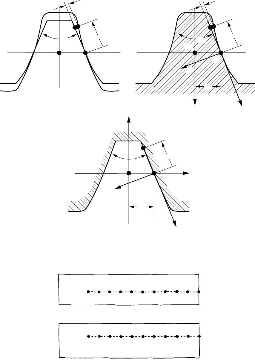
2.2 Modification of Geometry of Involute Spur Gears
Localization of Contact
Spur gears are very sensitive to the misalignment of their axes, which causes an edge contact. The sensitivity
of the gear drive to such a misalignment can be reduced by localizing the bearing contact. The localization of
the contact as proposed in Litvin et al. (1996b) can be achieved by plunging the grinding disk in the generation
of the pinion by form-grinding (fig. 2.2.1). The mating gear is generated as a conventional involute gear. The
plunging means that during the pinion generation, the shortest distance between the axes of the grinding disk
and the pinion will satisfy the equation (fig. 2.2.1)
54 NASA RP–1406
EE al
o
dd
−−
2
221(..)
where E and E
o
are the current and nominal values of the shortest distance, a
d
is the parabola coefficient of
function E(l
d
), and l
d
is the displacement of the disk in the direction of the pinion axis. The localized bearing
contact is shown in figure 2.2.2.
The same results can be obtained by varying the shortest distance between the hob (grinding worm) and the
generated spur or helical pinion. This variation is based on the application of an equation that is similar to
equation (2.2.1).
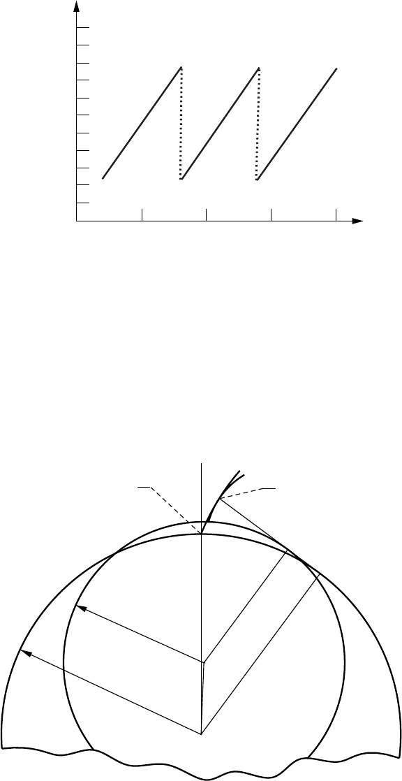
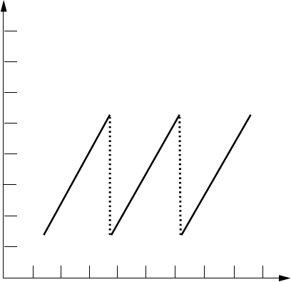
Transformation and Reduction of Transmission Errors
The profile of the pinion cross section for l
d
= 0 coincides with the axial profile of the disk. If the axial profile
of the disk is designed as the involute profile of the conventional pinion, the gear drive is still sensitive to
misalignment
∆α
and the error of tooth distance, which will cause an almost linear discontinuous function of
the transmission errors with the period of the meshing cycle
φ
1
= 2
π
/N
1
(fig. 2.2.2). Applying a predesigned
parabolic function enables the absorbtion of the transmission error linear functions shown in figure 2.2.3 (see
section 1.14).
The predesign of the parabolic function of the transmission errors is based on the following alternative
approaches: (1) changing the curvature of the pinion or the gear and (2) executing a nonlinear function that
relates the rotational motion of the gear (or the pinion) and the translation of the imaginary rack-cutter used to
generate the gear (or the pinion).
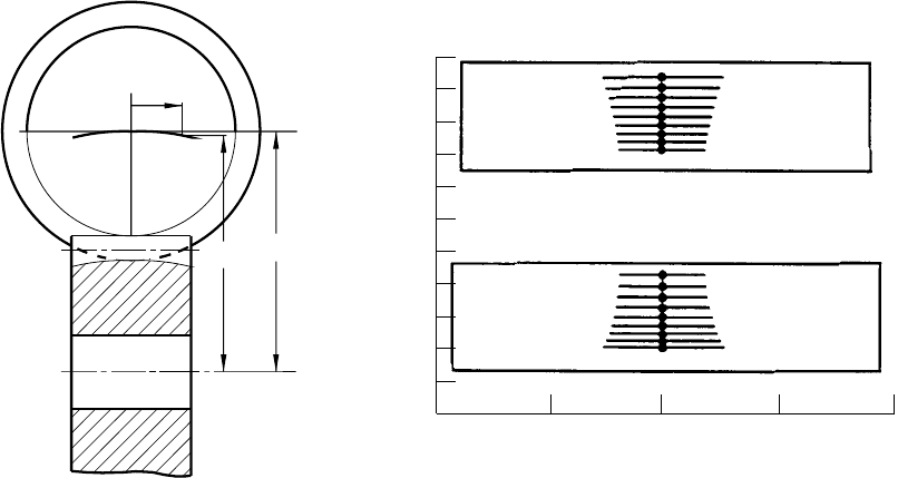
Changing the curvature of the pinion can be achieved by substituting the tooth involute profile that
corresponds to the theoretical base circle of radius r
bl
by an involute profile of radius r'
bl
(fig. 2.2.4).
Pinion
Gear
Tooth height
Tooth width
Figure 2.2.2.—Path of contact and bearing contact
of aligned gear drive with modified geometry.
–2 –1 0 1 2
Figure 2.2.1.—Form-grinding of pinion
by a plunging grinding wheel to satisify
E = E
o
– a
d
l
d
2
, where E and E
o
are the
current and nominal values of the shortest
distance, a
d
is the parabola coefficient of
function E(l
d
), and l
d
is the displacement
of the disk in the direction of the pinion
axis.
E
E
o
l
d
Pinion
Grinding
wheel
NASA RP–1406 55
M
M
o
r
b1
Figure 2.2.4.—Theoretical and modified profiles of spur pinion.
r
b1
'
Pinion rotation, f
1
, deg
Transmission error, Df
2
, arc sec
Figure 2.2.3.—Transmission errors caused by errors of
pressure angle Da = 3 arc min.
–10
–4
–3
–2
2
1
0
–1
3
4
5
6
7
0102030
56 NASA RP–1406
2.3 Modification of Involute Helical Gears
Computerized Investigation of Misaligned Conventional Involute Helical Gears
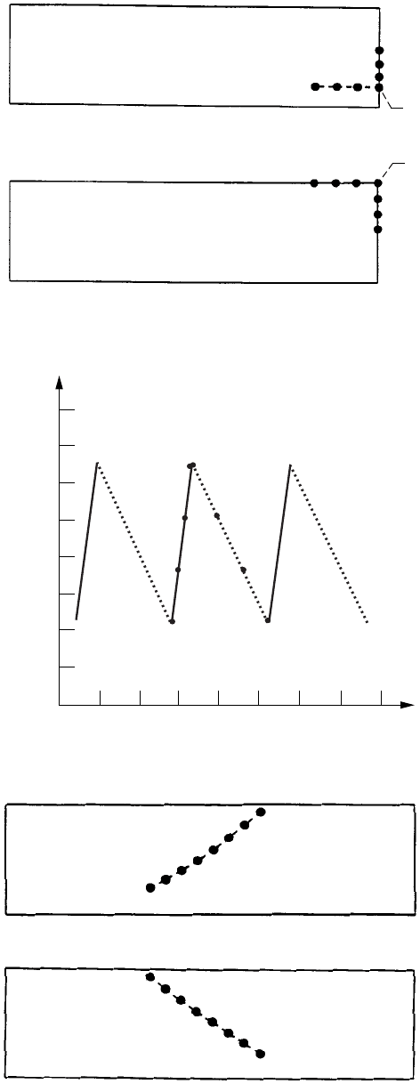
Aligned involute helical gears are in line contact at every instant, as shown in figure 2.3.1. Misalignment
caused by changes in the shaft angle, the lead, and the normal profile angle of one of the mating gears causes
edge contact instead of surface-to-surface tangency. Edge contact means tangency of the edge of one gear with
the tooth surface of the mating gear (see section 1.11). The edge and the surface are in mesh at every instant at
a point instead of on a line. An example of an edge contact caused by the change of the shaft angle
∆γ
or the
change of the pinion lead angle
∆λ
p1
is shown in figure 2.3.2. The edge contact caused by
∆γ
or
∆λ
p1
is also
accompanied by transmission errors, as shown in figure 2.3.3. However, the change in the normal profile angle
does not cause transmission errors, only an edge contact.
In the case of a change in the center distance E, the gear tooth surfaces are still in a line contact similar to those
shown in figure 2.3.1. However, an error in
∆
E causes a change in the backlash and in the pressure angle of the
gear drive.
There is a mistaken impression that a change in the lead is sufficient to shift the bearing contact from the edge
to the central position and avoid transmission errors. Our investigation shows that a combination of
∆γ
- and
∆λ
p1
-errors will enable one to avoid transmission errors and obtain the favorable contact path shown in figure
2.3.4 if and only if
∆∆γλ
=
p1
231(..)
The signs of
∆γ
and
∆λ
p1
depend on the hand of the helix.
Equation (2.3.1) must be observed with great precision because even a small difference between
∆γ
and
∆λ
p1
(or
∆λ
p2
) will cause an edge contact. Therefore, the change of the lead, if it is not accompanied by
applying a predesigned parabolic function of transmission errors (see below), is not a convenient way to avoid
an edge contact. In conclusion, we must emphasize that the computerized investigation of misaligned helical
gears is a complex mathematical problem because the Jacobian of the system of equations that relate the surface
parameters and parameters of motion is close to zero (see section 1.11). What is required for the computerized
investigation of a misaligned gear drive is a determination of the proper initial guess.
Contact lines
Base
cylinder
helix
Figure 2.3.1.—Contact lines on tooth surfaces of
helical gear.
r
b
NASA RP–1406 57
(a)
8
7
6
5
4321
8
7
6
5
4
321
(b)
Figure 2.3.2.—Edge contact caused by Dg or Dl
p1
=
3 arc min. (a) Pinion tooth surface. (b) Gear tooth
surface.
(a)
(b)
Figure 2.3.4.—Path of contact caused by Dg = 3 arc min
and Dl
p1
= –3 arc min. (a) Pinion tooth surface. (b) Gear
tooth surface.
Pinion rotation, f
1
, deg
Transmission error, Df
2
, arc sec
Figure 2.3.3.—Function of transmission errors caused by
Dg
or Dl
p1
= 3 arc min.
–15
10
11
12
16
15
14
13
17
18
510 2025
0
1
2
3
4
5
6
7
8
–5–10 15
58 NASA RP–1406
Figure 2.3.6.—Path of contact caused by Dg = 3 arc min.
(a) Modified pinion tooth surface. (b) Gear tooth surface.
(a)
(b)
Figure 2.3.5.—Normal section of rack-cutters. (a) Rack-cutters for gear and pinion generation. (b) Pinion
rack-cutter. (c) Gear rack-cutter.
(c)
u
t
y
c2
y
b
x
c2
x
b
O
b
O
c2
a
m
(a)
u
c
, u
t
a
c
u
c
2
(b)
u
c
y
c1
x
c1
x
b
y
b
O
b
O
c1
2a
n
a
c
u
c
2
2a
n
2a
n
a
m
NASA RP–1406 59
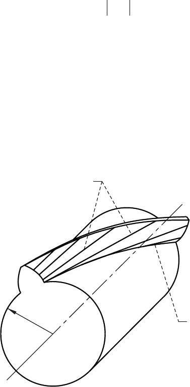
Profile Modification
The sensitivity of helical gears to misalignment has led designers and manufacturers to crown tooth surfaces.
The most common method of crowning is profile modification; that is, the profile of the cross section of one
of the mating gears (usually of the pinion) is deviated from the conventional involute profile. This can be
achieved as proposed in Litvin et al. (1995) by the application of two imaginary rack-cutters shown in
figure 2.3.5. The rack-cutters are rigidly connected and generate the pinion and the gear separately. Figure 2.3.5(a)
shows both rack-cutter profiles. The normal section of the pinion rack-cutter that generates the pinion space is
shown in figure 2.3.5(b), and the normal section of the gear rack-cutter that generates the gear tooth is shown
in figure 2.3.5(c). The deviation of the pinion rack-cutter profile from the gear rack-cutter profile is represented
by a parabolic function with the parabola coefficient a
c
. The tooth surfaces in the case of profile modification
are in point contact, and the path of contact is a helix, as shown in figure 2.3.6.
It can be easily verified that the profile modification enables one to localize the bearing contact and to avoid
an edge contact that might be caused by gear misalignment. However, the discussed modification does not allow
the elimination of transmission errors caused by misalignment, as shown in figure 2.3.7. Therefore, to reduce
the level of noise and vibration, it is necessary to provide a predesigned parabolic function of transmission errors
in addition to profile modifications.
2.4 Development of Face-Gear Drives
Introduction
Face-gear drives have found application in the transformation of rotation between intersected and crossed
axes. The Fellows Corporation invented the method of manufacturing face gears by a shaper which is based on
simulating the meshing of the generating shaper with the face gear by cutting.
Face-gear drives was the subject of intensive research presented in Davidov (1950) and Litvin (1968, 1994).
New developments in this area were supported by NASA Lewis Research Center and McDonnell Douglas
Helicopter Systems. An important application of face-gear drives in helicopter transmissions is based on the
concept of torque split (fig. 2.4.1). There are other examples of the successful application of face-gear drives
in transmissions.
Pinion rotation, f
1
, deg
Transmission error, Df
2
, arc sec
Figure 2.3.7.—Function of transmission errors for modified
involute helical gear drive when Dg
= 3 arc min.
–25
–20
–15
–10
10
5
0
–5
15
20
–5 5 15 20
–10–15–20 0 10
60 NASA RP–1406
Pitch Surfaces
The pitch surfaces for bevel gears are two cones (fig. 2.4.2(a)) with pitch angles
γ
1
and
γ
2
. The line of tangency
OI of the pitch cones is the instantaneous axis of rotation. The cones roll over each other in relative motion that
can be represented as rotation about OI. The pitch surfaces in a face-gear drive are the pinion pitch cylinder of
radius r
p1
and the face-gear pitch cone with the pitch angle
γ
(fig. 2.4.2(b)). The tooth element proportions in
bevel gears are related by the application of the pitch line OI (fig. 2.4.2(a)) as the middle line of the teeth. The
tooth height in face-gear drives is constant, and the middle line of the teeth is the line of tangency O'M of the
pinion pitch cylinder of radius r
p1
and the gear pitch cone with apex angle
γ
. It will be shown in the next section
that since O'M does not coincide with the instantaneous axis OI, the face-gear teeth become sensitive to
undercutting and pointing.
Generation of Face Gears
The process of generation by a shaper is shown in figure 2.4.3. Grinding and hobbing by a worm is a recently
developed process for face-gear generation. Methods for determining the surface of the worm (fig. 2.4.4) and
its dressing were developed by researchers at the University of Illinois at Chicago and at McDonnell Douglas
Helicopter Systems.
Avoidance of Undercutting and Pointing
The tooth of a face gear in three-dimensional space is shown in figure 2.4.5. The fillet surface is generated
by the top edge of the shaper tooth. Line L* is the line of tangency of the working part of the tooth surface and
the fillet. Undercutting may occur in plane A and pointing in plane B. The tooth surface is covered by lines of
tangency L of the face gear with the generating shaper.
The tooth of a face gear may be undercut and pointed in the process of generation by a shaper. These defects
can be avoided by properly designing the tooth length of the face gear. Dimensions L
1
and L
2
determine the zone
that is free of undercutting and pointing. The equations for computing L
1
and L
2
are represented in Litvin (1994).
The length of teeth (L
1
− L
2
) with respect to the diametral pitch P
d
may be represented by the unitless coefficient
Engine input
Driving spur pinion
Face-gears
Combining
gear
Rotor shaft output
NOTAR
TM
output
Sun gear
Figure 2.4.1.—Application of face-gear drives in helicopter transmissions.
NASA RP–1406 61
Figure 2.4.3.—Generation of face gear by shaper.
2 (face gear)
z
2
y
m
z
m
, z
s
O
2
, O
s
, O
m
v
(2)
v
(s)
g
m
s (shaper)
Figure 2.4.2.—Pitch surfaces of bevel gears and gears of face drive. (a) Bevel gears. (b) Face gears.
(a)
b
g
a
I
2
1
O
g
2
g
1
v
(1)
v
(2)
g
m
= 180° – g
(b)
g
a
b
P
M
I
O
O'
g
1
2r
p1
Figure 2.4.4.—Grinding worm for face gears.
62 NASA RP–1406
cLLP
d
=−
()
21
whose value depends on the gear ratio m
l2
= N
2
/N
1
of the face gear. It is recommend that m
12
> 4 be used to obtain
c > 10.
Localization of Bearing Contact
When the number of shaper teeth equals the number of pinion teeth, misalignment may cause the separation
of the face-gear teeth and the pinion and then the loss of their edge contact. To avoid this defect, it becomes
necessary to localize the bearing contact between the pinion and the face gear. This localization can be achieved
by applying a shaper with the tooth number N
s
> N
p
so that N
s
− N
p
= 1−3, where N
p
is the pinion tooth number.
Another approach is based on varying the tool plunging (grinding disk or cutter) in the pinion generation process
(see section 2.2). In such an approach, N
s
= N
p
.
Contact
lines L
B
A
Fillet
surface
Figure 2.4.5.—Tooth of face gear in three-dimensional
space.
L*