Menon E.S. Liquid Pipeline Hydraulics
Подождите немного. Документ загружается.

Pressure Drop due to Friction 53
Finally, the pressure drop due to friction is calculated using the
equation
P
m
=0.241(f SgQ
2
)/D
5
(3.43)
where
P
m
=Frictional pressure drop, psi/mile
f=Friction factor, dimensionless
Sg=Liquid specific gravity
Q=Flow rate, bbl/day
D=Pipe internal diameter, in.
In SI units the MIT equation is expressed as follows:
P
m
=6.2191×10
10
(f SgQ
2
)/D
5
(3.44)
where
P
m
=Frictional pressure drop, kPa/km
f=Friction factor, dimensionless
Sg=Liquid specific gravity
Q=Flow rate, m
3
/hr
D=Pipe internal diameter, mm
Comparing Equation (3.43) with Equations (3.27) and (3.28) and
recognizing the relationship between transmission factor F and Darcy
friction factor f, using Equation (3.29) it is evident that the friction factor f
in Equation (3.43) is not the same as the Darcy friction factor. It appears to
be one-fourth the Darcy friction factor.
Example Problem 3.6
A steel pipeline of 500 mm outside diameter, 10 mm wall thickness is used
to transport heavy crude oil at a flow rate of 800 m3/hr at 100°C. Using the
MIT equation calculate the friction loss per kilometer of pipe assuming an
internal pipe roughness of 0.05 mm. The heavy crude oil has a specific
gravity of 0.89 at 100°C and a viscosity of 120 cSt at 100°C.
Solution
From Equation (3.18)
Reynolds number=353,678×800/(120×480)=4912
The flow is therefore turbulent.
Modified Reynolds number=4912/7742=0.6345
Friction factor=0.0018+0.00662(1/0.6345)
0.355
=0.0074
Copyright © 2004 by Marcel Dekker, Inc.
Chapter 354
Pressure drop from Equation (3.44) is
P
m
=6.2191×10
10
(0.0074×0.89×800×800)/480
5
=10.29 kPa/km
3.10 Miller Equation
The Miller equation, also known as the Benjamin Miller formula, is used
in hydraulics studies involving crude oil pipelines. This equation does not
consider pipe roughness and is an empirical formula for calculating the
flow rate from a given pressure drop. The equation can also be rearranged
to calculate the pressure drop from a given flow rate. One of the popular
versions of this equation is as follows:
Q=4.06(M)(D
5
P
m
/Sg)
0.5
(3.45)
where M is defined as follows:
M=Log
10
(D
3
SgP
m
/cp
2
)+4.35 (3.46)
and
Q=Flow rate, bbl/day
D=Pipe internal diameter, in.
P
m
=Frictional pressure drop, psi/mile
Sg=Liquid specific gravity
cp=Liquid viscosity, centipoise
In SI units, the Miller equation is as follows:
Q=3.996×10
-6
(M)(D
5
P
m
/Sg)
0.5
(3.47)
where M is defined as follows:
M=Log
10
(D
3
SgP
m
/cp
2
)-0.4965 (3.48)
where
Q=Flow rate, m
3
/hr
D=Pipe internal diameter, mm
P
m
=Frictional pressure drop, kPa/km
Sg=Liquid specific gravity
cp=Liquid viscosity, centipoise
It can be seen from the above version of the Miller equation that
calculating the pressure drop P
m
from the flow rate Q is not
straightforward. This is because the parameter M depends on the pressure
drop P
m
. Therefore, if we solve for P
m
in terms of Q and other parameters
Copyright © 2004 by Marcel Dekker, Inc.
Pressure Drop due to Friction 55
from Equation (3.45), we get
P
m
=(Q/4.06M)
2
(Sg/D
5
) (3.49)
where M is calculated from Equation (3.46).
To calculate P
m
from a given value of flow rate Q, we use a trial-and-
error approach. First, we assume a value of P
m
to get a starting value of M
from Equation (3.46). This value of M is then substituted in Equation
(3.49) to determine a second approximation for P
m
. This value of P
m
will be
used to generate a better value of M from Equation (3.46) which is then
used to recalculate P
m
. Once the successive values of P
m
are within an
allowable tolerance, such as 0.01 psi/mile, the iteration can be terminated
and the value of pressure drop P
m
has been calculated.
Example Problem 3.7
Using the Miller equation determine the pressure drop in a 14 in. diameter,
0.250 in. wall thickness, crude oil pipeline at a flow rate of 3000 gal/min.
The crude oil specific gravity is 0.825 at 60°F and the viscosity is 15 cSt at
60°F.
Solution
Liquid viscosity in centipoise=0.825×15=12.375 cP
First the parameter M is calculated from Equation (3.46) using an initial
value of P
m
=10.0:
M=Log
10
(13.5
3
×0.825×10.0/12.375
2
)+4.35
=6.4724
Using this value of M in Equation (3.49), we get
P
m
=[3000×34.2857/(4.06×6.4724)]
2
(0.825/13.5
5
)
=28.19 psi/mile
We were quite far off in our initial estimate of P
m
.
Using this value of P
m
, a new value of M is calculated as
M=6.9225
Substituting this value of M in Equation (3.49), we get
P
m
=24.64
By successive iteration, we get a final value for P
m
of 25.02 psi/mile.
Copyright © 2004 by Marcel Dekker, Inc.
Chapter 356
3.11 T.R.Aude Equation
Another pressure drop equation used in the pipeline industry that is
popular among companies that transport refined petroleum products is the
T.R.Aude equation, sometimes referred to simply as the Aude equation.
This equation is named after the engineer who conducted experiments on
pipelines in the 1950s.
The Aude equation is used in pressure drop calculations for 8 in. to 12
in. pipelines. This method requires the use of the Aude K-factor,
representing pipeline efficiency. One version of this formula is given
below:
P
m
=[Q(z
0.104
)(Sg
0.448
)/(0.871(K)(D
2.656
))]
1.812
(3.50)
where
P
m
=Pressure drop due to friction, psi/mile
Q=Flow rate, bbl/hr
D=Pipe internal diameter, in.
Sg=Liquid specific gravity
z=Liquid viscosity, centipoise
K=T.R.Aude K-factor, usually 0.90 to 0.95
In SI units the Aude equation is as follows:
P
m
=8.888×10
8
[Q(z
0.104
)(Sg
0.448
)/(K(D
2.656
))]
1.812
(3.51)
where
P
m
=Frictional pressure drop, kPa/km
Sg=Liquid specific gravity
Q=Flow rate, m
3
/hr
D=Pipe internal diameter, mm
z=Liquid viscosity, centipoise
K=T.R.Aude K-factor, usually 0.90 to 0.95
Since the Aude equation for pressure drop given above does not contain
pipe roughness, it can be deduced that the K-factor somehow must take
into account the internal condition of the pipe. As with the Hazen-Williams
C-factor discussed earlier, the Aude K-factor is also an experience-based
factor and must be determined by field measurement and calibration of an
existing pipeline. If field data is not available, engineers usually
approximate using a value such as K=0.90 to 0.95. A higher value of K
will a result in a lower pressure drop for a given flow rate or a higher a flow
rate for a given pressure drop.
It must be noted that the Aude equation is based on field data collected
from 6 in. and 8 in. refined products pipelines. Therefore, caution must be
used when applying this formula to larger pipelines.
Copyright © 2004 by Marcel Dekker, Inc.
Pressure Drop due to Friction 57
3.12 Minor Losses
In most long-distance pipelines, such as trunk lines, the pressure drop due
to friction in the straight lengths of pipe forms the significant proportion of
the total frictional pressure drop. Valves and fittings contribute very little to
the total pressure drop in the entire pipeline. Hence, in such cases, pressure
losses through valves, fittings, and other restrictions are generally
classified as “minor losses”. Minor losses include energy losses resulting
from rapid changes in the direction or magnitude of liquid velocity in the
pipeline. Thus pipe enlargements, contractions, bends, and restrictions
such as check valves and gate valves are included in minor losses.
In short pipelines, such as terminal and plant piping, the pressure loss
due to valves, fittings, etc., may be a substantial portion of the total
pressure drop. In such cases, the term “minor losses” is a misnomer.
Therefore, in long pipelines the pressure losses through bends, elbows,
valves, fittings, etc., are classified as “minor” and in most instances may be
neglected without significant error. However, in shorter pipelines these
losses must be included for correct engineering calculations. Experiments
with water at high Reynolds numbers have shown that the minor losses
vary approximately as the square of the velocity. This leads to the
conclusion that minor losses can be represented by a function of the liquid
velocity head or kinetic energy (V
2
/2g).
Accordingly, the pressure drop through valves and fittings is generally
expressed in terms of the liquid kinetic energy V
2
/2g multiplied by a head
loss coefficient K. Comparing this with the Darcy-Weisbach equation for
head loss in a pipe, we can see the following analogy. For a straight pipe,
the head loss h is V
2
/2g multiplied by the factor (fL/D). Thus, the head loss
coefficient for a straight pipe is fL/D.
Therefore, the pressure drop in a valve or fitting is calculated as
follows:
h=KV
2
/2g (3.52)
where
h=Head loss due to valve or fitting, ft
K=Head loss coefficient for the valve or fitting, dimensionless
V=Velocity of liquid through valve or fitting, ft/s
g=Acceleration due to gravity, 32.2 ft/s
2
in English units
The head loss coefficient K is, for a given flow geometry, considered
practically constant at high Reynolds number. K increases with pipe
roughness and with lower Reynolds numbers. In general the value of K is
determined mainly by the flow geometry or by the shape of the pressure
loss device.
Copyright © 2004 by Marcel Dekker, Inc.
Chapter 358
It can be seen from Equation (3.52) that K is analogous to the term (fL/
D) for a straight length of pipe. Values of K are available for various types
of valves and fittings in standard handbooks, such as the Crane Handbook
Flow of Fluids through Valves, Fittings, and Pipes and Cameron Hydraulic
Data. A table of K-factor values commonly used for valves and fittings is
included in Appendix A, Table A.9.
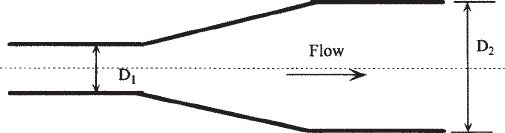
3.12.1 Gradual Enlargement
Consider liquid flowing through a pipe of diameter D
1
. If at a certain point
the diameter enlarges to D
2
, the energy loss that occurs due to the
enlargement can be calculated as follows:
h=K(V
1
-V
2
)
2
/2g (3.53)
where V
1
and V
2
are the velocity of the liquid in the smaller-diameter and
the larger-diameter pipe respectively. The value of K depends upon the
diameter ratio D
1
/D
2
and the different cone angle due to the enlargement. A
gradual enlargement is shown in Figure 3.5.
For a sudden enlargement K=1.0 and the corresponding head loss is
h=(V
1
-V
2
)
2
/2g (3.54)
Example Problem 3.8
Calculate the head loss due to a gradual enlargement in a pipe that flows
100 gal/min of water from a 2 in. diameter to a 3 in. diameter with an
included angle of 30°. Both pipe sizes are internal diameters.
Solution
The liquid velocities in the two pipe sizes are as follows:
V
1
=0.4085×100/2
2
=10.21 ft/s
V
2
=0.4085×100/3
2
=4.54 ft/s
Diameter ratio=3/2=1.5
Figure 3.5 Gradual enlargement.
Copyright © 2004 by Marcel Dekker, Inc.

Pressure Drop due to Friction 59
From charts, for diameter ratio=1.5 and cone angle=30° the value of K is
K=0.38
Therefore head loss due to gradual enlargement is
h=0.38×(10.21-4.54)
2
/64.4=0.19 ft
If the expansion were a sudden enlargement from 2 in. to 3 in., the head
loss would be
h=(10.21-4.54)
2
/64.4=0.50 ft
3.12.2 Abrupt Contraction
For flow through an abrupt contraction, the flow from the larger pipe
(diameter D
1
and velocity V
1
) to a smaller pipe (diameter D
2
and velocity
V
2
) results in the formation of a vena contracta or throat, immediately after
the diameter change. At the vena contracta, the flow area reduces to A
c
with increased velocity of V
c
. Subsequently the flow velocity decreases to
V
2
in the smaller pipe. Thus from velocity V
1
, the liquid first accelerates to
velocity V
c
at the vena contracta and subsequently decelerates to V
2
. This is
shown in Figure 3.6.
The energy loss due to the sudden contraction depends upon the ratio of
the pipe diameters D
2
and D
1
and the ratio A
c
/A
2
. The value of the head loss
coefficient K can be found using Table 3.1, where C
c
=A
c
/A
2
. The ratio A
2
/
A
1
can be calculated from the ratio of the diameters D
2
/D
1
.
A pipe connected to a large storage tank represents a type of abrupt
contraction. If the storage tank is a large body of liquid, we can state that
this is a limiting case of the abrupt contraction. For such a square-edged
pipe entrance from a large tank A
2
/A
1
=0. From Table 3.1, for this case
K=0.5 for turbulent flow.
Figure 3.6 Abrupt contraction.
Copyright © 2004 by Marcel Dekker, Inc.

Chapter 360
Another type of pipe entrance from a large tank is called a re-entrant
pipe entrance. If the pipe is thin-walled and the opening within the tank is
located more than one pipe diameter upstream from the tank wall, the K
value will be close to 0.8.
If the edges of the pipe entrance in a tank are rounded or bell-shaped,
the head loss coefficient is considerably smaller. An approximate value for
K for a bell-mouth entrance is 0.1.
3.12.3 Head Loss and L/D Ratio for Pipes and Fittings
We have discussed how minor losses can be accounted for using the head
loss coefficient K in conjunction with the liquid velocity head. Table A.9 in
Appendix A lists K values for common valves and fittings.
Referring to the Table A.9 for K values, we see that for a 16 in. gate
valve, K=0.10. Therefore, compared with a 16 in. straight pipe, we can
write, from the Darcy-Weisbach equation:
or
If we assume f=0.0125, we get
Table 3.1 Head Loss Coefficient K for
Abrupt Contraction
Copyright © 2004 by Marcel Dekker, Inc.
Pressure Drop due to Friction 61
This means that compared with a straight pipe 16 in. in diameter, a 16 in.
gate valve has an L/D ratio of 8, which causes the same friction loss. The
L/D ratio represents the equivalent length of straight pipe in terms of its
diameter that will equal the pressure loss in the valve or fitting. In Table
A.10 in Appendix A the L/D ratios for various valves and fittings are given.
Using the L/D ratio we can replace a 16 in. gate valve with 8×16 in.=
128 in. of straight 16 in. pipe. This length of pipe will have the same
friction loss as the 16 in. gate valve. Thus we can use the K values or L/D
ratios to calculate the friction loss in valves and fittings.
3.13 Internally Coated Pipes and Drag Reduction
In turbulent flow, pressure drop due to friction depends on the pipe
roughness. Therefore, if the internal pipe surface can be made smoother,
the frictional pressure drop can be reduced. Internally coating a pipeline
with an epoxy coating will considerably reduce the pipe roughness
compared with uncoated pipe.
For example, if the uncoated pipe has an absolute roughness of 0.002
in., coating the pipe can reduce roughness to a value as low as 0.0002 in.
The friction factor f may therefore reduce from 0.02 to 0.01 depending on
the flow rate, Reynolds number, etc. Since pressure drop is directly
proportional to the friction factor in accordance with the Darcy-Weisbach
equation, the total pressure drop in the internally coated pipeline in this
example would be 50% of that in the uncoated pipeline.
Another method of reducing frictional pressure drop in a pipeline is by
using drag reduction. Drag reduction is the process of reducing the
pressure drop due to friction in a pipeline by continuously injecting a very
small quantity (parts per million, or ppm) of a high-molecular-weight
hydrocarbon, called the drag reduction agent (DRA), into the flowing
liquid stream. The DRA is effective only in pipe segments between two
pump stations. It degrades in performance as it flows through the pipeline
for long distances. It also completely breaks up or suffers shear
degradation as it passes through pump stations, meters and other
restrictions. DRA works only in turbulent flow and with low-viscosity
liquids. Thus, it works well with refined petroleum products (gasoline,
diesel, etc.) and light crude oils. It is ineffective in heavy crude oil
pipelines, particularly in laminar flow. Currently, the two leading vendors
of DRA products in the United States are Baker Petrolite and Conoco-
Phillips.
To determine the amount of drag reduction using DRA we proceed as
follows. If the pressure drops due to friction with and without DRA are
known, we can calculate the percentage drag reduction:
Copyright © 2004 by Marcel Dekker, Inc.
Chapter 362
Percentage drag reduction=100(DP
0
-DP
1
)/DP
0
(3.55)
where
DP
0
=Friction drop in pipe segment without DRA, psi
DP
1
=Friction drop in pipe segment with DRA, psi
The above pressure drops are also referred to as untreated versus treated
pressure drops. It is fairly easy to calculate the value of untreated pressure
drop, using the pipe size, liquid properties, etc. The pressure drop with
DRA is obtained using DRA vendor information. In most cases involving
DRA, we are interested in calculating how much DRA we need to use to
reduce the pipeline friction drop, and hence the pumping horsepower
required. It must be noted that DRA may not be effective at the higher flow
rate, if existing pump and driver limitations preclude operating at higher
flow rates due to pump driver horsepower limitation.
Consider a situation where a pipeline is limited in throughput due to
maximum allowable operating pressures (MAOP). Let us assume the
friction drop in this MAOP limited pipeline is 800 psi at 100,000 bbl/day.
We are interested in increasing pipeline flow rate to 120,000 bbl/day using
DRA and we would proceed as follows:
Flow improvement desired=(120,000-100,000)/100,000=20%
If we calculate the actual pressure drop in the pipeline at the increased flow
rate of 120,000 bbl/day (ignoring the MAOP violation) and assume that we
get the following pressure drop:
Frictional pressure drop at 120,000 bbl/day=1150 psi
and
Frictional pressure drop at 100,000 bbl/day=800 psi
The percentage drag reduction is then calculated from Equation (3.55) as
Percentage drag reduction=100(1150-800)/1150=30.43%
In the above calculation we have tried to maintain the same frictional drop
(800 psi) using DRA at the higher flow rate as the initial pressure-limited
case. Knowing the percentage drag reduction required, we can get the
DRA vendor to tell us how much DRA will be required to achieve the
30.43% drag reduction, at the flow rate of 120,000 bbl/day. If the answer is
15 ppm of Brand X DRA, we can calculate the daily DRA requirement as
follows:
Quantity of DRA required=(15/10
6
)(120,000)(42)=75.6 gal/day
Copyright © 2004 by Marcel Dekker, Inc.