Middleton W.M. (ed.) Reference Data for Engineers: Radio, Electronics, Computer and Communications
Подождите немного. Документ загружается.

28-2
INTRODUCTION
During the last twenty-five years, there has been
rapid advancement in the theory and application of dig-
ital signal processing (DSP) in various engineering dis-
ciplines. Interest has grown in digital signal processing
because, not only has the general-purpose computer
become more readily available, but digital integrated
circuits have become more highly integrated and
cheaper, a trend that will continue into the foreseeable
future. Very large scale integration (VLSI) techniques
have produced high-density read-only memories
(ROM)
and microprocessors that provide enormous
flexibilities in the design of digital hardware systems.
Digital filters offer distinct advantages over analog
(continuous-time) filters in many applications, although
they are not good substitutes for
all
analog filters. The
major advantages are good numerical accuracy, pro-
grammability, stability in the presence of changing envi-
ronmental conditions, suitability for multiplexing, and
convenience for processing data that is directly available
in binary form. Some of the disadvantages of these fil-
ters are the relatively high per-unit costs for high-fre-
quency applications, frequency limitations imposed by
the speed of the digital hardware, and the necessity for a
significant amount of clocking and control circuitry to
sequence the binary operations properly.
The
design
of a digital filter involves determining
either a set of time-domain difference equations or a
z-
domain digital transfer function that satisfies given
specifications. A digital filter can be obtained by first
designing an analog prototype and then transforming it
into a discrete-time system by a sampled-data transfor-
mation. Another approach is to use a computer optimi-
zation to place the z-domain poles and zeros
so
the
discrete-time system will meet specifications directly.
The first approach takes advantage
of
well known ana-
log design techniques, while the second provides
greater flexibility because it does not depend on an
analog design step. Digital filter
implementation
involves choosing a network topology and hardware
modules for the final network. At this stage, the
designer must analyze the effects of quantization error,
because error performance and network topology are
closely related. Digital
hardware design
consists of
designing the individual circuit elements (adders, mul-
tipliers, shift registers, etc.).
If
the system is to be inte-
grated, it also includes the IC layouts.
In many applications, implementation is ultimately
accomplished in software on a general-purpose com-
puter. In these cases, the emphasis is
on
the design and
implementation stages, since hardware design and sys-
tem architecture
are
dictated by the general computer
system. However, with the rapid advances that are now
being made in the automated design and manufacture
of VLSI monolithic circuits, engineers enjoy the free-
dom to specify custom designed digital functions and
have them quickly fabricated in low-cost silicon
devices. This new capability will result in digital signal
processing becoming less dependent on the general
computer. New techniques for improving data rates,
reducing circuit complexity, and improving reliability
will become increasingly important as more custom-
designed
VLSI
digital systems come into common
usage.
Several sampled-data analog technologies exist
which implement discrete-time filters. While lacking
the flexibility of all-digital implementations, these
technologies, which include switched-capacitor fil-
ters, surface-acoustic-wave filters, and acoustic-
charge-transport devices, often represent the most
cost-effective method of filtering in certain perfor-
mance regimes.
FUNDAMENTALS FOR
DISCRETE-TIME SYSTEMS
Basic
Definitions
A
continuous-time
(CT) signal is a function,
s(t),
that is defined for all time
t
contained in some interval
on the real line. For historical reasons, CT signals are
often called
analog signals.
If the domain of definition
for
s(t)
is restricted to a set of discrete points
t,
=
nT,
where
n
is an integer and
T
is the sampling period, the
signal
s(t,)
is called a
discrete-time
(DT) signal. Often,
if the sampling interval is well understood within the
context of the discussion, the sampling period is nor-
malized by
T
=
1,
and a DT signal is represented sim-
ply as a sequence
s(n).
If the values of the sequence
s(n)
are
to be represented with a finite number
of
bits
(as required in a finite state machine), then
s(n)
can
take on only a discrete set of values. In this case,
s(n)
is called a
digital signal.
Much of the theory that
is
used in DSP is actually the theory of DT signals and
DT systems, in that no amplitude quantization
is
assumed in the mathematics. However, all signals pro-
cessed in binary machines are truly digital signals.
One important question that arises in virtually every
application is the question of how many bits are
required in the representation of the digital signals
to
guarantee that the performance of the digital system is
acceptably close to the performance of the ideal DT
system.
Linear CT systems are characterized by the familiar
mathematics of differential equations, continuous con-
volution operators, Laplace transforms, and Fourier
transforms. Similarly, linear
DT
systems are described
by the mathematics of difference equations, discrete
convolution operators, Z-transforms, and discrete
Fou-
rier transforms. It appears that for every major concept
in CT systems, there is a similar concept for
DT
sys-
tems (e.g., differential equations and difference equa-
tions, continuous convolution and discrete
convolution, etc.). However, in spite of this duality of
concepts, it is impossible to apply directly the mathe-
matics of CT systems to DT systems, or vice versa.
Many modern systems consist
of
both analog and
digital subsystems, with appropriate analog-to-digital
(AD) and digital-to-analog (D/A) devices at the inter-
DISCRETE-TIME SIGNAL PROCESSING
28-3
faces. For example, it is common to use a digital com-
puter in the control loop of an analog plant. Analytical
difficulties often occur at the boundaries between the
analog and digital portions of the system because the
mathematics used on
the
two sides of the interface
must be different. It is often useful to assume that a
sequence
s(n)
is derived from an analog signal
s,(t)
by
ideal sampling, Le.
An alternative model for the sampled signal is denoted
by
s*(t)
and defined by
n=--m
where
S,(t)
is an analog impulse function. Both
s(n)
and
s*(t)
are used throughout the literature to represent
an ideal sampled signal. Note that even though
s(n)
and s*(t) represent the same essential information,
s(n)
is
a DT signal and
s*(t)
is a CT signal. Hence, they are
not mathematically identical.
In
fact,
s(n)
is a “DT-
world” model of a sampled signal, whereas
s*(t)
is a
“CT-world” model of the same phenomenon.
Finite Convolution and
Difference Equations
Let y(n)
=
F{x(n)} define the input-output relation
for a discrete-time system with input x(n) and output
y(n). The following definitions are commonly used to
define the properties of linearity, shift invariance, cau-
sality, and stability:
Linearity-F is linear if and only if
F
{
axl@)
+
bx,(n)}
=aF
{xl(n)}+bF {x,(n)},whereaandb
are scalar constants andxl(n) and xz(n) are two
arbitrary input sequences.
Shift-Invariance-
F
is shift-invariant if and
only
if
y(n
-no)
=
F
{x(n
-
no)}
for all integer values of
no.
Causality
-
F
is causal if and only if y(n) depends
on
samples of
x(k)
at times
k
5
n.
Stability
(BIB0)-
F
is stable in the bounded-input
bounded-output (BIBO) sense if and only if y(n)
remains bounded for all x(n) that are bounded.
Whenever
F
is linear and shift-invariant, it is possi-
ble to express the zero state response, y(n), due to an
arbitrary
input,
x(n),
in
terms
of
a
discrete convolution
of
h(n)
and x(n), where
h(n)
=
F
{
S(n)},
and
S(n)
=
0
for n
#
0
and
S(n)
= 1
when
n
=
1.
The function
S(n)
is
called a unit pulse,
h(n)
is the unit-pulse response* of
F, and the finite convolution is expressed by
y(n)= Ch(k)x(n-k) (Eq.
3)
*
The term “impulse response” is
often
used interchange-
ably
with the
term
“unit
pulse response.”
If
F
is
causal, h(k)
=
0
for
k
e
0,
and the lower limit on
the summation in Eq.
3
becomes zero.
In
certain types of DT systems, the unit-pulse
response is zero outside of a finite interval containing
N
samples; Le.,
h(n)
=
0
for
n
<
0
and
n
2
N.
This type
of system is a finite impulse response (FIR) DT sys-
tem.
If
h(n)
is supported over an infinite length inter-
val, then
F
is called an infinite impulse response
(IIR)
DT system. These two classes constitute
the
two
important types of digital filters, with each class hav-
ing distinct advantages and disadvantages with regard
to stability, quantization error performance, and com-
putational efficiency.
An IIR system has an infinite memory because, in
general, the output depends on the input all the way
into the infinite past. Such
a
system can also be charac-
terized by
an
Nth order linear difference equation, as
given by
y(n)
+
aly(n
-
1)
+
. .
.
+
y(n
-
N
+
1)
=
bo
x(n)
+
. . .
+
bM-l x(n
-M
+
1)
(Eq.
4)
A linear difference equation is a recursive relation that
can be realized quite easily with digital multipliers,
adders, and unit delay registers. Hence, in some of the
older literature, IIRs
are
referred to as recursive filters.
Similarly, FIRS were often referred to as nonrecursive
(or transversal) filters. However, the terms recursive
and nonrecursive refer more specifically
to
the imple-
mentation of the filter, rather than the mathematical
structure. This fact is illustrated by
the
frequency sam-
pling structure,? which is a recursive realization of a
FIR system. The terms IIR and FIR are used in the
modem literature to eliminate any ambiguity that was
caused by the older terminology.
In
general, IIR systems
are
cheaper to implement
than FIR systems because the iteration of a difference
equation requires fewer arithmetic operations per out-
put sample, as compared to calculating a finite convo-
lution. However, IIR systems have “poles,” whereas
FIR systems do not. This implies that IIR systems
must be carefully designed to ensure stability. Also,
IIR systems suffer from limit cycle oscillations and
quantization error accumulation because quantization
efforts are recycled through the inherent feedback in
the recursion.
The Z-Transform
The Z-transform occupies the same position
of
importance in DT system theory as the Laplace trans-
form does in CT system theory. They
are
very similar
transforms that share many common properties.
How-
ever, it is important to emphasize that they cannot be
used interchangeably because they apply to different
types of systems.
-i-
Reference
25.
28-4
REFERENCE
DATA
FOR ENGINEERS
The 2-sided Z-transform of a DT signal,
s(n),
is
defined by
S(z)
=
s{s(n)}
=
Cs(n)z-"
(Eq.
5)
n=-m
where
S(z)
is said to exist for all
z&
such that the infi-
nite summation converges. Symbol
R
represents the
region of convergence
(R.O.C.)
of
S(z).
If the summa-
tion is taken from
n
=
0,
rather than
n
=
--w
the result is
called the 1-sided Z-transform. It is clear that for all
s(n)
such that
s(n)
3
0
for
n
<
0,
the 1-sided and 2-
sided Z-transforms are equivalent.
The inverse Z-transform is defined by
where
C
is a closed contour that encircles the origin
and lies entirely within the region of convergence for
S(z).
Eq.
6
is valid for both positive and negative val-
ues of
n.
In many applications, the inverse 2-transform
can be found from a table
of
Z-transform pairs, and
therefore it is seldom necessary to find the inverse Z-
transform from its definition. However, for cases
where it is desired to apply the definition of Eq.
6,
the
contour integral can be evaluated by means of the
well-known residue theorem.
(1/27rj)
fCS(z)
z"-'
dz
=
(residues of
S(z)z"-'
at the poles inside
C)
The normal technique for finding the residues of
S(z)
ziZ-l
is by the same method used in expanding
S(z)
z"+l
in a partid fraction expansion. It is important
to
note that the residue theorem is applicable only when
S(z)
zn-'
has singularities (poles) that occur at isolated
points in the z-plane. Fortunately, virtually all one-
dimensional DT systems and DT signals of practical
interest produce Z-transforms that are ratios of polyno-
mials in powers of
z.
The singular behavior of such
systems is characterized by poles and zeros, and hence
the residue theorem can be applied in virtually all
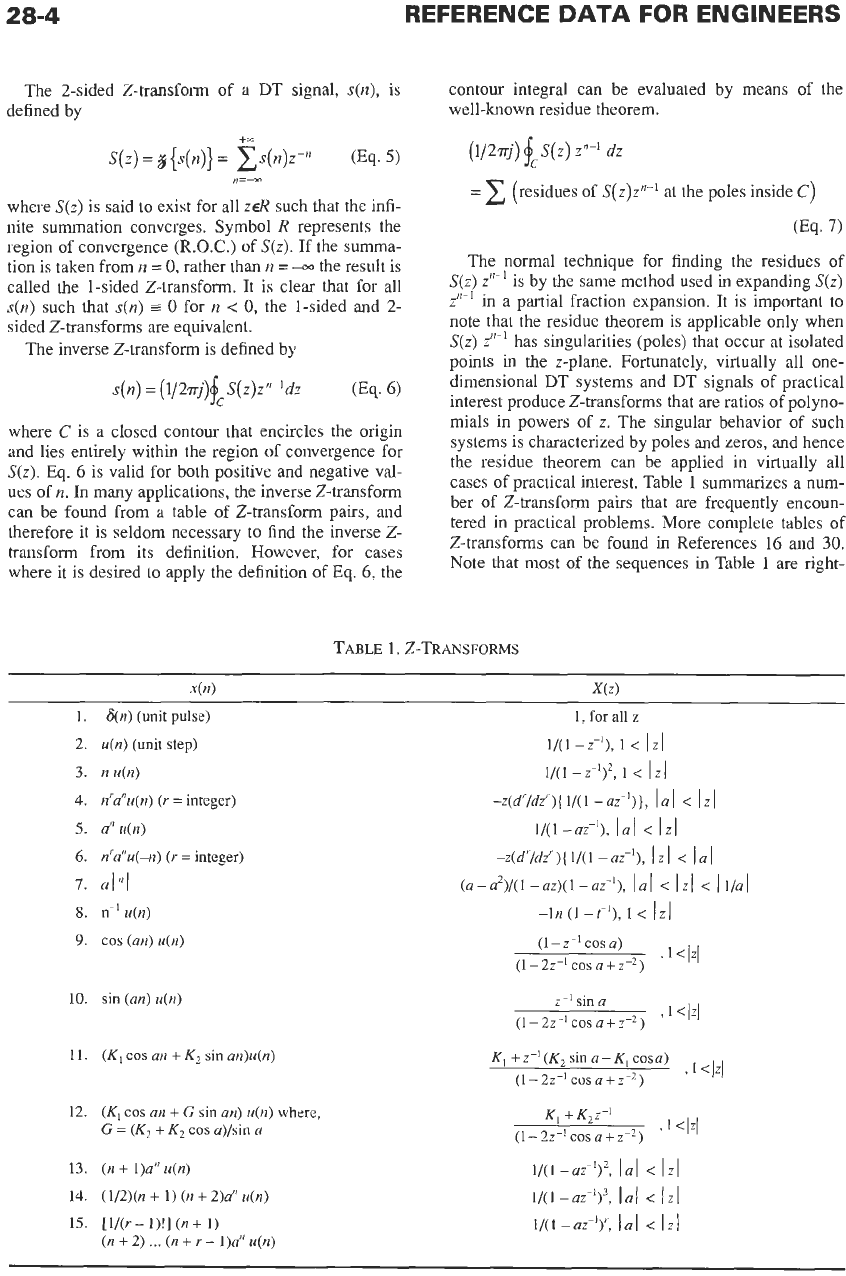
cases of practical interest. Table 1 summarizes a num-
ber of Z-transform pairs that are frequently encoun-
tered in practical problems. More complete tables of
2-transforms can be found in References
16
and
30.
Note that most of the sequences in Table 1
are
right-
TABLE
1.
2-TRANSFORMS
1.
2.
3.
4.
5.
6.
I.
8.
9.
10.
11.
12.
13.
14.
15.
~
x(n)
X(Z)
6(n)
(unit
pulse)
1,
for
all
z
u(n)
(unit
step)
n
u(n)
n'a"u(n)
(Y
=
integer)
an
u(n)
n'a"u(-n)
(r
=
integer)
alnl
n-'
u(n)
cos
(an)
u(n)
sin
(an)
u(n)
(K,
cos
an
+
K2
sin
an)u(n)
(K]
cos
an
+
G
sin
an)
u(n)
where,
G
=
(K,
+
K2 cos
a)/sin
a
(n
+
1)a"
u(n)
(1/2)(n
+
1)
(n
+
2)a"
u(n)
[l/(r
-
l)!]
(n
+
1)
(n
+
2)
...
(n
+
r-
1)a"
u(n)
K,
+
z-'
(K2
sin
a
-
K,
cosa)
I
1
<
IZI
(1
-
22-1 cos
a
+
z-2)
K,
+
K,z-'
,
1
<I%/
(1-22-'cos
a+z-2)
1/(1
-az-y,
I
al
<
I
ZI
1/(1 -az8)3,
la1
<
IZI
1/(1 -az-'):
la1
<
121
DISCRETE-TIME
SIGNAL PROCESSING
28-5
sided; i.e., x(n)
=
0
for
n
<
0.
The exceptions are entry
6,
which is left-sided, and entry
7,
which is two-sided.
For a given X(z), the corresponding
x(n)
may be right-
sided, left-sided, or two-sided, depending on the nature
of the region of convergence,
R.
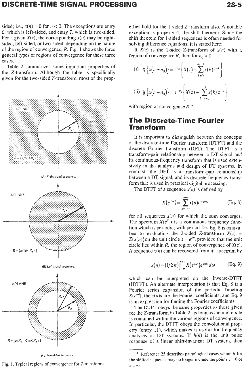
Fig.
1
shows the three
general types of regions of convergence for these three
cases.
Table
2
summarizes some important properties of
the
Z-transform. Although the table is specifically
given for the two-sided Z-transform, most of the prop-
$.
(A)
Right-sided
sequence.
(E)
Left-sided
sequence
t
erties hold for the 1-sided Z-transform also. A notable
exception
is
property
4,
the shift theorem. Since the
shift theorem for 1-sided sequences is often needed for
solving difference equations, it is stated here:
If X(z) is the 1-sided 2-transform of
x(n)
with a
region of convergence
R,
then for
no
>
0,
with region of convergence
R.*
The Discrete-Time Fourier
Transform
It
is
important to distinguish between the concepts
of the discrete-time Fourier transform (DTFT) and the
discrete Fourier transform (DFT). The DTFT is a
transform-pair relationship between a DT signal and
its continuous-frequency transform that is used exten-
sively in the analysis and design
of
DT systems.
In
contrast, the DFT is a transform-pair relationship
between a DT signal, and its discrete-frequency trans-
form that is used in practical digital processing.
The DTFT of a sequence
x(n)
is defined by
E=--
for all sequences
x(n)
for which the sum converges.
The spectrum
X(d")
is a continuous-frequency func-
tion which
is
periodic, with period 2r.
Eq.
8
is
equiva-
lent to evaluating the 2-sided Z-transform
X(z)
=
Z{x(n)}on the unit circle
z
=
d",
provided that the unit
circle lies within
R,
the region of convergence of X(z).
A sequence x(n) can be recovered from its spectrum by
which can be interpreted on the inverse-DTFT
(IDTFT).
An
alternate interpretation is that
Eq.
8
is a
Fourier series expansion of the periodic function
X(d"'), the
x(n)s
are the Fourier coefficients, and
Eq.
9
is an expression for finding the Fourier coefficients.
The DTFT obeys
the
same properties
as
those
given
for the Z-transform in Table 2, as long as the unit circle
is contained within the various regions of Convergence.
In
particular, the DTFT obeys
the
convolutional prop-
erty (entry ll), which makes it useful for frequency
analyses of DT systems.
If
h(n)
is
the unit pulse
response of a linear shift-invariant DT system, then
(C)
Two-sided
sequence.
Fig.
1.
Typical regions of convergence for
Z-transforms.
*
Reference
25
describes pathological cases
where
R
for
the shifted sequence may no longer include
the
points
z
=
0
or
Z=m.
28-6
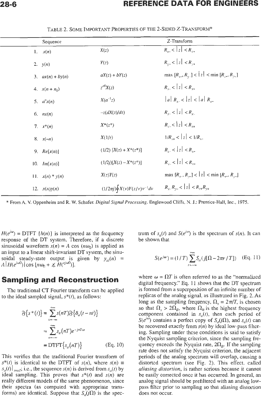
TABLE 2.
SOME
IMPORTANT
PROPERTIES
OF
THE
2-SIDED
Z-TRANSFORM*
Sequence Z-Transform
1.
x(n)
2.
y(n)
3.
ux(n)
+
by(n)
4.
x(n
+
no)
5.
a?@)
6.
nx(n)
7.
x*(n)
8.
x(-n)
9.
Re[x(n)]
10.
Zm[x(n)]
11.
x(n)
*
y(n)
12.
x(nlu(n)
*
From
A.
V.
Oppenheim and
R.
W.
Schafer.
Digital
Signal
Processing.
Englewood Cliffs,
N.
J.:
Prentice-Hall, Inc., 1975.
H(d")
=
DTFT
(h(n)}
is interpreted
as
the frequency
response of the DT system. Therefore, if
a
discrete
sinusoidal waveform
x(n)
=
A
cos
(nuo)
is applied
as
an input to
a
linear shift-invariant DT system, the sinu-
soidal steady-state output is given by
y,,(n)
=
A
I
H(d"O)
I
cos
[nwo
+
4
H('j"O)].
Sampling and Reconstruction
The traditional CT Fourier transform can be applied
to the ideal sampled signal,
s*(t),
as
follows:
s{s
*
(f)}
=
CS("')8{Zju('
-
"'I}
n=--
+-
=
c
s,
(nT)e-
PT"
=
DTFT{&T)}
(Eq.
10)
n=--
This
verifies that the traditional Fourier transform of
s*(t)
is identical to the DTFT of
s(n),
where
s(n)
=
s,(t)
I
pn5
i.e., the sequence
s(n)
is derived from
sa@)
by
ideal sampling. This proves that
s*(t)
and
s(n)
are
really different models
of
the same phenomenon, since
their spectra (as computed with appropriate trans-
forms)
are
identical. Suppose that
S,(jfL)
is
the spec-
trum of
s,(t)
and
S(do)
is the spectrum
of
s(").
It can
be shown that
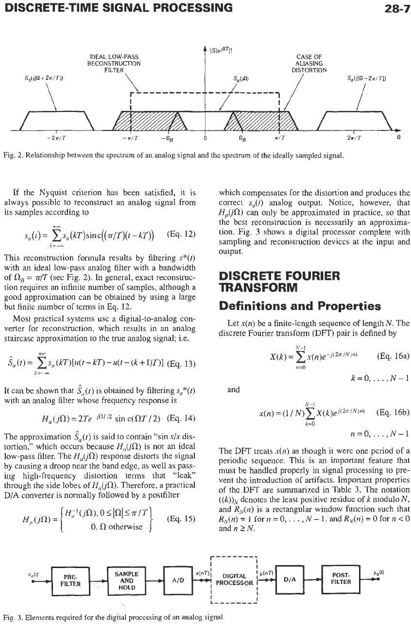
where
w
=
fLRT
is often referred to
as
the "normalized
digital frequency." Eq.
11
shows that the DT spectrum
is formed from
a
superposition of an infinite number of
replicas of the analog signal,
as
illustrated in Fig.
2.
As
long
as
the sampling frequency,
fls
=
2r/T, is
chosen
so
that
a,
>
2flE,
where
llB
is the highest frequency
component contained in
s,(t),
then each period of
S(e'")
contains
a
perfect copy
of
S,(jfL),
and
s,(t)
can
be recovered exactly from
s(n)
by ideal low-pass filter-
ing. Sampling under these conditions is said to satisfy
the Nyquist sampling criterion, since the sampling fre-
quency exceeds the Nyquist rate,
2fLE.
If the sampling
rate does not satisfy the Nyquist criterion, the adjacent
periods of the analog spectrum will overlap, causing
a
distorted specmm (see Fig.
2).
This effect, called
aliasing distortion,
is rather serious because it cannot
be easily corrected once it has occurred.
In
general,
an
analog signal should be prefiltered with an analog low-
pass filter prior
to
sampling
so
that aliasing distortion
does not occur.
DISCRETE-TIME SIGNAL PROCESSING
28-7
IDEAL
LOW-PASS
RECONSTRUCTION
0 n
-2r/T
-
a/T
-
nB
Fig.
2.
Relationship between the
spectrum
of
an
analog signal and
the
spectrum
of
the
ideally sampled signal.
If the Nyquist criterion has been satisfied, it is
always possible to reconstruct an analog signal from
its samples according to
+==
sU(t)
=
xs,(kT)sinc((.rr/T)(t-
kT))
(Eq. 12)
This reconstruction formula results by filtering s*(t)
with an ideal low-pass analog filter with a bandwidth
of
a,
=
r/T
(see Fig. 2).
In
general, exact reconstruc-
tion requires an infinite number of samples, although a
good approximation can be obtained by using a large
but finite number of terms in Eq. 12.
Most practical systems use
a
digital-to-analog con-
verter for reconstruction, which results in an analog
staircase approximation to the true analog signal; i.e.
k=--
+or
ia
(t)
=
(kT)[u(t
-
kT)
-
u(t
-
(k
+
1)T)I
(Eq. 13)
It
can be shown that
ia(t)
is obtained by filtering
s,*(t)
with an analog filter whose frequency response is
k=--
Ha
(ja)
=
2Te-jnT/' sin c(QT
/
2)
(Eq. 14)
The approximation
ia(t)
is said
to
contain "sinx/x dis-
tortion," which occurs because
HJjfl)
is not an ideal
low-pass filter. The
Hu(jfl)
response distorts the signal
by causing a droop near the band edge, as well as pass-
ing high-frequency distortion terms that "leak"
through the side lobes of
HJja).
Therefore, a practical
D/A converter is normally followed by a postfilter
which compensates for the distortion and produces the
correct
sa(t)
analog output. Notice, however, that
HJjfI)
can only be approximated in practice,
so
that
the best reconstruction is necessarily an approxima-
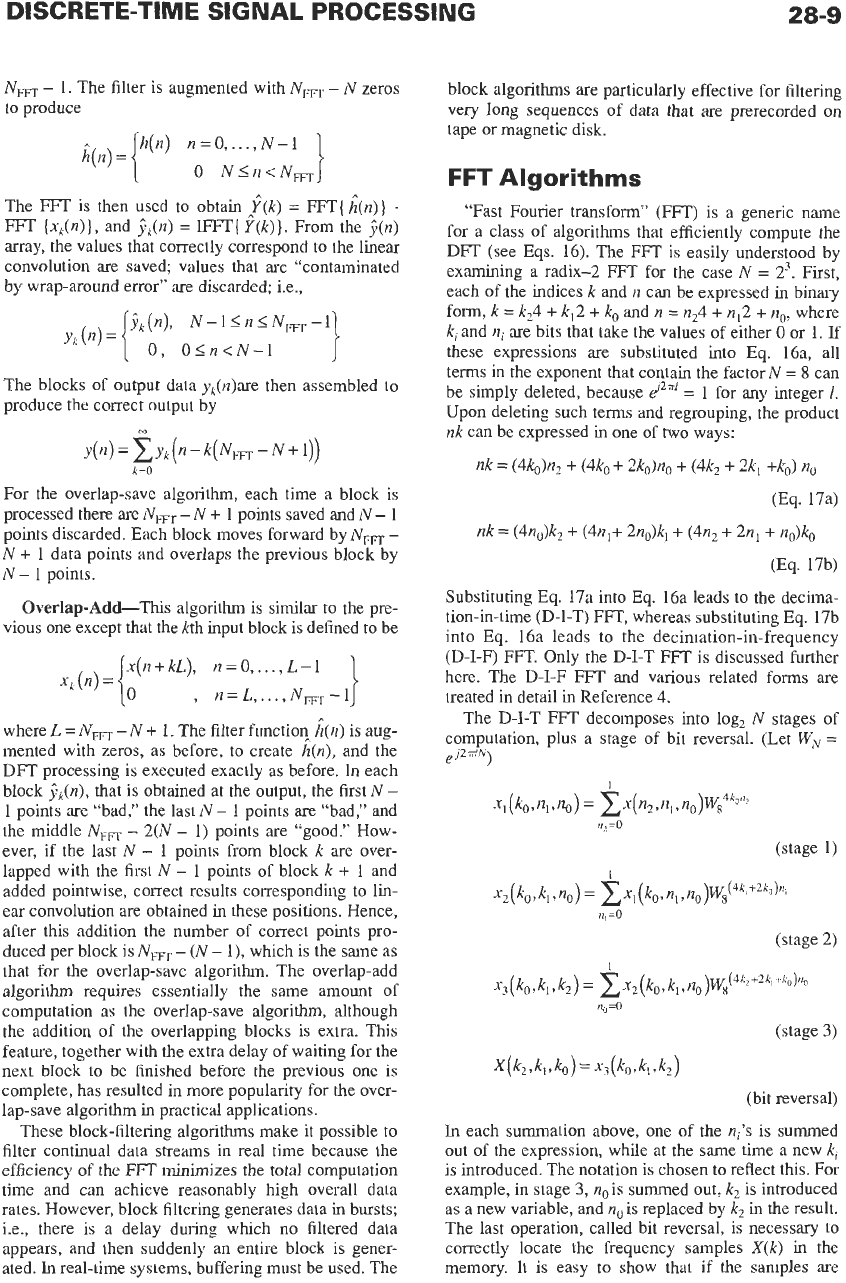
tion. Fig. 3 shows a digital processor complete with
sampling and reconstruction devices at the input and
output.
DISCRETE FOURIER
TRANSFORM
Definitions and Properties
Let
x(n)
be a finite-length sequence of length N. The
discrete Fourier transform (DFT) pair is defined by
N-l
X(k)
=
xx(n)e-j(27i/N)nk
(Eq. 16a)
GO
k=O,..
.
,N-1
and
N-l
x(n)
=
(1/
N)xX(k)ej(2"/N)nk
(Eq. 16b)
n=
0,.
.
.
,
N-
1
k=O
The DFT treats
x(n)
as though it were one period of
a
periodic sequence.
This
is an important feature that
must be handled properly in signal processing to pre-
vent the introduction of artifacts. Important properties
of
the DFT are summarized in Table
3.
The notation
((k))N
denotes the least positive residue of
k
modulo
N,
and
RN(n)
is a rectangular window function such that
R,(n)
=
1
for
n
=
0,.
. .
,
N-
1,
andRN(n)
=
0
for
n
<O
and
n
2
N.
r-------;
Fig.
3.
Elements required
for
the
digital processing of
an
analog signal
28-8
REFERENCE
DATA
FOR ENGINEERS
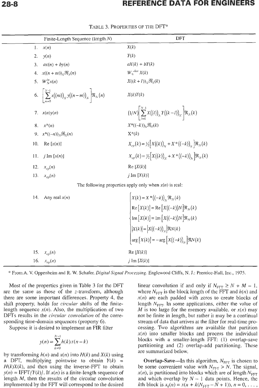
TABLE
3.
PROPERTIES
OF THE
DP"
Finite-Length Sequence (length
N)
DFT
14.
Any
real
x(n)
The following properties apply only when
x(n)
is
real:
*
From
A.
V.
Oppenheim
and
R.
W.
Schafer.
Digital Signal Processing.
Englewood
Cliffs,
N.
J.:
Prentice-Hall,
Inc.,
1975
Most
of the properties given
in
Table
3
for the
DFT
are the same as those of the z-transform, although
there are some important differences. Property
4,
the
shift property, holds for
circular
shifts
of
the finite-
length sequence
x(n).
Also,
the multiplication of two
DFTs
results in the
circular convolution
of the corre-
sponding time-domain sequences (property
6).
Suppose it is desired to implement an
FIR
filter
k=O
by transforming
h(n)
and
x(n)
into
H(k)
and
X(k)
using
a
DFT,
multiplying pointwise to obtain
Y(k)
=
H(k)X(k),
and then using the inverse-FFT to obtain
y(n)
=
IFFT{Y(k)]. If
x(n)
is a finite-length sequence of
length
M,
then the results of the circular convolution
implemented by the
FFT
will correspond to the desired
linear convolution if and only if NET
2
N
+
M
-
1,
where
Nm
is the block length
of
the
FFT
and
h(n)
and
x(n)
are each padded with zeros to create blocks of
length
NFm
In
some applications, either the value
of
M
is
too
large for the memory available, or
x(n)
may
not be finite in length, but rather it may be a continual
stream of data that arrives at the filter for real-time pro-
cessing.
Two
algorithms are available that partition
x(n)
into smaller blocks and process the individual
blocks with a smaller-length
FFT
(1)
overlap-save
partitioning and
(2)
overlap-add partitioning. These
are
summarized below.
Overlap-Save-In
this algorithm,
NFFT
is chosen
to
be some convenient value with
NET
>
N.
The signal,
x(n),
is partitioned into blocks which are of lengthNET
and which overlap by N
-
1
data points. Hence, the
kth block is
xk(n)
=
x(n
+
k(NmT
-
N
+
l)),
n
=
0,
.
.
.
,
28-9
NFm
-
1.
The filter is augmented with
NFFT
-
N
zeros
to produce
The FFT is then used to obtain
f(k)
=
FFT(
h^(n)}
.
FFT
(xk(n)},
and
&(n)
=
EFT{
Y(k)}.
From the
?(n)
array, the values that correctly correspond to the linear
convolution are saved values that are “contaminated
by wrap-around error” are discarded; i.e.,
The blocks of output data y,(n)are then assembled to
produce the correct output by
m
For the overlap-save algorithm, each time a block is
processed there are
Nm
-
N
+
1 points saved and
N
-
1
points discarded. Each block moves forward by
NFFT
-
N
+
1
data points and overlaps the previous block by
N
-
1
points.
Overlap-Add-This
algorithm
is
similar to the pre-
vious one except that the kth input block is defined to be
1
x(n
+
kL),
n
=
0,.
. .
,
L
-
1
,
n=L,
...,
N,,-l
where
L
=
NWT
-
N
+
1.
The filter function^
i(n)
is aug-
mented with zeros, as before, to create h(n), and the
DFT processing is executed exactly as before. In each
block
$&I),
that is obtained at the output, the first
N
-
1
points are “bad,” the last
N
-
1 points are “bad,” and
the middle
NFm
-
2(N
-
1) points are “good.” How-
ever, if the last
N
-
l
points from block
k
are over-
lapped with the first
N
-
1 points of block
k
+
1 and
added pointwise, correct results corresponding to lin-
ear convolution are obtained
in
these positions. Hence,
after this addition the number of correct points pro-
duced per block is
NWT
-
(N
-
1
),
which is the same as
that for the overlap-save algorithm. The overlap-add
algorithm requires essentially the same amount of
computation as the overlap-save algorithm, although
the addition of the overlapping blocks is extra. This
feature, together with the extra delay of waiting for the
next block
to
be finished before the previous one
is
complete, has resulted in more popularity for the over-
lap-save algorithm in practical applications.
These block-filtering algorithms make it possible to
filter continual data streams in real time because the
efficiency
of
the FFT minimizes the total computation
time and can achieve reasonably high overall data
rates. However, block filtering generates data in bursts;
i.e., there
is
a delay during which
no
filtered data
appears, and then suddenly
an
entire block is gener-
ated.
In
real-time systems, buffering must be used. The
block algorithms are particularly effective for filtering
very long sequences of data that are prerecorded
on
tape or magnetic disk.
FFT
Algorithms
“Fast Fourier transform” (FFT) is a generic name
for a class of algorithms that efficiently compute the
DFT (see Eqs. 16). The FFT is easily understood by
examining a radix-2
FFT
for the case
N
=
23. First,
each of the indices
k
and
n
can be expressed in binary
form,
k
=
k24
+
k,2
+
ko
and
n
=
n24
+
n12
+
no,
where
k,
and
ni
are bits that take the values of either
0
or 1. If
these expressions are substituted into Eq. 16a, all
terms in the exponent that contain the factor
N
=
8
can
be simply deleted, because
dZT’
=
1 for any integer
1.
Upon deleting such terms and regrouping, the product
nk
can be expressed in one of
two
ways:
nk
=
(4k0)n2
+
(4k0
+
2k0)n0
+
(44
+
2k1
+ko)
no
(Eq. 17a)
nk
=
(4no)k2
+
(4n,+
2no)kl
+
(4n2
+
2n1
+
no)ko
(Eq. 17b)
Substituting Eq. 17a into Eq. 16a leads
to
the decima-
tion-in-time (D-I-T) FFT, whereas substituting Eq. 17b
into Eq. 16a leads to the decimation-in-frequency
(D-I-F) FFT. Only the D-I-T
FFT
is discussed further
here. The D-I-F
FFT
and various related forms are
treated in detail in Reference
4.
The D-I-T
FFT
decomposes into log,
N
stages
of
computation, plus a stage of bit reversal. (Let
WN
=
e
j
2
dN)
1
x1
(k,,
nl,
no)
=
x(n2,
nl,
n,=O
(stage 1)
1
x2
(
ko
,
kl
,
no)
=
exl
(k,
,
nl,
no)W,(4kl+2ko)nj
I,,
=o
(stage
2)
1
x3(
k,, kl, k,)
=
x2(ko, kl,
n0)W,(4k2’+2k1+k0)n0
“0
=O
(stage
3)
(bit reversal)
In
each summation above, one of the
ni’s
is summed
out of the expression, while at the same time a new
k,
is introduced. The notation is chosen to reflect this. For
example, in stage
3,
no
is summed out,
k,
is introduced
as a new variable, and
no
is replaced by
k2
in the result.
The last operation, called bit reversal, is necessary to
correctly locate the frequency samples
X(k)
in the
memory. It
is
easy
to
show that if the samples are
28-1
0
REFERENCE
DATA
FOR ENGINEERS
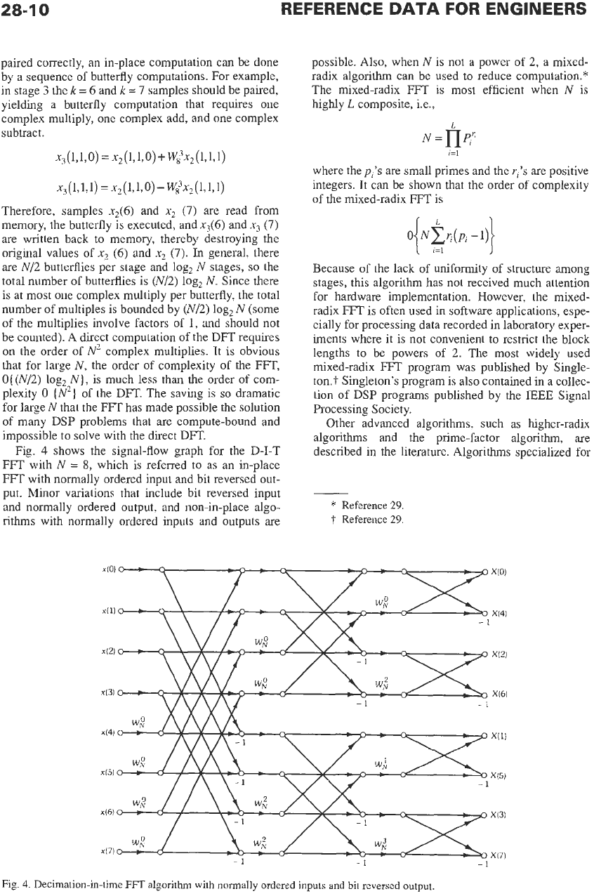
paired correctly, an in-place computation can be done
by a sequence of butterfly computations. For example,
in stage
3
the
k
=
6
and
k
=
7
samples should be paired,
yielding a butterfly computation that requires one
complex multiply, one complex add, and one complex
subtract
.
Therefore, samples
x2(6)
and
x2
(7)
are read from
memory, the butterfly is executed, and
~3(6)
and
x3
(7)
are written back
to
memory, thereby destroying the
original values of
x,
(6)
and
x2
(7).
In
general, there
are N/2 butterflies per stage and log, N stages,
so
the
total number of butterflies is
(N/2)
log, N. Since there
is at most one complex multiply per butterfly, the total
number
of
multiples is bounded by
(N/2)
log, N (some
of the multiplies involve factors of
1,
and should not
be counted). A direct computation of the DFT requires
on the order of
N2
complex multiplies. It is obvious
that for large N, the order of complexity of the FFT,
O{
(N/2)
log, N), is much less than the order of com-
plexity
0
IN2}
of
the
DFT.
The saving is
so
dramatic
for large N that the
FFT
has made possible the solution
of many DSP problems that are compute-bound and
impossible
to
solve with the direct DFT.
Fig.
4
shows the signal-flow graph for the
D-I-T
FFT with N
=
8,
which
is
referred
to
as an in-place
FFT
with normally ordered input and bit reversed out-
put. Minor variations that include bit reversed input
and normally ordered output, and non-in-place algo-
rithms with normally ordered inputs and outputs are
possible. Also, when
N
is not a power of
2,
a mixed-
radix algorithm can be used to reduce computation."
The mixed-radix
FFT
is most efficient when N is
highly
L
composite, Le.,
L
N=l-Jpi'
i=l
where the
pi's
are small primes and the
yi's
are positive
integers. It can be shown that the order of complexity
of the mixed-radix
FFT
is
0
NCG(Pi-1)
{
.1,
1
Because of the lack of uniformity of structure among
stages, this algorithm has not received much attention
for hardware implementation. However, the mixed-
radix
FFT
is often used in software applications, espe-
cially for processing data recorded in laboratory exper-
iments where it is not convenient to restrict the block
lengths to be powers of
2.
The most widely used
mixed-radix
FFT
program was published by Single-
ton.? Singleton's program is also contained in a collec-
tion of DSP programs published by the
IEEE
Signal
Processing Society.
Other advanced algorithms, such as higher-radix
algorithms and the prime-factor algorithm, are
described in the literature. Algorithms specialized for
*
Reference
29.
t
Reference
29.
-1
-1
-1
Fig.
4.
Decimation-in-time
FFT
algorithm with normally ordered inputs and bit reversed
output.
28-1
1
real-valued data lead to
a
reduction at the computa-
tional cost by a factor of two.
A
radix-2 decimation-in-time
FFT
program, written
in
C,
is listed in Chart
1
for reference.
The FFT
in
Spectral Analysis
An FFT program is often used to perform spectral
analysis
on
signals that are sampled and recorded as
part of laboratory experiments, or in certain types
of
data acquisition systems. There are several issues that
should be addressed when spectral analysis is per-
formed on (sampled) analog waveforms that are
observed over a finite interval
of
time.
Windowing-The
FFT
treats the block of data
as
though it is one period of a periodic sequence. If the
underlying waveform is not periodic, then harmonic
distortion may occur because the periodic waveform
created by the
FFT
may have sharp discontinuities.
This
effect is minimized by removing the mean of the
data (it can always be reinserted) and by windowing the
data
so
the ends of the block are smoothly tapered to
zero and discontinuities do not occur when the
FFT
treats the windowed block
as
one period of a periodic
sequence.
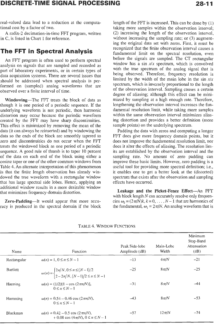
A
good rule of thumb is to taper
10
percent
of the data on each end of the block using either
a
cosine taper or one
of
the other common windows from
Table
4.
An
alternate interpretation of this phenomenon
is that the finite length observation has already win-
dowed the true waveform with a rectangular window
that has large spectral side lobes. Hence, applying an
additional window results in
a
more desirable window
that minimizes frequency-domain distortion.
Zero-Padding-It would appear that more accu-
racy is produced in the spectral domain if the block
length of the FFT is increased. This can be done by
(1)
taking more samples within the observation interval;
(2)
increasing the length of the observation interval,
without increasing the sampling rate; or
(3)
augment-
ing the original data set with zeros. First, it must be
recognized that the finite observation interval causes a
fundamental limit on the spectral resolution, even
before the signals
are
sampled. The CT rectangular
window has
a
sin
xlx
spectrum, which
is
convolved
with the true spectrum of the analog signal that is
being observed. Therefore, frequency resolution is
limited by the width of the main lobe in the sin
xlx
spectrum, which is inversely proportional to the length
of the observation interval. Sampling causes a certain
degree of aliasing; although this effect can be mini-
mized by sampling at a high enough rate. Therefore,
lengthening the observation interval increases the fun-
damental resolution limit, while taking more samples
within the same observation interval minimizes alias-
ing distortion and provides
a
better definition (more
sample points) on the underlying spectrum.
Padding the data with zeros and computing a longer
FFT
does give more frequency domain points, but it
does not improve the fundamental resolution limit, nor
does it alter the effects of aliasing. The resolution lim-
its
are
established by the observation interval and the
sampling rate.
No
amount of zero padding can
improve these basic limits. However, zero padding is a
useful tool for providing more spectral definition; i.e.,
it enables one to get
a
better look at the (distorted)
spectrum that exists after the observation and sampling
effects have occurred.
Leakage and
the
Picket-Fence Effect-An
FFT
with block length
N
can accurately resolve only frequen-
cies
w,
=
(2?r/N)k, k
=
0,
. .
.
,
N
-
1
that are harmonics of
the fundamental,
w1
=
2?r/N.
An
analog waveform that is
TABLE
4.
WINDOW
FUNCTIONS
Minimum
Stop-Bmd
Peak
Side-lobe
Main-Lobe
Attenuation
Name
Function Amplitude (dB) Width
(dB)
Rectangular
w(n)
=
1,O
<n
5
N-
1
-13
4
TIN
-2
1
2n/N,
0
5
n
<
(N
-1)/2 -25
8
T/N
-25
2-2n/N,
(N
-1)/2
5
n
5
N
-1
Bartlett
w(n)=
Hmning
w(n)
=
(1/2)[1
-cos
(2m/N)1,
0
512
5
N-
1
Hamming
o(n)
=
0.54
-
0.46
COS
(2m~/N),
O<n<N-1
-3
1
8
rr1N
-44
43
8
rr1N
-53
Blackman
o(n)
=
0.42
-
0.5
COS
(2m~/N),
-51
12
TIN
-14
+
0.08
cos
(4n/N),
0
5
n
5
N
-
1