Middleton W.M. (ed.) Reference Data for Engineers: Radio, Electronics, Computer and Communications
Подождите немного. Документ загружается.

30-22
REFERENCE DATA FOR ENGINEERS
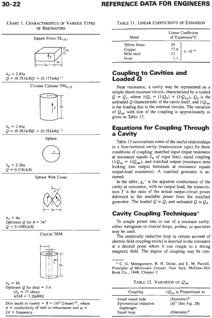
CHART
1.
CHARACTERISTICS
OF
VARIOUS
TYPES
OF
RESONATORS
Square Prism TEi,o,i
A0
=
2.83~
Q
=
(0.353A/6)[1
+
(0.177A/h)]-'
Circular Cylinder TMo,,,,
A.
=
2.61~
Q
=
(0.383A/6)[1
+
(0.192A/h)]-i
Sphere
A,
=
2.28~
Q
=
0.318(A/6)
Sphere With Cones
A0
=
4a
Optimum Q for
0
=
34"
Q
=
0.1095(M6)
Coaxial TEM
I
A,
=
4h
Optimum Q for
(Mu)
=
3.6
(Zo
=
77
ohms)
A/[46
+
7.2(hs/b)]
Skin depth in meters
=
S
=
(107/27rou)"*, where
D
=
conductivity
of
wall in mhosheter and
o
=
27r
X
frequency.
TABLE
11.
LINEAR
COEFFICIENTS OF
EXPANSION
____
Linear Coefficient
of ExuansiodT Metal
Yellow
brass
Copper
Mild steel
Invar
12
1.1
Coupling to Cavities and
Loaded
0
Near resonance, a cavity may be represented as a
simple shunt-resonant circuit, characterized by a loaded
Q
=
Ql,
where
l/Q,
=
(UQ,)
+
(I/Qex,),
Qo
is the
unloaded
Q
characteristic of the cavity itself, and
l/Qex,
is the loading due to the external circuits. The variation
of
Q,,
with size
of
the coupling is approximately as
given in Table
12.
Equations
for
Coupling Through
a Cavity
Table
13
summarizes some of the useful relationships
in a four-terminal cavity (transmission type) for three
conditions of coupling: matched input (input resistance
at resonance
equals
2,
of
input line), equal coupling
(l/Qi,
=
l/Qout),
and matched output (resistance seen
looking into output terminals at resonance equals
output-load resistance).
A
matched generator is as-
sumed.
In the table,
g,'
is the apparent conductance of the
cavity at resonance, with no output load; the transmis-
sion
T
is the ratio
of
the actual output-circuit power
delivered to the available power from the matched
generator. The loaded
Q
is
Ql
and unloaded Q is
Q,.
Cavity Coupling Techniques*
To couple power into or out of a resonant cavity,
either waveguide or coaxial loops, probes, or apertures
may be used.
The essentially inductive loop (a certain amount of
electric-field coupling exists) is inserted in the resonator
at a desired point where it can couple to a strong
magnetic field. The degree of coupling
may
be con-
*
C.
G.
Montgomery,
R.
H.
Dicke, and E. M. Purcell.
Principles
of
Microwave Circuits.
New York: McGraw-Hill
Book
Co., 1948; Chapter
7.
TABLE
12.
VARIATION
OF
Q,,
Coupling l/Qex,
is
Proportional to
Small
round hole (Diameter)6
Symmetrical inductive
Small loop (Diameter)4
(g4
(See Fig. 28)
diaphragm
WAVEGUIDES
AND
RESONATORS
-0
04--
30-23
30
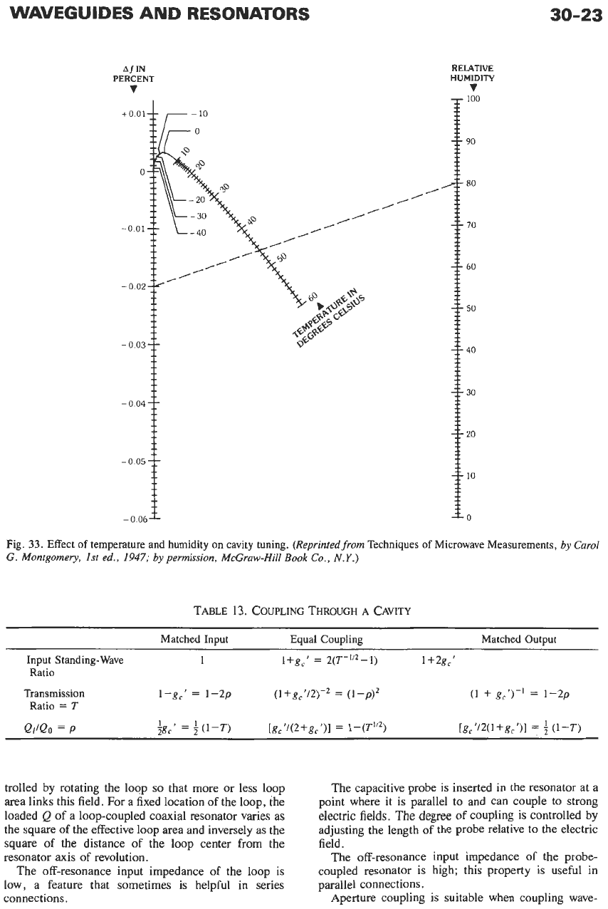
Fig.
33.
Effect
of
temperature and humidity
on
cavity tuning.
(Reprintedfrom
Techniques
of
Microwave Measurements,
by
Carol
G. Montgomery,
1st
ed.,
1947;
by
permission, McGraw-Hill
Book
Co.,
N.Y.)
TABLE
13.
COUPLING
THROUGH
A CAVITY
Matched Input Equal Coupling Matched Output
Input Standing-Wave
1 l+g,’
=
2(T-”Z-1) 1+2g,‘
Ratio
Transmission
l-gc‘
=
1-2p (l+gc’/2)-Z
=
(1-p)Z
Ratio
=
T
(1
+ gc’)-’
=
1-2p
QdQo
=
P
f&!
=
f
(1-T) [gc’/(2+g,’)]
=
1-p)
[gc‘/2(l+gc’)l
=
f
(1-T)
trolled by rotating the loop
so
that more
or
less loop
area links this field. For a fixed location of the loop, the
loaded
Q
of a loop-coupled coaxial resonator varies as
the square
of
the effective loop area and inversely
as
the
square
of
the distance of the loop center from the
resonator
axis
of revolution.
The off-resonance input impedance
of
the loop is
low, a feature that sometimes
is
helpful in series
connections.
The capacitive probe is inserted in the resonator at a
point where it
is
parallel to and can couple to strong
electric fields.
The
degree
of
coupling is controlled by
adjusting the length of the probe relative to the electric
field.
The off-resonance input impedance of the probe-
coupled resonator is high; this property is useful in
parallel connections.
Aperture coupling is suitable when coupling wave-
30-24
REFERENCE DATA
FOR
ENGINEERS
guides to resonators or in coupling resonators together.
In this case, the aperture must be located and shaped to
excite the proper propagating modes.
For all means of coupling, the input impedance at
resonance and the loaded
Q
may be adjusted by proper
selection of the point of coupling and the degree of
coupling.
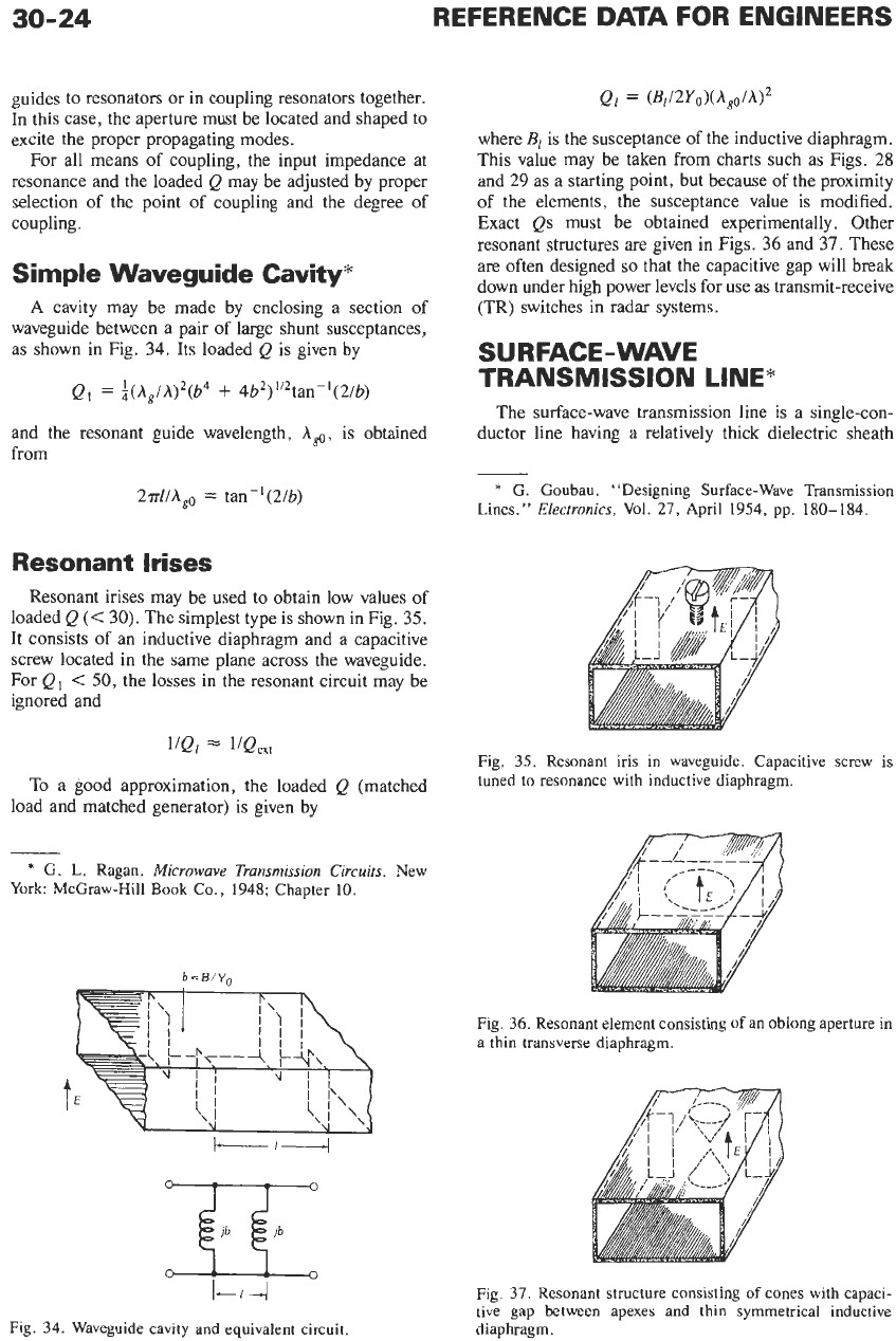
Simple Waveguide Cavity*
A
cavity may be made by enclosing a section
of
waveguide between a pair of large shunt susceptances,
as shown in Fig.
34.
Its loaded
Q
is given by
Q,
=
$(A,/h)’(b4
+
4b2)”’tan-’(2/b)
and the resonant guide wavelength,
A,,,
is obtained
from
2.?rl/A,,
=
tan-](2/b)
Resonant Irises
Resonant irises may be used to obtain
low
values of
loaded
Q
(<
30).
The simplest type is shown in Fig.
35.
It consists of an inductive diaphragm and a capacitive
screw located in the same plane across the waveguide.
For
Q,
<
50,
the losses in the resonant circuit may be
ignored and
l/Qi
1IQm
To
a good approximation, the loaded
Q
(matched
load and matched generator) is given by
*
G.
L.
Ragan.
Microwave Transmission Circuits.
New
York:
McGraw-Hill
Book
Co., 1948; Chapter
10.
b
=
B/Yn
I-/--
Fig. 34. Waveguide cavity and ,equivalent circuit.
Ql
=
(B~~YII)(A,o/A)~
where
B,
is the susceptance of the inductive diaphragm.
This value may be taken from charts such as Figs.
28
and 29 as a starting point, but because of the proximity
of the elements, the susceptance value is modified.
Exact
Qs
must be obtained experimentally. Other
resonant structures
are
given
in
Figs.
36
and
37.
These
are often designed
so
that the capacitive gap will break
down under high power levels for use as transmit-receive
(TR) switches in radar systems.
SU
RFACE
-
WAVE
TRANSMISSION LINE*
The surface-wave transmission line is a single-con-
ductor line having a relatively thick dielectric sheath
*
G. Goubau. “Designing Surface-Wave Transmission
Lines.”
Electronics,
Vol.
27, April 1954, pp.
180-184.
Fig. 35. Resonant iris in waveguide. Capacitive screw is
tuned to resonance with inductive diaphragm.
Fig. 36. Resonant element consisting
of
an oblong aperture in
a thin transverse diaphragm.
Fig. 37. Resonant structure consisting of cones with capaci-
tive gap between apexes and thin symmetrical inductive
diaphragm.
WAVEGUIDES AND RESONATORS
30-25
LAUhCHER DIELECTRIC COATED LAUNCHER
COhDUCTOR
-------
-------
-------
Fig. 39. Surface-wave transmission line with launchers at
each end.
(Courtesy
Electronics.)
.
-
-. .
-
/
-
- -
- -
-
-
-
DIELECTRI~
COPPER
COATING CONDUCTOR
Fig.
38.
Cross
section of surface-wave transmission line.
The losses in the two launchers combined vary from
less than
0.5
decibel to a little more than 1.0 decibel,
according to their design.
Conductor loss
L,
by the equation below is
5
percent
over the theoretical value for pure copper. Dielectric
loss
L,
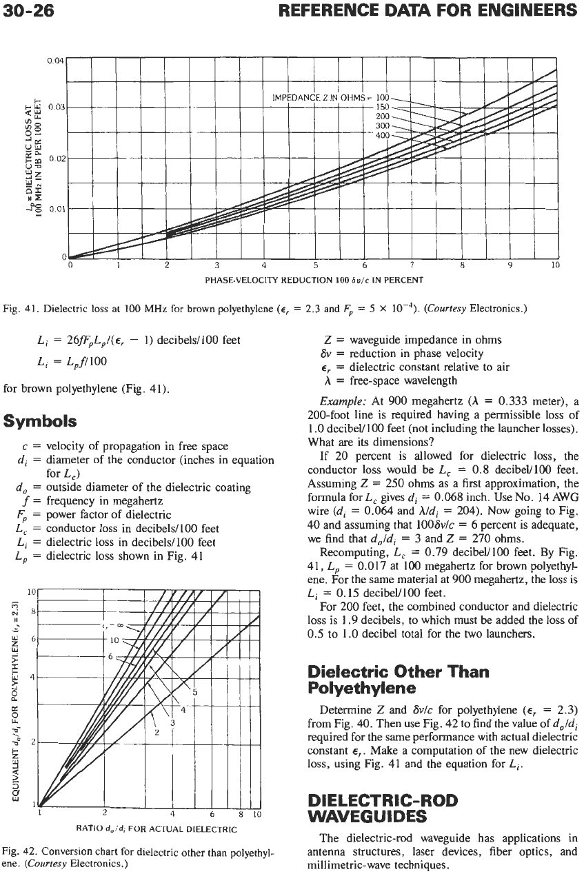
for polyethylene at 100 megahertz is shown in
Fig.
41.
For other dielectrics and frequencies, find
L,
by
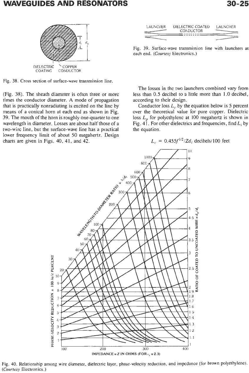
(Fig.
38).
The sheath diameter is often three or more
times the conductor diameter.
A
mode of propagation
that is practically nonradiating
is
excited on
the
line by
means of a conical horn at each end as shown in Fig.
39.
The mouth of the horn is roughly one-quarter to one
wavelength in diameter. Losses are about half those of a
two-wire line, but the surface-wave line has a practical
lower frequency limit of about
50
megahertz. Design
charts are given in Figs.
40,
41,
and
42.
the equation.
L,
=
0.455f
“*:ZdI
1000
decibels/100 feet
Fig.
40.
Relationship among wire diameter, dielectric layer, phase-velocity reduction, and impedance (for brown polyethylene).
(Courtesy
Electronics.)
30-26
REFERENCE
DATA
FOR ENGINEERS
Li
=
26fF,L,/(~,
-
1)
decibels/100 feet
L,
=
L,fllOO
for brown polyethylene (Fig. 41).
Symbols
c
=
velocity of propagation in free space
di
=
diameter of the conductor (inches in equation
do
=
outside diameter of the dielectric coating
f
=
frequency in megahertz
Fp
=
power factor of dielectric
L,
=
conductor loss in decibels1100 feet
L,
=
dielectric
loss
in decibels1100 feet
L,
=
dielectric
loss
shown in Fig. 41
for
L,)
RATIO
doid,
FOR
ACTUAL
DIELECTRIC
Fig.
42.
Conversion chart
for
dielectric other than polyethyl-
ene.
(Courtesy
Electronics.)
Z
=
waveguide impedance in ohms
Sv
=
reduction in phase velocity
E,
=
dielectric constant relative to air
A
=
free-space wavelength
Example:
At 900 megahertz
(A
=
0.333 meter), a
200-foot line is required having a permissible loss of
1
.O
decibeU100 feet (not including the launcher losses).
What are its dimensions?
If 20 percent is allowed for dielectric loss, the
conductor loss would be
L,
=
0.8
decibeVl00 feet.
Assuming
2
=
250
ohms as a first approximation, the
formula for
L,
gives
d,
=
0.068
inch. Use No. 14 AWG
wire
(di
=
0.064
and
hld,
=
204). Now going to Fig.
40 and assuming that
1006v/c
=
6
percent is adequate,
we find that
d,ldi
=
3
and
Z
=
270 ohms.
Recomputing,
L,
=
0.79 decibeL'100 feet. By Fig.
41,
L,
=
0.017 at
100
megahertz for brown polyethyl-
ene. For the same material at 900 megahertz, the loss is
L,
=
0.15
decibeVlO0 feet.
For 200 feet, the combined conductor and dielectric
loss is 1.9 decibels, to which must be added the loss of
0.5
to
1.0 decibel total for the two launchers.
Dielectric Other Than
Polyethylene
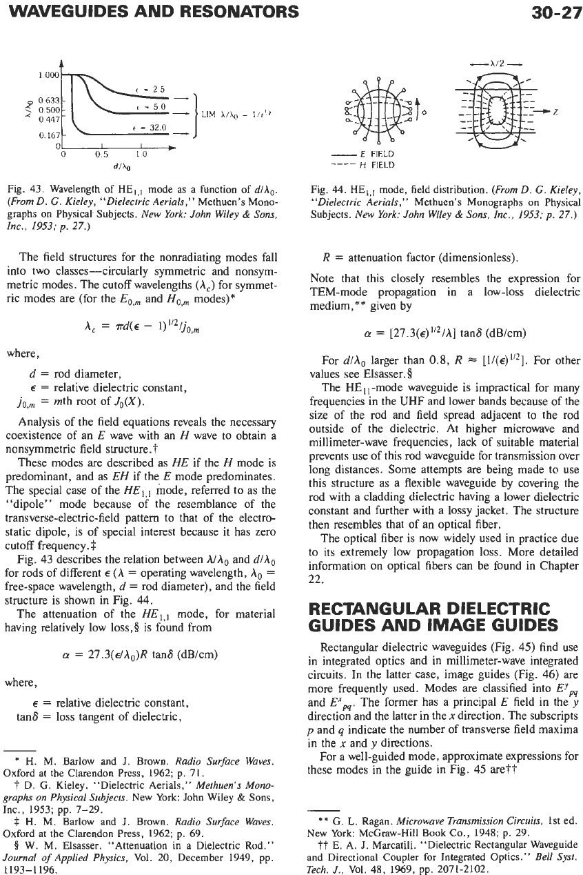
Determine
Z
and
Sv/c
for polyethylene
(E,
=
2.3)
from Fig. 40. Then use Fig.
42
to find the value of
d,ld,
required for the same performance with actual dielectric
constant
E,.
Make a computation of the new dielectric
loss,
using Fig.
41
and the equation for
Li.
DIELECTRIC-ROD
WAVEGUIDES
The dielectric-rod waveguide has
applications in
antenna structures, laser devices, fiber optics, and
millimetric-wave techniques.
WAVEGUIDES AND RESONATORS
30-27
0
O
167c-
0
05
10
dlhg
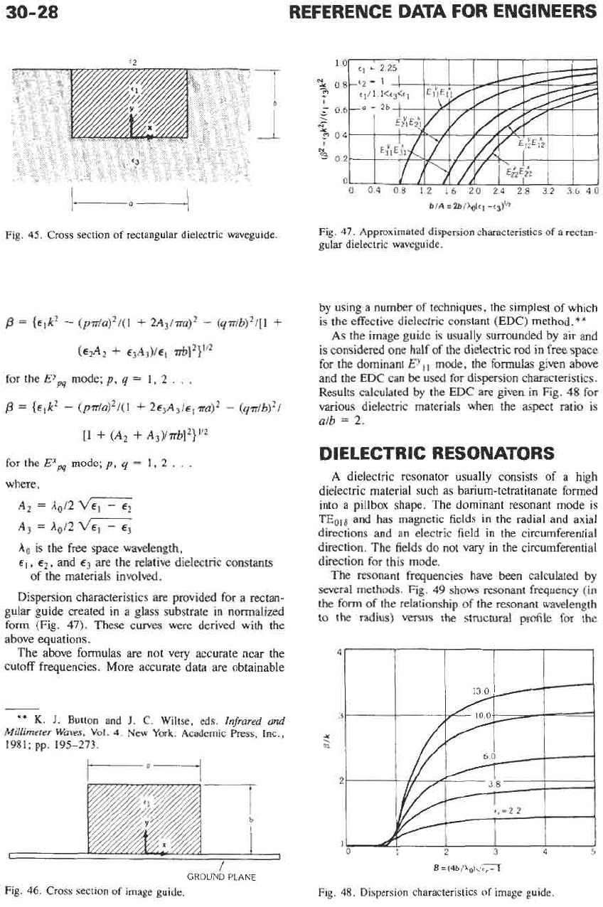
Fig.
43.
Wavelength
of
HEI,I mode
as
a function
of
dlh,.
(From
D.
G.
Kieley, “Dielectric Aerials,”
Methuen’s
Mono-
graphs
on
Physical Subjects.
New York: John Wiley
&
Sons,
lnc., 1953; p.
27.)
The field structures for the nonradiating modes fall
into two classes-circularly symmetric and nonsym-
metric modes. The cutoff wavelengths
(A,)
for symmet-
ric modes are (for the
Eo,m
and
Ho,m
modes)*
where,
d
=
rod diameter,
E
=
relative dielectric constant,
jo,m
=
mth root of
Jo(X).
Analysis of the field equations reveals the necessary
coexistence of an
E
wave with an
H
wave to obtain a
nonsymmetric field structure.?
These modes are described as
HE
if the
H
mode is
predominant, and as
EH
if the
E
mode predominates.
The special case of the
HE,,,
mode, referred to as the
“dipole” mode because of the resemblance of the
transverse-electric-field pattern to that of the electro-
static dipole, is of special interest because it has zero
cutoff frequency.
?:
Fig.
43
describes the relation between
MAo
and
d/Ao
for rods of different
E
(A
=
operating wavelength,
A,
=
free-space wavelength,
d
=
rod diameter), and the field
structure is shown in Fig.
44.
The attenuation of the
HE,,,
mode, for material
having relatively low
loss,§
is found from
a
=
27.3(~/A,)R
tan8 (dB/cm)
where,
E
=
relative dielectric constant,
tan8
=
loss tangent of dielectric,
*
H.
M. Barlow
and
J. Brown.
Radio Surface Waves.
Oxford
at
the
Clarendon Press,
1962;
p.
71.
t
D.
G.
Kieley. “Dielectric Aerials,”
Methuen’s Mono-
graphs
on
Physical Subjects.
New
York:
John
Wiley
&
Sons,
Inc.,
1953;
pp.
7-29.
H.
M.
Barlow
and
J. Brown.
Radio Su$ace Waves.
Oxford
at
the
Clarendon
Press,
1962;
p.
69.
5
W.
M.
Elsasser. “Attenuation
in
a
Dielectric Rod.”
Journal of Applied Physics,
Vol.
20,
December
1949,
pp.
1193-1 196.
-
E
FIELD
H
FIELD
__-_
Fig.
44.
HE,,, mode, field distribution.
(From
D.
G.
Kieley,
“Dielectric Aerials,”
Methuen’s Monographs
on
Physical
Subjects.
New York: John Wiley
&
Sons,
Inc., 1953; p.
27.)
R
=
attenuation factor (dimensionless).
Note that this closely resembles the expression for
TEM-mode propagation in a low-loss dielectric
medium,** given by
a
=
[27.3(~)”*/A]
tan8 (dB/cm)
For
d/Ao
larger than
0.8,
R
=
[1/(~)”*].
For other
values see Elsasser.
5
The HE
I
I
-mode waveguide is impractical for many
frequencies in the
UHF
and lower bands because of the
size of the rod and field spread adjacent to the rod
outside of the dielectric. At higher microwave and
millimeter-wave frequencies, lack of suitable material
prevents use of this rod waveguide for transmission over
long distances. Some attempts are being made to use
this structure as a flexible waveguide by covering the
rod with a cladding dielectric having a lower dielectric
constant and further with a lossy jacket. The structure
then resembles that of an optical fiber.
The optical fiber is now widely used in practice due
to its extremely low propagation loss. More detailed
information on optical fibers can be found in Chapter
22.
RECTANGULAR DIELECTRIC
GUIDES AND IMAGE GUIDES
Rectangular dielectric waveguides (Fig.
45)
find use
in integrated optics and in millimeter-wave integrated
circuits. In the latter case, image guides (Fig.
46)
are
more frequently used. Modes are classified into
EYpq
and
Expq.
The former has a principal
E
field in the
y
direction and the latter in the
x
direction. The subscripts
p
and
q
indicate the number of transverse field maxima
in the
x
and
y
directions.
For a well-guided mode, approximate expressions for
these modes in the guide in Fig.
45
are??
**
G.
L.
Ragan.
Microwave Transmission Circuits,
1st
ed.
New
York:
McGraw-Hill
Book
Co.,
1948;
p.
29.
t?
E. A.
J.
Marcatili.
“Dielectric Rectangular Waveguide
and
Directional Coupler
for
Integrated Optics.
”
Bell
Syst.
Tech.
J.,
Vol.
48,
1969,
pp.
2071-2102.
30-28
REFERENCE
DATA
FOR ENGINEERS
-_
‘2
4
0
1
‘3
a--
--
Fig
45
Cross
sectlon
of
rectangular dielectric waveguide
[l
+
(A2
+
A3)/~b]2}”2
for the
EX,
mode;
p,
q
=
1,
2
. .
.
where,
A2
=
Ao/2
A,
=
Ao/2
A.
is the free space wavelength,
E],
e2,
and
E,
are the relative dielectric constants
of
the materials involved.
Dispersion characteristics are provided for a rectan-
gular guide created in a glass substrate in normalized
form
(Fig.
47).
These curves were derived with the
above equations.
The above formulas are not very accurate near the
cutoff frequencies. More accurate data are obtainable
**
K.
J.
Button and
J.
C.
Wiltse, eds.
Infrared and
Millimeter
Waves,
Vol.
4.
New York: Academic Press, Inc.,
1981;
pp.
195-273.
I
GROUND
PLANE
Fig.
46.
Cross
section
of
image guide.
0 04
08
12
16
20 24
28 32
36
40
Fig.
47.
Approximated dispersion characteristics
of
a
rectan-
gular
dielectric waveguide.
by using a number of techniques, the simplest of which
is the effective dielectric constant (EDC) method.
**
As
the image guide is usually surrounded by air and
is considered one half of the dielectric rod in free. space
for the dominant
EYll
mode, the formulas given above
and the EDC can be used for dispersion characteristics.
Results calculated by the EDC are given in Fig.
48
for
various dielectric materials when the aspect ratio is
alb
=
2.
DIELECTRIC RESONATQRS
A
dielectric resonator usually consists of a high
dielectric material such as barium-tetratitanate formed
into a pillbox shape. The dominant resonant mode
is
TEols and has magnetic fields in the radial and axial
directions and an electric field in the circumferential
direction. The fields do not
vary
in the circumferential
direction for this mode.
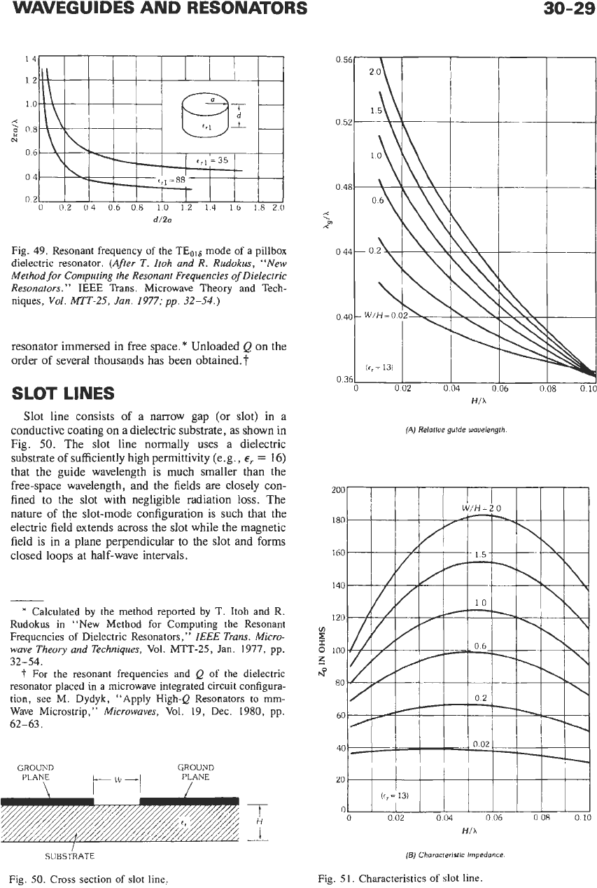
The resonant frequencies have been calculated by
several methods. Fig.
49
shows resonant frequency (in
the form of the relationship of the resonant wavelength
to
the radius) versus the structural profile for the
3
5
m
2
1
0
2
3
4
5
I
B
=
(4b&)d-
Fig.
48.
Dispersion characteristics
of
image guide.
WAVEGUIDES AND RESONATORS
30-29
14
12
10
rc
,
N
g
08
06
04
02
0
02
04
06 08
10
12
14
Ib
18
20
Fig. 49. Resonant frequency
of
the TEol8 mode of a pillbox
dielectric resonator.
(After
T.
Itoh and R. Rudokus, “New
Method for Computing the Resonant Frequencies
of
Dielectric
Resonators.”
IEEE Trans. Microwave Theory and Tech-
niques,
Vol. MTT-25,
Jan.
1977;
pp.
32-54.)
resonator immersed in free space.
*
Unloaded
Q
on the
order of several thousands has been 0btained.t
SLOT
LINES
Slot line consists of a narrow gap (or slot) in a
conductive coating on a dielectric substrate, as shown in
Fig.
50.
The slot line normally uses a dielectric
substrate of sufficiently high permittivity (e.g.,
E,
=
16)
that the guide wavelength is much smaller than the
free-space wavelength, and the fields are closely con-
fined to the slot with negligible radiation loss. The
nature of the slot-mode configuration is such that the
electric field extends across the slot while the magnetic
field is in a plane perpendicular to the slot and forms
closed loops at half-wave intervals.
SUBS~RATE
Fig. 50. Cross section of slot line,
HI1
(A)
Relatlue gulde Wavelength
*
Calculated by the method reported by T. Itoh and R.
Rudokus in “New Method for Computing the Resonant
Frequencies
of
Dielectric Resonators,”
ZEEE
Trans. Micro-
wave Theory and Techniques,
Vol. MTT-25,
Jan.
1911, pp.
32-54.
t
For the resonant frequencies and
Q
of
the dielectric
resonator placed in a microwave integrated circuit configura-
tion, see M. Dydyk, “Apply High-Q Resonators to mm-
Wave Microstrip,”
Microwaves,
Vol. 19, Dec. 1980, pp.
62-63.
GROUND
GROUND
PLANE
\
PLANE
/
[B)
Characteristic Impedance.
Fig. 51. Characteristics
of
slot line.
30-30
REFERENCE
DATA
FOR
ENGINEERS
Since the slot mode
is
a
non-TEM
wave, the defini-
tion
of
characteristic impedance is not unique. One
definition could be
z,
=
V212P
where,
V is
the peak voltage amplitude across the slot,
P
is the average power flow
of
the wave.
For the intervals given by
9.6
5
E,
5
20,
0.02
5
WIH
5
2.0,
and
0.015
5
HIA
5
0.08
and an
infinitesimally thin ground plane, a closed-form ap-
proximation to
A,lA
(where
A,
is the guide wavelength
and
A
is
the free-space wavelength) can be expressed as*
A,lA
=
fi(~,)&(WIh)
+
f3(W/h)(H/h)f4(W’H)
+
fs(WlH))
*
C.
M. Krowne. “Approximations to
Hybrid
Mode
Slot
Line Behavior.”
Electronics Letters,
Vol.
14,
13
April
1978,
pp.
258-259.
SUBSTRATE
e,
WAVEGUIDE
(A/ Unllaterol
I
1
I-lBCI
m
(C)
Anrlpodal
Figb
52.
Cross
sections
of
fin-lines.
0
51
I I
I
1
0
05
10
15
IS/
IN
MILLIMETERS
(A) Dielectric constant
400
300
VI
I
0
200
f3
UNILATERAL
100
0
0.5
1
.o
IS1
IN
MILLIMETERS
(E)
Characterlrtic Impedance.
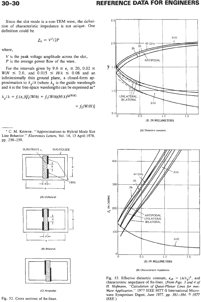
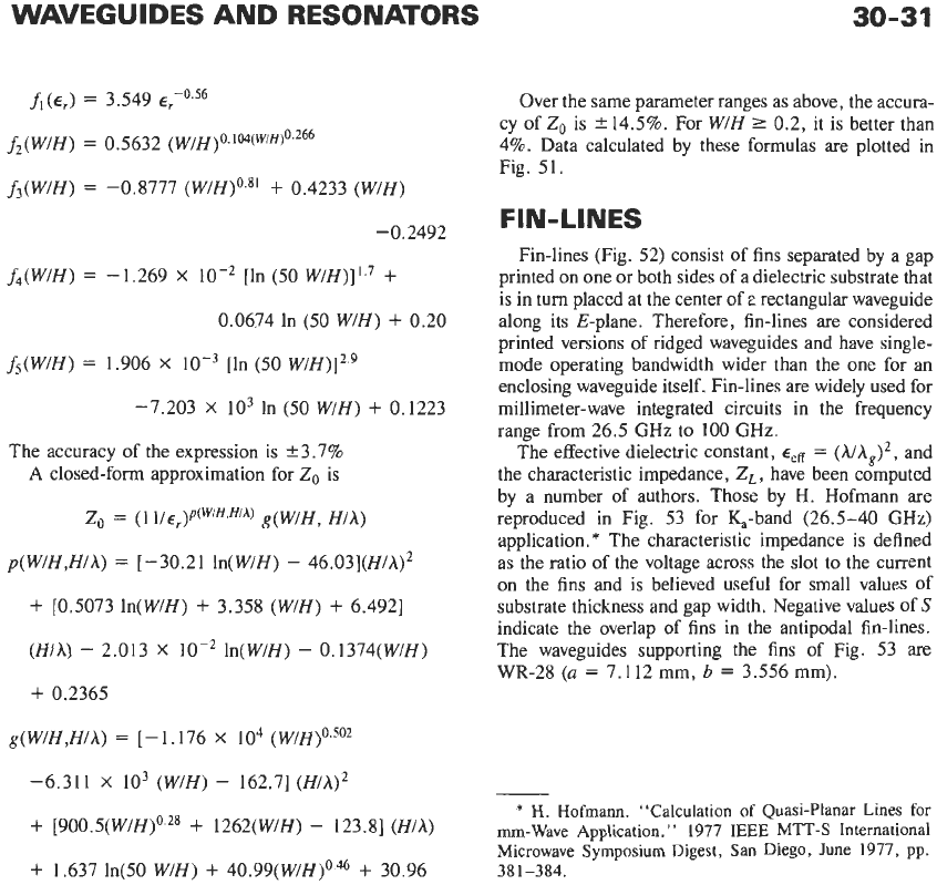
Fig.
53.
Effective dielectric constant,
E,~
=
and
characteristic impedance
of
fin-lines.
(From Figs.
3
and
4
of
H. Hofmann, “Calculation
of
Quasi-Planar Lines
for
mm-
Wave Application,”
1977
IEEE
MTT-S International Micro-
wave Symposium Digest,
June
1977,
pp.
381-384.
@
1977
IEEE.)
WAVEGUIDES AND RESONATORS
30-31
A(€,)
=
3.549
€,456
f2(W/H)
=
0.5632 (W/H)o.’04(W‘H)o’266
f3(W/H)
=
-0.8777 (W/H)o.8’
+
0.4233 (WIH)
-0.2492
f4(W/H)
=
-1.269
X
lo-’ [In
(50
W/H)]1.7
+
0.0674 In
(50
WIH)
+
0.20
&(W/H)
=
1.906
X
[In
(50
W/H)]2.9
-7.203
X
lo3
In (50 WIH)
+
0.1223
The accuracy of the expression is ‘3.7%
A
closed-form approximation for
Zo
is
Zo
=
(1 ~/E,)P(~’~.”’~) g(W/H, Hlh)
p(W/H,H/A)
=
[-30.21 ln(W/H)
-
46.03](H/h)’
+
[0.5073 In(W/H)
+
3.358 (W/H)
+
6.4921
(Hlh)
-
2.013
X
lo-’
ln(WlH)
-
0.1374(W/H)
+
0.2365
g(W/H,H/h)
=
[-1.176
X
lo4 (W/H)0.502
-6.311
X
lo3 (WIH)
-
162.71 (H/A)’
+
[900.5(WlH)o.28
+
1262(W/H)
-
123.81 (Hlh)
+
1.637 ln(50 WIH)
+
40.99(W/H)0.46
+
30.96
Over the same parameter ranges as above, the accura-
cy of
Zo
is
2
14.5%. For W/H
2
0.2, it is better than
4%. Data calculated by these formulas are plotted in
Fig. 51.
FIN-LINES
Fin-lines (Fig.
52)
consist of fins separated by a gap
printed on one or both sides of a dielectric substrate that
is in turn placed at the center of
e
rectangular waveguide
along its E-plane. Therefore, fin-lines are considered
printed versions of ridged waveguides and have single-
mode operating bandwidth wider than the one for an
enclosing waveguide itself. Fin-lines are widely used for
millimeter-wave integrated circuits in the frequency
range from 26.5
GHz
to 100
GHz.
The effective dielectric constant,
E,#
=
(A/h,)’,
and
the characteristic impedance,
Z,
,
have been computed
by a number of authors. Those by
H.
Hofmann are
reproduced in Fig. 53 for &-band (26.5-40
GHz)
application.
*
The characteristic impedance is defined
as the ratio of the voltage across the slot to the current
on the fins and is believed useful for small values of
substrate thickness and gap width. Negative values of
S
indicate the overlap of fins in the antipodal fin-lines.
The waveguides supporting the fins of Fig. 53 are
WR-28
(a
=
7.112 mm,
b
=
3.556 mm).
-
*
H.
Hofrnann. “Calculation
of
Quasi-Planar Lines for
mrn-Wave Application.
”
1977
IEEE
MTT-S International
Microwave Symposium Digest, San Diego, June 1977, pp.
381-384.