Middleton W.M. (ed.) Reference Data for Engineers: Radio, Electronics, Computer and Communications
Подождите немного. Документ загружается.


31
Scattering Matrices
Georges
A.
Deschamps and John
D.
Dyson
Amplitude of a Traveling Wave
31-2
Reflection Coefficient
31-2
Definition
Measurement
Scattering Matrix of a Junction
31-3
Definition
Properties
Change
of
Terminal Plane
Two-Port Junctions
31-3
Transformation Matrix
31-3
Measurement of the Scattering Matrix
31-4
Geometry of Reflection Charts
31-6
Conformal Charts
Projective Chart
Evaluation of Hyperbolic Distance
31-6
Problem A
Problem
B
Problem C
Correspondences With Current, Voltage, and Impedance
Viewpoints
31-9
Normalized Current and Voltage
Current and Voltage Not Normalized
Normalized Impedance and Admittance
Impedance and Admittance Matrix of a Junction
Transformation Matrix
31 -10
31
-1
31
-2
Microwave structures are characterized by dimen-
sions that are of the order
of
the wavelength of the
propagated signal. The notions of current, voltage, and
impedance, useful at lower frequencies, have been
successfully extended to these structures, but these
quantities are not as directly available for measurement;
there are no voltmeters or ammeters and no apparent
“terminal pair” between which to connect them. The
electromagnetic field itself, distributed throughout a
region, becomes the relevant quantity.
Within uniform structures, which are the usual form
of waveguides, the
powerflow
and the
phase
of
the field
at a cross section are the quantities of importance. The
most usual form of measurement, that of the standing-
wave pattern in a slotted section, is easily interpreted in
terms of
traveling
waves and gives directly the
reflection
coeficient.
The scattering description
of
waveguide
junctions was introduced* to express this point of view.
It is not, however, restricted to microwaves; a low-
frequency network can be considered as a “waveguide
junction” between transmission lines connected to its
terminal pairs, and the scattering matrix is a useful
complement to the impedance and admittance descrip-
tions.
AMPLITUDE OF A
TRAVELING WAVE
In a uniform transmission line a traveling wave is
characterized, for a given mode and frequency, by the
electromagnetic-field distribution in a transverse cross
section and by a propagation constant
h.
The field in
any other cross section, at a distance
z
in the direction
of propagation, has the same pattern but is multiplied
by exp
(-jhz).
A wave propagating in the opposite
direction, for the same mode and frequency, varies with
z
as exp
(Jhz).
When losses are negligible,
h
is real.
The
amplitude
of a traveling wave, at a given cross
section in the waveguide, is a complex number
a
defined as follows. The square
la1
of the magnitude of
a
is the power flow,** that is, the integral of the
Poynting vector over the waveguide cross section. The
phase angle of
a
is that of the transverse field in the
cross section.
t
The amplitude of a given traveling wave varies with
z
as exp
(-jhz).
The wave amplitude has the dimensions of the square
root of a power. The meter-kilogram-second unit is
therefore the (watt)
”*.
*
C.
G.
Montgomery,
R.
H.
Dicke, and
E.
M. Purcell,
Principles
of
Microwave Circuits
(New York: McGraw-Hill
Book
Co.,
1948).
*
*
The am litude is sometimes defined to make the power
flow equal to
2
la1
’
rather than
to
la1
’.
This would correspond
to the
use
of
peak values instead
of
root-mean-square values.
i‘
This phase is well defined for a pure mode, since the field
has the same phase everywhere in the cross section.
P
REFLECTION COEFFICIENT
Definition
At a cross section in a waveguide, the reflection
coefficient
W
(also often represented by
r)
is the ratio of
the amplitudes of the waves traveling respectively in the
negative and positive directions.
The positive direction must be specified and is
usually taken as toward the load. To give a definite
phase to the reflection coefficient, a convention
is
necessary that describes how the phases of waves
traveling in opposite directions are to be compared. The
usual convention is to compare in the two waves the
phases of the transverse electric-field vectors.$
For a short-circuit, produced, for instance, by a
perfect conducting plane placed across the waveguide,
the reflection coefficient is
W
=
-1. For an open
circuit, it is
W
=
+
1;
and for a matched load, it is
W
=
0.
When the cross section is displayed by
z
in the
positive direction, the reflection coefficient
W
becomes
W’
=
W
exp
(2Jhz)
0%. 1)
Measurement
In a slotted waveguide equipped with a sliding
voltage probe,* the position of a maximum is one where
the phase of the reflection coefficient is zero.
The ratio of the maximum to the minimum (the
standing-wave ratio, or swr) is
(swr)
=
(1
+
lWI)/(l
-
Iw~)
Therefore
W
=
[(swr)
-
l]/[(swr)
+
11 (Eq.
2)
is the value of
W
at the position of a maximum. At the
position of a minimum, which is easier to locate in
practice, the reflection coefficient is [l
-
(swr)]/[l
+
(swr)l.
At any other position, the value of
W
is obtained by
applying Eq. (1). If the reflection coefficient is wanted
in some waveguide connected to the slotted section, a
good match must obtain at the transition, or a correction
must be applied as explained later in problems A and B
(pages 31-6 to 31-8).
Reflectometers that give the reflection coefficient by
direct reading, or display it on a Smith chart, are in
current use.
$
The dual convention, based on the magnetic-field vector,
would give the “current” reflection coefficient, equal
to
minus the “voltage” reflection coefficient. The latter is used
almost exclusively, and the “voltage”
is implicit.
*
A
probe that gives a reading proportional to the electric
field.
SCATTERING MATRICES
31
-3
SCATTERING MATRIX OF A
JUNCTION
Definition
To define accurately the waves incident on a wave-
guide junction and those reflected (or scattered) from it,
some reference locations must be chosen in the wave-
guides. These locations are called the ports? of the
junction. In a waveguide that can support several
propagating modes, there should be as many ports as
there are modes. (These ports may or may not have the
same physical location in the multimode waveguide.)
At each port i of a junction, consider the amplitude
ai
of
the incident wave traveling toward the junction, and
the amplitude
b,
of the scattered wave, traveling away
from it. As a consequence of Maxwell’s equations,
there exists a linear relation between the
b,
and the
ai.
Considering the
ai
(where i varies from
1
to
n)
as the
components of a vector
a,
and the
bi
as the components
of a vector
b,
this relation can be expressed by
b
=
Sa
where
S
=
(sij) as an
n
X
n
matrix called the scattering
matrix of the junction.
The
sii
is the rejection coeficient looking into port i,
and
sij
is the transmission coeflcient from
j
to i, all
other ports being terminated in matching impedances.
Properties
For a reciprocal junction, the transmission coefficient
from
i
to
j
equals that from
j
to i; the matrix
S
is
symmetrical.
S=S
where
S
denotes the transpose
of
S.
The total power incident on the junction is
The total power scattered is
For
a lossless junction, these two powers are equal
/a12
=
[biz
This implies that the matrix
S
is unitary (see “Matrix
Algebra” in Chapter
47).
t
At
lower frequencies,
for
a network connecting transmis-
sion lines,
a
port
is
a terminal pair.
St
=
s-‘
For apassivejunction with losses,
lbI2
<
[ai2,
hence
the matrix
1
-
SS?
is positive definite.
Change of Terminal Plane
If the port in
arm
i is moved away from the junction
by
di
electrical radians, the scattering matrix becomes
S’
=
@S@
(Eq.
3)
I’
’
.
.
...
I
L.
. .
.
.J
TWO-PORT JUNCTIONS
The two-port junction includes the case of an obsta-
cle or discontinuity placed in a waveguide as well as that
of two essentially different waveguides connected to
each other.
If reciprocity applies, the scattering matrix
is symmetrical
s21
=
SI2
For a lossless junction, the scattering coefficients can
be expressed by
sII
=
+
tanh
(u/2)
exp
(-2ja)
s22
=
-
tanh
(u/2)
exp
(-2jp)
sI2
=
+
sech
(u/2)
exp
[-j(a
+
p)]
0%.
6)
in terms of three parameters,
u, a,
and
p.
This corresponds to the representation of the junction
by an ideal transformer with transformer ratio
n
=
exp
(-u/2),
of hyperbolic amplitude
u,
placed between two
sections of transmission line with electrical lengths
a
and
/3,
respectively.
The quantity
-20
log,,
IsI21
is the insertion loss.
TRANSFORMATION MATRIX
To find the effect of successive obstacles in a wave-
guide or to combine two-port junctions placed in
cascade, it
is
convenient to introduce the wave transfor-
mation matrix
T.
This matrix
T
relates the traveling
31 -4
REFERENCE
DATA
FOR ENGINEERS
E2
OUTPUT
51
INPUT
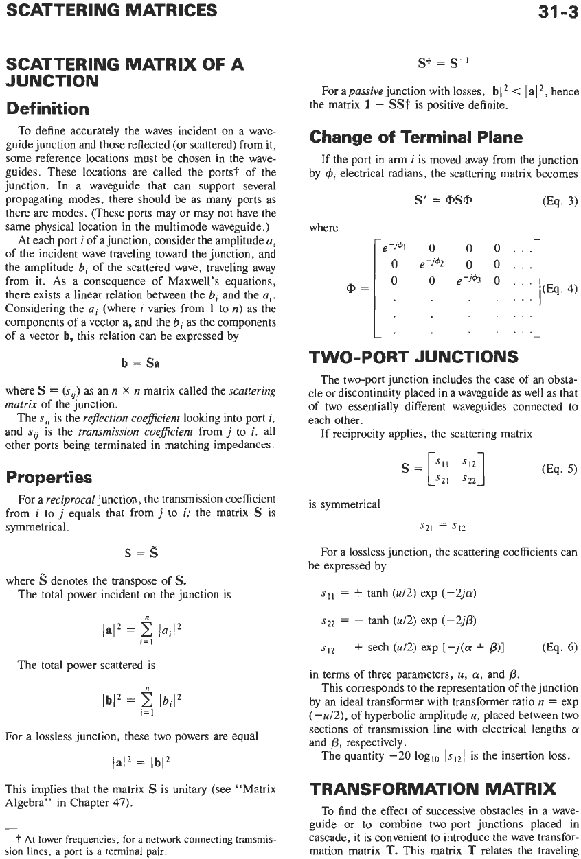
Fig.
1.
Convention for wave transformation matrix
T.
waves on one side of the junction to those
on
the other
side. Using the notations of Fig.
1
The 2
X
2
transformation matrix
T
may be deduced
from the scattering matrix
S
Conversely, if
T
=
(to),
the scattering matrix is
When reciprocity applies to the junction
det
T
=
sl2/sZl
(Eq.
10)
becomes unity.
to the load reflection coefficient
W
=
B2/A2
by
The input reflection coefficient
W’
=
B, /Al
is related
W‘
=
(t2I
+
t22W)/(tll
+
tl2
W)
=
SI1
+
[S]?W/(l
-
S22W)]
(Eq. 11)
(Eq. 12)
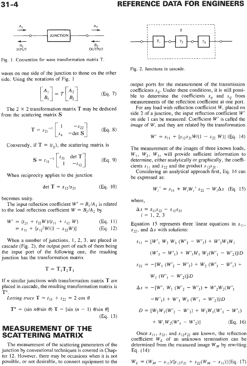
When a number of junctions,
1,
2, 3, are placed in
cascade (Fig.
2),
the output port of each of them being
the input port
of
the following one, the resulting
junction has the transformation matrix
If
n
similar junctions with transformation matrix
T
are
placed in cascade, the resulting transformation matrix is
T“
.
Letting
trace
T
=
tll
+
t22
=
2
cos
8
T”
=
(sin n0/sin
8)
T
-
[sin
(n
-
1)
8/sin
01
(Eq. 13)
MEASUREMENT
OF
THE
SCATTERING MATRIX
The measurement
of
the scattering parameters of the
junction by conventional techniques is covered in Chap-
ter 12. However, there may be occasions when it is not
possible, or not desirable, to connect equipment to the
Fig.
2.
Junctions
in
cascade.
output ports for the measurement of the transmission
coefficients
s
jj.
Under these conditions, it is still possi-
ble to determine the coefficients
sii
and
sij
from
measurements of the reflection coefficient at one port.
For any load with reflection coefficient
W,
placed
on
side
2
of a junction, the input reflection coefficient
W’
on side
1
can be measured. Coefficient
W’
is called the
image
of
W,
and they are related by the transformation
W’
=
SI,
+
[~12~21W/(1
-
~22
W)]
(Eq. 14)
The measurement of the images of three known loads,
W,
,
W2, W3,
will provide sufficient information to
determine, either analytically or graphically, the coeffi-
cients
sI1
and
s22
and the product
sI2s2,.
Considering an analytical approach first, Eq. 14 can
be expressed as:
where,
As
=
SllS22
-
SI2SZI
i=
1,2,3
Equation
15
represents three linear equations in
sI1,
sZ2,
and
As
with solutions:
SI1
=
[W’,
w2
w3
(W’2
-
W‘3)
+
W‘,W3WI
(W‘3
-
W’I)
+
W‘,WI W,(W’,
-
W’,)]/D
s22
=
-[W, (W’2
-
W‘3)
+
w,
(Wf3
-
w’l)
+
w3
(W’,
-
W’,)]/D
AS
=
-[W’I Wl (W’z
-
W’3)
+
W12W2(W’3
-W’,)
+
W‘3
w3
(w’l
-
W’,)]/D
D
=
[W2W3(W’,
-
W’3)
+
W3W1(W’,
-
WfI)
+
wlw,(w’1
-
W’2)I
(Eq. 16)
Once
sI1,
s22,
and
sI2sz2
are known, the reflection
coefficient
W,
of an unknown termination can be
determined from the measured image
WM
by rewriting
Eq.
(14):
WL
=
(WM
-
SI~)/[~I~SZI
+
~22(W,
-
sii)l(Eq.
17)
SCATTERING MATRICES
31
-5
Solutions to
Eq.
14 can also be obtained graphical-
ly.* Doing
so
provides an insight into the transforma-
tion of
W
into its image
W’.
The images of various
known loads can be plotted on a reflection chart and the
scattering coefficients deduced by the following
procedures.
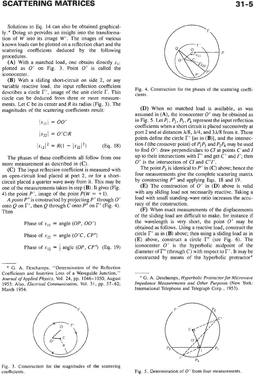
(A)
With a matched load, one obtains directly
sl,
plotted as
0’
on Fig.
3.
Point
0‘
is called the
iconocenter.
(B)
With a sliding short-circuit on side
2,
or any
variable reactive load, the input reflection coefficient
describes a circle
r‘,
image of the unit circle
I?.
This
circle can be deduced from three or more measure-
ments. Let
C
be its center and R its radius (Fig.
3).
The
magnitudes of the scattering coefficients result:
ISllI
=
00’
Is221
=
O’CIR
IS12I2
=
R(1
-
lS22I2)
(Eq.
18)
The phases of these coefficients all follow from one
more measurement as described in
(C).
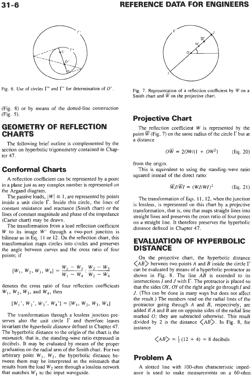
(C)
The input reflection coefficient is measured with
an open-circuit load placed at port
2,
or for a short-
circuit placed a quarter wave away from it. This may be
one of the measurements taken in step
(B).
It gives (Fig.
4) the point
P‘,
image of the point
P(W
=
+
1).
A
point
P’’
is constructed by projecting
P‘
through
0‘
onto
Q
on
r’,
then
Q
through
C
onto
P“
on
r‘
(Fig.
4).
Then
Phase of
sI1
=
angle
(OP,
00’)
Phase of
sZ2
=
angle
(O’C,
CP”)
Phase
of
s12
=
angle (OP,
CP”)
(Eq.
19)
*
G.
A. Deschamps, “Determination of the Reflection
Coefficients and Insertion
Loss
of a Waveguide Junction,”
Journal
of
Applied Physics,
Vol.
24, pp. 1046-1050; August
1953:
Also,
Electrical Communication,
Vol.
31, pp. 57-62;
March 1954.
Fig.
3.
Construction for the magnitudes of the scattering
coefficients.
Fig. 4. Construction for the phases
of
the scattering coeffi-
cients.
(D)
When no matched load is available, as was
assumed in
(A),
the iconocenter
0’
may be obtained as
in Fig.
5.
Let
PI,
P2,
P
,
P
re resent the input reflection
coefficients when a short circuit is placed successively at
port
2
and at distances
h18,
N4,
and
3h/8
from it. These
points define the circle
r’
[as in
(B)],
and the intersec-
tion
I
(the crossover point) of
PIP3
and
P2P4
may be used
to find
0’:
draw perpendiculars to
CI
at points
C
and
I
up to their intersections with
r‘
and get
C’
and
1’;
then
0’
is the intersection of
CI
and
C’I‘.
The point
P3
is identical to
P’
in
(C)
above; hence the
four measurements give the complete scattering matrix
by constructing
P“
and applying
Eqs.
18
and
19.
(E)
The construction of
0‘
in
(D)
above is valid
with any sliding load not necessarily reactive. Taking a
load with small standing-wave ratio increases the accu-
racy of the construction.
(F)
When exact measurements of the displacements
of the sliding load are difficult to make, for instance if
the wavelength is very short, the point
0‘
may be
obtained as follows. Using a reactive load, construct the
circle
r‘
as in
(B)
above; then using a sliding load as in
(E)
above, construct a circle
I?’’
(see Fig.
6).
The
iconocenter
0’
is the hyperbolic midpoint of the
diameter of
I?’
(through
C)
with respect to
r’.
It may be
constructed by means
of
the hyperbolic protractor*
3??
*
G.
A. Deschamps,
Hyperbolic Protractor for Microwave
Impedance Measurements and Other Purposes
(New York:
International Telephone and Telegraph Corp., 1953).
Fig.
5.
Determination of
0’
from four measurements.
31
-6
REFERENCE DATA FOR ENGINEERS
..-
Fig.
6.
Use
of
circles
r”
and
r’
for determination
of
0’.
Fig.
7.
Representation
of
a
reflection coefficient
by
W
on
a
Smith
chart
and
Won the projective chart.
(Fig.
8)
or by means of the dotted-line construction
(Fig.
5).
GEOMETRY OF REFLECTION
CHARTS
The following brief outline is complemented by the
section on hyperbolic trigonometry contained in Chap-
ter
47.
Conformal Charts
A
reflection coefficient can be represented by a point
in a plane just as any complex number is represented on
the Argand diagram.
The passive loads,
1
WI
5
1, are represented by points
inside a unit circle
r.
Inside this circle, the lines
of
constant resistance and reactance (Smith chart) or the
lines of constant magnitude and phase of the impedance
(Carter chart) may be drawn.
The transformation from a load reflection coefficient
W
to its image
W’
through a two-port junction
is
bilinear as in
Eq.
11 or 12. On the reflection chart, this
transformation maps circles into circles and preserves
the angle between curves and the cross ratio of four
points; if
denotes the cross ratio of four reflection coefficients
W,, W2, W3, and W4, then
[Wl’, W’’, W3‘. W,’]
=
[W,, wz, w3, W4l
The transformation through a lossless junction pre-
serves also the unit circle
r
and therefore leaves
invariant the
hyperbolic distance
defined in Chapter
47.
The hyperbolic distance to the origin
of
the chart is the
mismatch,
that is, the standing-wave ratio expressed in
decibels. It may be evaluated by means of the proper
graduation on the radial arm of the Smith chart. For two
arbitrary point
W,
,
W2, the hyperbolic distance be-
tween them may be interpreted as the mismatch that
results from the load W2 seen through a lossless network
that matches
W,
to the input waveguide.
Projective Chart
The reflection coefficient
W
is represented by the
point
w
(Fig.
7)
on the same radius of the circle
I?
but at
a distance
Ow
=
20W/(1
+
OW’)
(Eq.
20)
from the origin.
squared instead of the direct ratio:
This is equivalent to using the standing-wave ratio
wJ/wI
=
(WJ/WI)2 (Eq.
21)
The transformation
of
Eqs. 11, 12, when the junction
is
lossless, is represented on this chart by a projective
transformation, that is, one that maps straight lines into
straight lines and preserves the cross ratio
of
four points
on a straight line. It therefore preserves the hyperbolic
distance defined in Chapter
47.
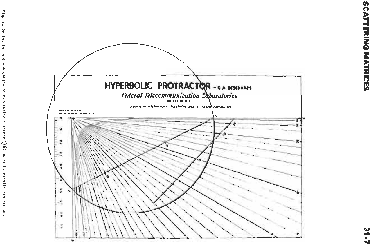
EVALUATION
OF
HYPERBOLIC
DISTANCE
On
the projective chart, the hyperbolic distance
<AB>
between two points
A
and
B
inside the circle
r
can be evaluated by means of a hyperbolic protractor as
shown in Fig.
8.
The line
AB
is extended to its
intersections
I
and
J
with
r.
The protractor is placed
so
that the sides
OX,
OY
of
the right angle go through
I
and
J.
(This can be done in many ways but does not affect
the result.) The numbers read on the radial lines
of
the
protractor going through
A
and
B,
respectively, are
added
if
A
and
B
are on opposite sides
of
the radial line
marked
0;
they are subtracted otherwise. This result
divided by 2 is the distance
<AB>.
In Fig.
8,
for
instance
<AB>
=
(12
+
4)
=
8
decibels
Problem
A
A
slotted line with 100-ohm characteristic imped-
ance is used to make measurements on a 60-ohm
SCATTERING
MATRICES
31-7
C*
:i
Fig.
8.
Definition
and
evaluation
of
hyperbolic distance
<AI@
using hyperbolic protractor.
31
-8
REFERENCE
DATA
FOR ENGINEERS
coaxial line. The transition acts
as
an ideal transformer.
Find the reflection coefficient
W
of an obstacle placed in
the coaxial line, knowing that it produces a reflection
coefficient
W'
=
0.5
exp
(jd2)
in the slotted line.
A
match in the coaxial line appears in the slotted line
as a normalized impedance
of
0.6; hence the mismatch
(standing-wave ratio in decibels) is 4.5 decibels. The
corresponding point
6'
is plotted
o_"
the projective chart
as in Fig.
9
at the distance
<OO'>
=
4.5. (On the
Smith chart drawn inside the same unit circle
r,
the
point would be
O'.)
The point
E'
representing the unknown load is
plotted at the hyperbolic distance
20
loglo[(l
+
0.5)/(1
-
OS)]
=
9.5
decibels
from the origin in the direction
+90".
The hyperbolic
distance
<o'w'>
=
11
decibels
is measured with the protractor. This is the mismatch
produced by the obstacle in the coaxial line. It corre-
sponds to a magnitude of the reflection coefficient of
0.56.
The phase
of
this reflection coefficient is the elliptic
angle
<o'P,D'w'>.
It is evaluated as explained in
Chapter 47: extend
QO'
up to
R
on
r
and measure the
arc
its properties may be found by the method described
earlier
in
this chapter. In particular, if the transition has
no losses (the circle
r
'
coincides with
r),
the point
0
'
may be found as in
(A),
(D),
(E),
or
(F),
above, the
point
P'
as in
(C)
or
(D),
above, and this completes the
calibration.
For any load placed in the waveguide and producing
the reflection coefficient
W'
in the slotted line, the
corrected standing-wave ratio in decibels is the hyper-
bolic distance
[O'W'].
This is evaluated by constructing
D',
w'
on the projective chart and measuring
<D'w'>
with the protractor. The phase angle is the elliptic angle
<o'P',D'w'>
(see Chapter 47).
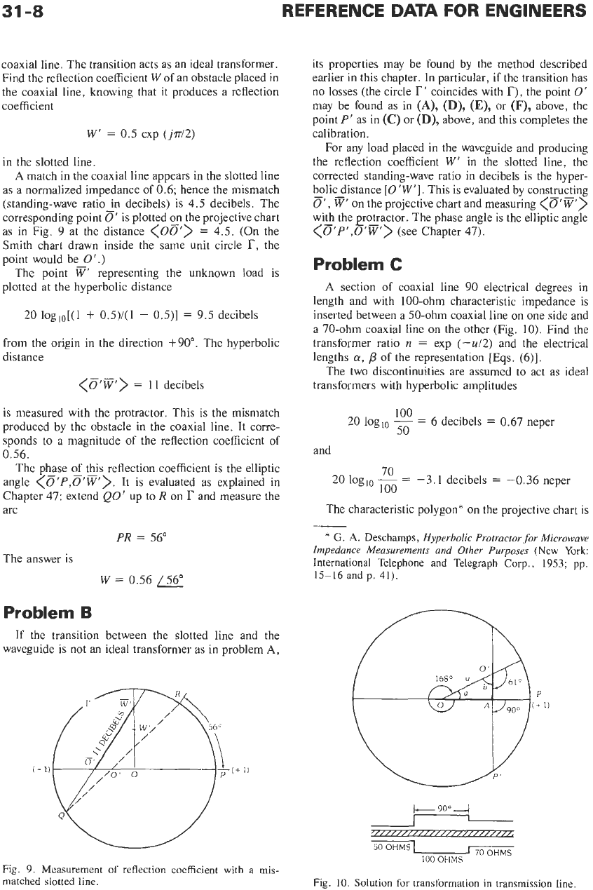
Problem C
A
section of coaxial line
90
electrical degrees in
length and with 100-ohm characteristic impedance is
inserted between a 50-ohm coaxial line
on
one side and
a 70-ohm coaxial line on the other (Fig.
10).
Find the
transformer ratio
n
=
exp
(-u/2)
and the electrical
lengths
a,
p
of the representation
[Eqs.
(6)].
The two discontinuities are assumed to act as ideal
transformers with hyperbolic amplitudes
100
50
20
loglo
-
=
6
decibels
=
0.67 neper
and
70
100
20
loglo
-
=
-3.1 decibels
=
-0.36 neper
The characteristic polygon* on the projective chart is
PR
=
56"
The answer is
W
=
0.56
/56"
Problem
B
If the transition between the slotted line and the
waveguide is not an ideal transformer as in problem
A,
Fig.
9.
Measurement
of
reflection coefficient with a mis-
matched slotted line.
*
G.
A.
Deschamps,
Hyperbolic Protractor for Microwave
Impedance Measurements and Other Purposes
(New York:
International Telephone and Telegraph
Corp.,
1953; pp.
15-16 and p.
41).
+
90"
-4
_I
/////////////////////////;
50
OHMS
I
70OHMS
100
OHMS
Fig.
10.
Solution for transformation in transmission line
SCATTERING MATRICES
31
-9
a triangle
OAO'
with right angle
A;
hence,
u
=
<OO'>
is given by
cosh
u
=
cosh
0.69
cosh
0.36
u
=
0.78
neper
=
6.8
decibels
n
=
exp
(-u/2)
=
111.48
The lengths of line
a
and
/3
can be deduced from
evaluating the elliptic angles
<OA,OO'>
=
a
and
<O'A,
O'O>
=
b
tan
a
=
tanh
0.36/sinh
0.69
=
0.46
a
=
24.7"
tan
b
=
tanh 0.69/sinh
0.36
=
1.62
b
=
58.4"
LY
=
i
(360"
-
24.7")
=
167.6'
/3
=
4
(180"
-
58.4")
=
60.8"
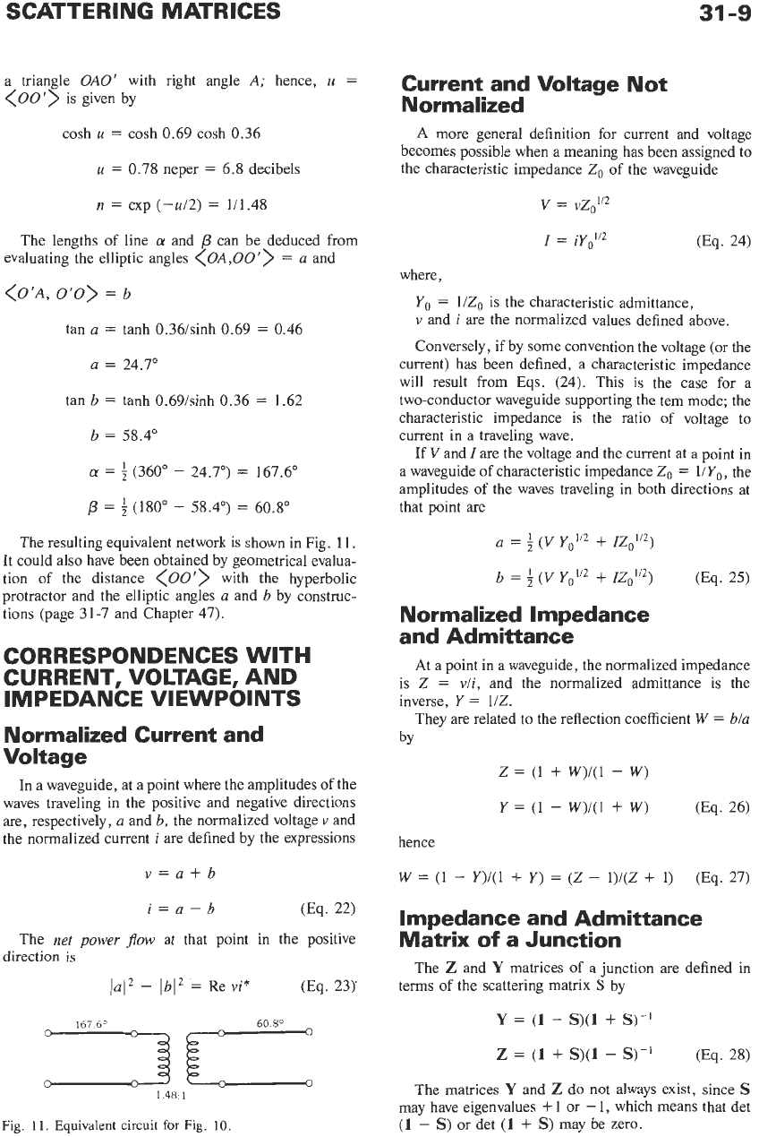
The resulting equivalent network is shown in Fig.
11.
It could also have been obtained by geometrical evalua-
tion of the distance
<OO'>
with the hyperbolic
protractor and the elliptic angles
a
and
b
by construc-
tions (page
31-7
and Chapter
47).
CORRESPONDENCES WITH
CURRENT, VOLTAGE, AND
IMPEDANCE VIEWPOINTS
Normalized Current and
Voltage
In
a waveguide, at a point where the amplitudes of the
waves traveling in the positive and negative directions
are, respectively,
a
and
b,
the normalized voltage
v
and
the normalized current
i
are defined by the expressions
v=a+b
i=a-b
(Eq.
22)
The
net
power
$ow
at that point in the positive
(Eq.
23)'
direction
is
lai2
-
lbI2
=
Re
vi*
..L
1
48
1
Fig.
11.
Equivalent circuit
for
Fig.
10.
Current and Voltage Not
Normalized
A
more general definition for current and voltage
becomes possible when a meaning has been assigned to
the characteristic impedance
Z,
of
the waveguide
V
=
vZo"2
I
=
iyo"2
0%.
24)
where,
Yo
=
l/Z,
is the characteristic admittance,
v
and
i
are the normalized values defined above.
Conversely, if by some convention the voltage (or the
current) has been defined, a characteristic impedance
will result from Eqs.
(24).
This is the case for a
two-conductor waveguide supporting the tern mode; the
characteristic impedance is the ratio of voltage to
current in a traveling wave.
If
V
and
I
are the voltage and the current at a point in
a waveguide of characteristic impedance
Zo
=
l/Yo,
the
amplitudes of the waves traveling in both directions at
that point are
a
=
4
(V
Y,'"
+
IZoi'2)
b
=
i
(V
+
IZoi12)
(Eq.
25)
Normalized Impedance
and Admittance
At
a point in a waveguide, the normalized impedance
is
Z
=
v/i,
and the normalized admittance is the
inverse,
Y
=
1/Z.
They are related to the reflection coefficient
W
=
b/a
by
z
=
(1
+
W)/(1
-
W)
Y
=
(1
-
W)/(1
+
W)
0%.
26)
hence
W
=
(1
-
Y)/(1
+
Y)
=
(Z
-
1)/(Z
+
1)
(Eq.
27)
Impedance and Admittance
Matrix
of
a Junction
The
Z
and
Y
matrices of a junction are defined in
terms
of
the scattering matrix
S
by
Y
=
(1
-
S)(1
+
s)-I
Z
=
(1
+
S)(1
-
S)-'
(Eq. 28)
The matrices
Y
and
Z
do
not
always exist, since
s
may have eigenvalues
+
1
or
-
1,
which means that det
(1
-
S)
or det
(1
+
S)
may be zero.