Middleton W.M. (ed.) Reference Data for Engineers: Radio, Electronics, Computer and Communications
Подождите немного. Документ загружается.

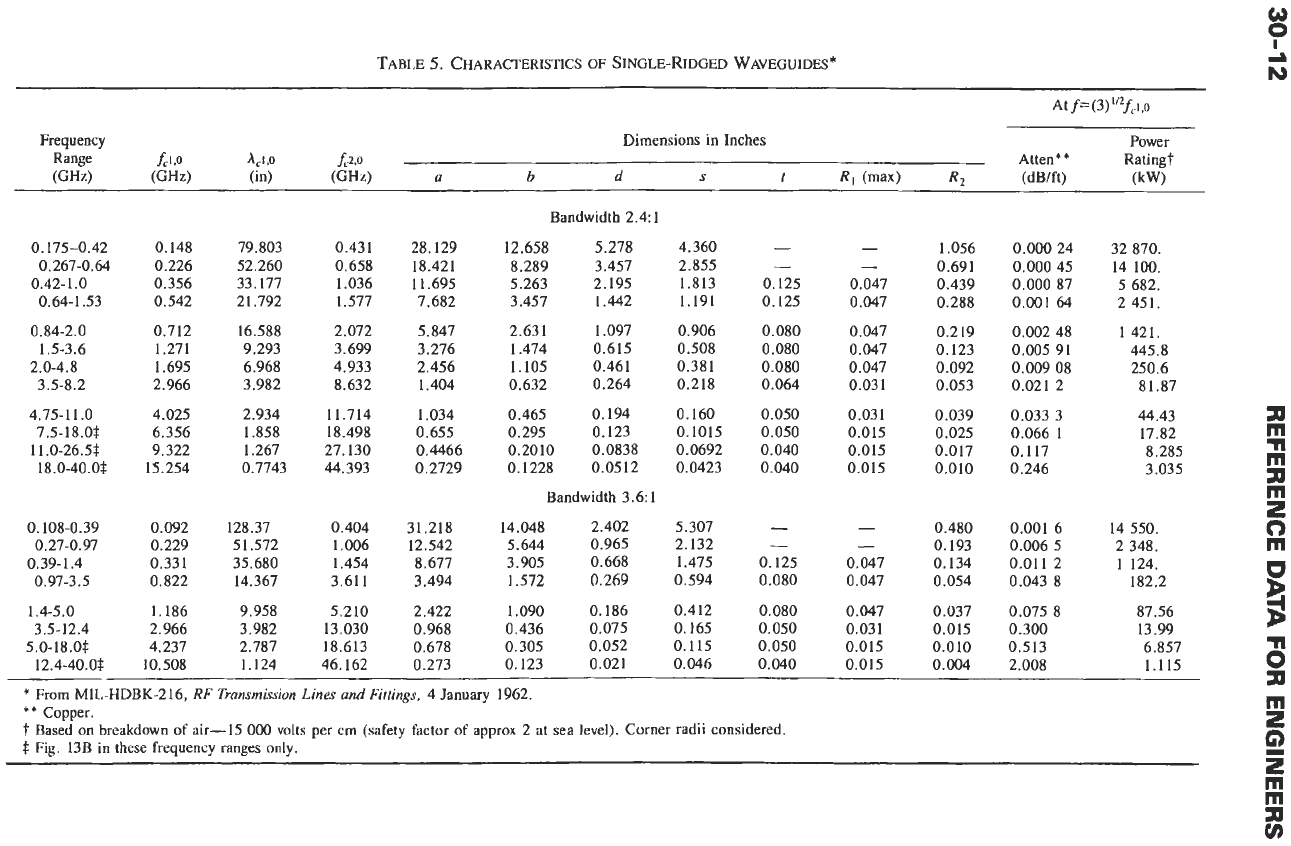
TABLE
5.
CHARACTERISTICS
OF
SINGLE-RIDGED
WAVEGUIDES
*
At f=(3)''?fCi,o
power
Dimensions in Inches
0.175-0.42
0.267-0.64
0.42-1
.O
0.64-1.53
0.84-2.0
1.5-3.6
2.0-4.8
3.5-8.2
4.75-1
1
.O
7.5-18.0s
11.0-26.5s
18.0-40.0$
0.108-0.39
0.27-0.97
0.39-1.4
0.97-3.5
1.4-5.0
3.5-12.4
5.0-18.0s
12.4-40.0$
0.148
0.226
0.356
0.542
0.712
1.271
1.695
2.966
4.025
6.356
9.322
15.254
0.092
0.229
0.331
0.822
1.186
2.966
4.237
10.508
79.803
52.260
33.177
21.792
16.588
9.293
6.968
3.982
2.934
1.858
1.267
0.7743
128.37
51.572
35.680
14.367
9.958
3.982
2.787
0.431
0.658
1.036
1.577
2.072
3.699
4.933
8.632
11.714
18.498
27.130
44.393
0.404
1.006
1.454
3.611
5.210
13.030
18.613
1.124 46.162
28.129
18.421
11.695
7.682
5.847
3.276
2.456
1.404
1.034
0.655
0.4466
0.2729
31.218
12.542
8.677
3.494
2.422
0.968
0.678
0.273
Bandwidth
2.41
12.658 5.278
8.289 3.457
5.263 2.195
3.457 1.442
2.631 1.097
1.474 0.615
1.105 0.461
0.632 0.264
0.465 0.194
0.295 0.123
0.2010 0.0838
0.1228 0.0512
Bandwidth 3.6:
1
14.048 2.402
5.644 0.965
3.905 0.668
1.572
0,269
1.090 0.186
0,436 0.075
0.305 0.052
0.123 0.021
4.360
2.855
1.813
1.191
0.906
0.508
0.381
0.218
0.160
0.1015
0.0692
0.0423
5.307
2.132
1.475
0.594
0.412
0.165
0.115
0.046
-
-
0.125
0.125
0.080
0.080
0.080
0.064
0.050
0.050
0.040
0.040
-
-
0.125
0.080
0.080
0.050
0.050
0.040
-
-
0.047
0.047
0.047
0.047
0.047
0.031
0.031
0.015
0.015
0.015
-
-
0.047
0.047
0.047
0.031
0.015
0.015
1.056
0.691
0.439
0.288
0.219
0.123
0.092
0.053
0.039
0.025
0.017
0.010
0.480
0.193
0.134
0.054
0.037
0.015
0.010
0.004
0.000 24
0.000
45
0.000
87
0.001
64
0.002
48
0.005 91
0.009 08
0.021
2
0.033 3
0.066
1
0.117
0.246
0.001 6
0.006 5
0.011 2
0.043 8
0.075 8
0.300
0.513
2.008
32 870.
14 100.
5
682.
2 451.
1421.
445.8
250.6
81.87
44.43
17.82
8.285
3.035
14 550.
2 348.
1
124.
182.2
87.56
13.99
6.857
1.115
~~~~ ~
*
From
MIL-HDBK-216,
RF
Transmission
Lines
and
Fittings,
4
January
1962.
**
Copper.
'f
Based on breakdown of air-15
000
volts per
crn
(safety factor
of
approx 2 at sea level). Corner radii considered.
$
Fig.
13B
in
these frequency
ranges
only.
0
0
h)
I
d
a
m
n
m
a
m
2
c)
m
U
B
6
3p
m
2
G)
m
m
3p
v)
z
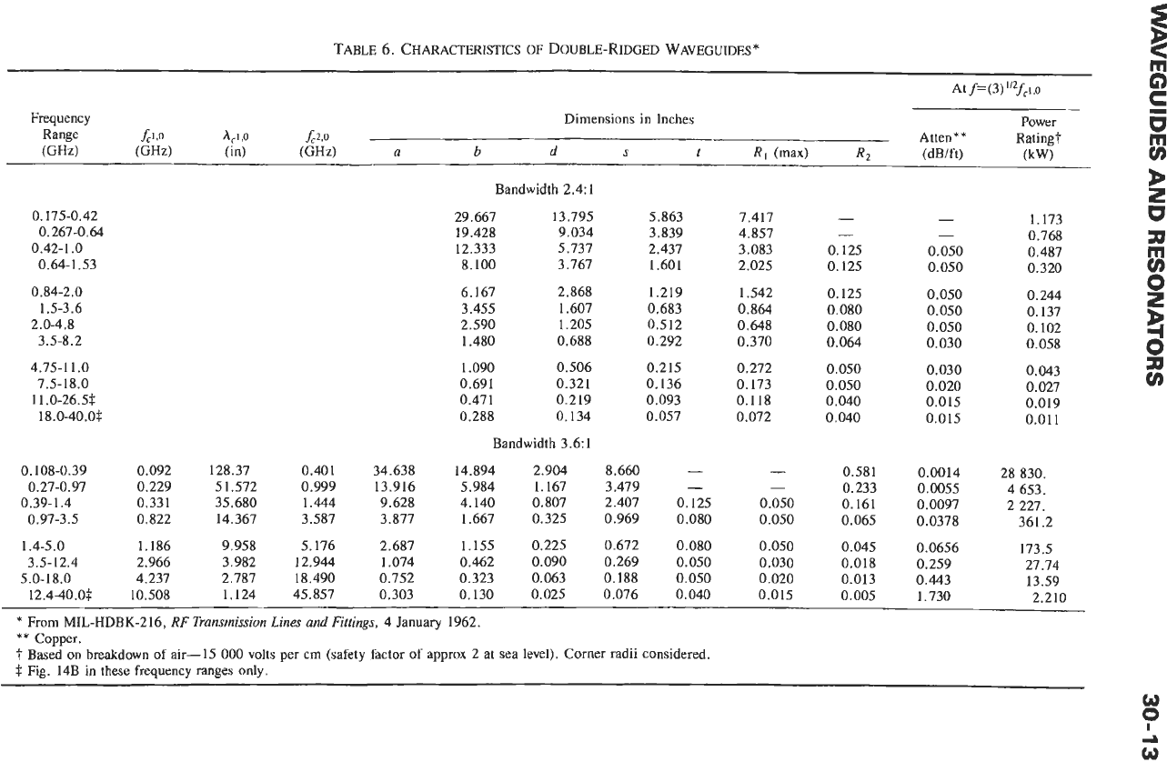
TABLE
6.
CHARACTERISTICS
OF
DOUBLE-RIDGED
WAVEOUIDES*
0.175-0.42
0.267-0.64
0.42-1
.O
0.64-1.53
0.84-2.0
1.5-3.6
2.0-4.8
3.5-8.2
4.75-1 1
.O
7.5- 18
.O
11.0-26.5$
18.0-40.0$
0.108-0.39
0.27-0.97
0.39-1.4
0.97-3.5
1.4-5.0
3.5-12.4
5.0-18.0
0.092
0.229
0.331
0.822
1.186
2.966
4.237
10.508
128.37
51.572
35.680
14.367
9.958
3.982
2.787
1.124
0.401
0.999
1.444
3.587
5.176
12.944
18.490
45.857
34.638
13.916
9.628
3.877
2.687
1.074
0.752
0.303
Bandwidth
2.4:
1
29.667 13.795
5.863
19.428 9.034 3.839
12.333 5.737 2.437
8.100 3.767 1.601
6.167 2.868
1.219
3.455 1.607 0.683
2.590 1.205
0.512
1.480
0.688 0.292
1.090 0.506
0.215
0.691
0.321 0.136
0.471 0.219
0.093
0.288
0.134 0.057
Bandwidth
3.6:1
14.894 2.904
8.660
-
5.984 1.167
3.479
-
4.140 0.807 2.407 0.125
1.667 0.325
0.969 0.080
1.155
0.225 0.672 0.080
0.462
0.090 0.269 0.050
0.323 0.063
0.188
0.050
0.130
0.025 0.076
0.040
7.417
4.857
3.083
2.025
1.542
0.864
0.648
0.370
0.272
0.173
0.118
0.072
-
-
0.050
0.050
0.050
0.030
0.020
0.015
-
-
0.125
0.125
0.125
0.080
0.080
0.064
0.050
0.050
0.040
0.040
0.581
0.233
0.161
0.065
0.045
0.018
0.013
0.005
-
-
0.050
0.050
0.050
0.050
0.050
0.030
0.030
0.020
0.015
0.015
0.0014
0.0055
0.0097
0.0378
0.0656
0.259
0.443
1.730
P
z
1.173
W
0.768
a
0.487
0.320
0.244
0.137
0.102
0
z
0.058
d
3
v)
0.043
0.027
0.019
0.011
28 830.
4 653.
2 227.
361.2
173.5
27.74
13.59
2.210
12.4-40.0.t
I
*
From
MIL-HDBK-216.
RF
Transmission
Lines
and
FlIIinns,
4
January
1962.
* *
Copper.
'f
Based
on
breakdown
of
air-15
000
volts per cm (safety factor of approx
2
at sea level). Corner radii considered.
.t
Fig.
14B
in
these frequency
ranges
only.
w
0
0
I
d
30-14
REFERENCE
DATA
FOR ENGINEERS
twist, and straight section of a long waveguide run
between fixed points, it is often adequate to leave a
short run or bend to be filled by a flexible guide insert.
Flexible sections
are
also used to permit thermally
induced relative movement and to insulate portions
of
a
waveguide run from shock and vibration. Flexible
waveguide should not be treated as a link between a
cabinet and its frequently opened doors and drawers,
unless the cabinet is specified and/or designed for that
type
of
service. Most flexible-waveguide structures are
susceptible
to
cracking under these conditions if flexure
is
repeated often.
Flexible waveguide is available in many different
forms. It may be made from flat ribbons wound on a
rectangular mandrel with the edges convoluted or folded
in and interlocked. The convoluted guide may be
soldered or unsoldered, since the bending and twisting
results from a flexure of each turn and not from a
relative sliding as in the case of the interlocked guide. If
soldered, it is more difficult to flex and essentially loses
twist capability.
Corrugated flexible guide may be made by properly
shaping thin-wall seamless rectangular tubing, or by
bending and soldering corrugated sheet metal (with due
consideration to current flow
so
that a low-loss joint
results).
A
bellows-type guide is produced from a group of
radial chokes in tandem configuration and made of a
flexible alloy.
Vertebral guide is made from a tandem chain of
choke-cover sections contained within a neoprene or
rubber jacket.
In
general, all types except the seamless corrugated
waveguide should be jacketed with neoprene or rubber.
The unsoldered convoluted, interlocking, and vertebral
guide must be jacketed to be pressurized.
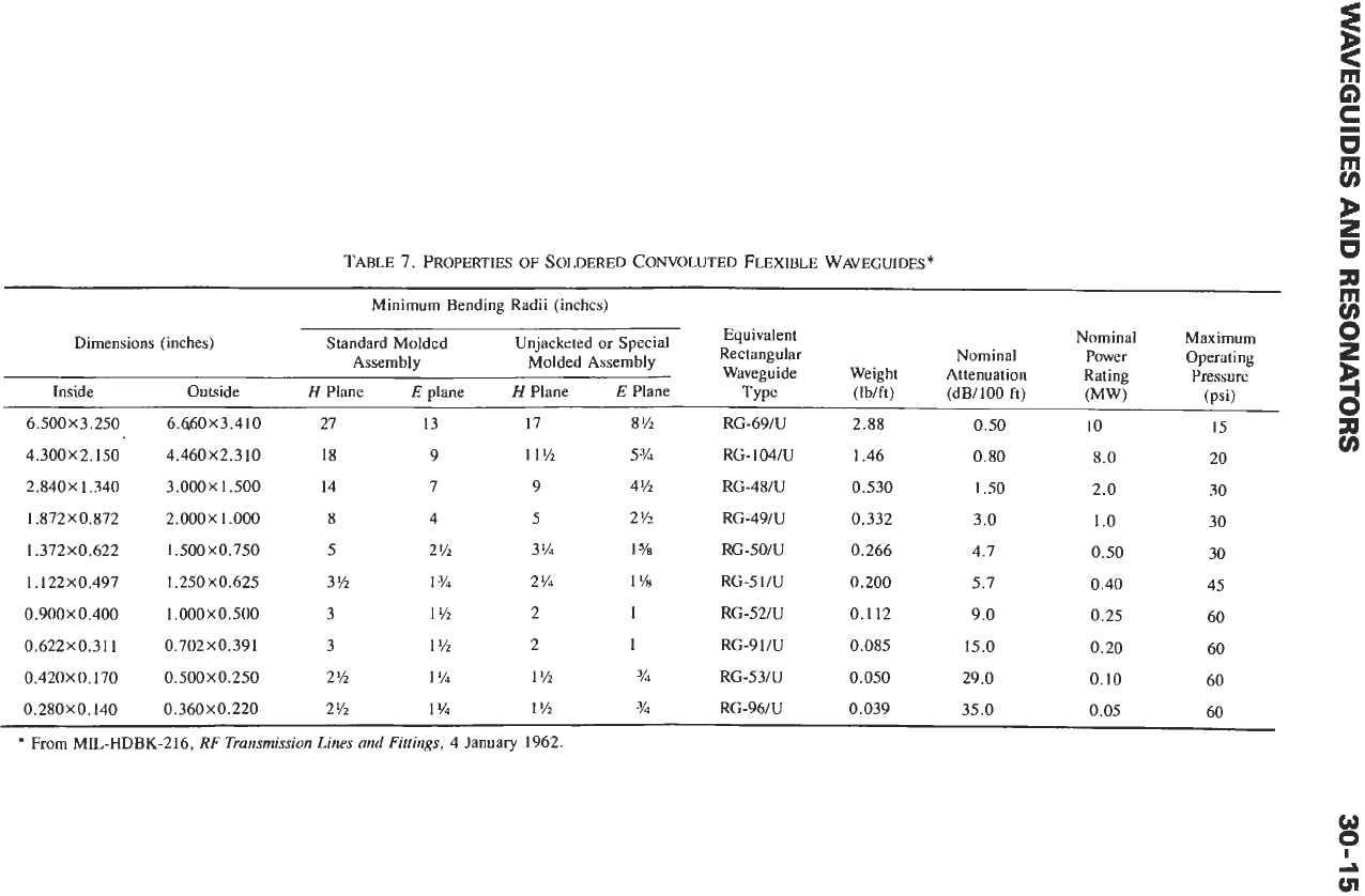
Table
7
gives the properties of soldered convoluted
flexible waveguide.
The wide variety of manufacturing techniques, the
jacketing material and thickness, the length depen-
dence, and other characteristics make it impossible to
limit the
(e)
stretch, twist, and center-line displace-
ment ranges of flexible waveguide. These are usually
described in terms of maximum acceptable vswr or
loss
of the section as a function of the
(C)
stretch, twist, or
displacement, and are best established on advice from
the manufacturer selected.
WAVEGUIDE
LOSSES
Hollow, enclosed single-conductor waveguides,
propagating in the interior space, exhibit losses via
dissipation in the waveguide walls and the dielectric
material filling the space, leakage through the walls and
connections to the guide, and localized power absorp-
tion (and heating) at the connections (flanges) because
of poor contact or fabrication. The following discussion
assumes that the dielectric is air, with zero loss tangent,
and that the depth of penetration into the walls is very
much less than the wall thickness,
so
that no apprecia-
ble wall leakage occurs.
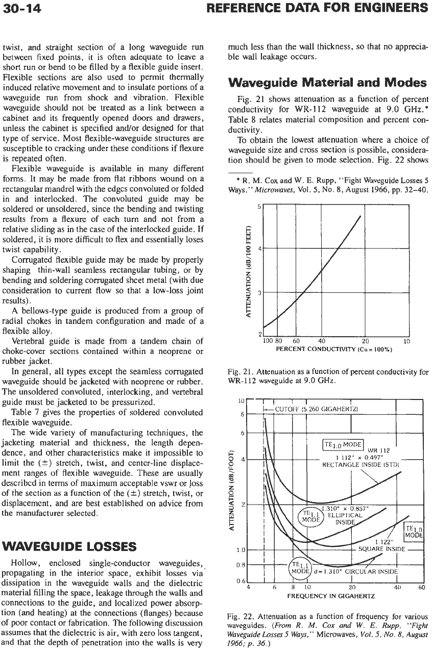
Waveguide Material and Modes
Fig.
21
shows attenuation as a function of percent
conductivity for
WR-112
waveguide at
9.0
GHz.*
Table
8
relates material composition and percent con-
ductivity.
To obtain the lowest attenuation where a choice of
waveguide size and cross section is possible, considera-
tion should be given to mode selection. Fig.
22
shows
*
R.
M.
Cox
and
W.
E.
Rupp,
“Fight Waveguide
Losses
5
Ways.”
Microwaves,
Vol.
5,
No.
8,
August 1966,
pp.
32-40.
~~
PERCENT CONDUCTIVITY (Cu
=
100%)
Fig.
21.
Attenuation
as
a
function
of
percent conductivity
for
WR-112 waveguide
at
9.0
GHz.
FREQUENCY IN GIGAHERTZ
Fig. 22.
Attenuation
as
a
function
of
frequency
for
various
waveguides.
(From
R.
M.
Cox
and
W.
E.
Rupp,
“Fight
Waveguidehsses
5
Ways,”
Microwaves,
Vol.
5,
No.
8,
August
1966;
p.
36.)
z
@
s
5
w
c
b
2
U
z
m
TABLE
7.
PROPERTIES
OF
SOLDERED CONVOLUTED FLEXIBLE WAVEGUIDES
*
Minimum Bending Radii (inches)
Uimensions (incnes) btanaara
Moiaea
C
Assembly
a
Inside Outside
H
Plane
E
plane
H
Plane
E
Plane
Type
(Ib/ft) (dB/100
ft)
(psi)
6.500
X
3.250 6.660
X
3.410 27 13
17
8% RG-69/U 2.88 0.50
10
15
z
v)
4.300X 2.150
4.460X2.3
10
18
9
11% 5
3/4
RG- 104/U 1.46
0.80 8.0 20
2.840X1.340
3.000X1.500
14
7
9
4
Y2
RG-48/U
0.530
1.50 2.0 30
1.872X0.872
2.000X1.000
8 4 5 2
Y2
RG-49/U 0.332
3.0 1
.o
30
1.372X0.622
1.500X0.750
5 2%
3% 1
vi7
RG-SO/U
0.266
4.7 0.50 30
1.122
x
0.497
1.250
x
0.625
3%
1
3/4
2%
1
'/a
RG-5
1/U
0.200
5.7 0.40 45
0.900
X
0.400
1
,000
X
0.500 3 1% 2
1
RG-52N 0.112
9.0
0.25 60
0.622x0.311 0.702x0.391 3
1
Y2
2
1
RG-9 1/U 0.085 15.0 0.20 60
0.420
X
0.170
0.500
X
0.250 2%
1
'/4
1
'/2
Y4
RG-53/U 0.050 29.0
0.10
60
0.280x0.140 0.360x0.220 2%
1%
1%
%I
RG-96/U 0.039 35.0 0.05 60
*
From MIL-HDBK-216,
RF
Transmission Lines and Fittings,
4 January 1962.
30-16
REFERENCE
DATA
FOR ENGINEERS
TABLE
8.
COMPOSITION
AND
CONDUCTIVITY
OF
WAVEGUIDE
MATERIAL*
Composition
(%)
%
Material cu Zn
P
Ag AI Mg Conductivity”*
Copper (oxygen free)
99.95t
-
-
-
- -
97.6 min
Copper DLP (deoxidized,
99.90f
-
0.004-
-
-
-
96.1 min
Commercial Bronze
89-91
9-11
-
- - -
44.2 min
100.0
min
Silver (fine) 0.08 max
-
Coin Silver
9-10.4
0.06
-
89.6-91.0
-
-
82.0 min
Aluminum 1100
0.2
0.10
- -
99.0 min
-
59.5 min
Aluminum 606 1 0.15-0.40
0.25
-
-
95 0.8-1.2 40.0 min
min
low phosphorus) min 0.012
-
-
99.90
-
rnin
Magnesium
-
0.05 0.6-1.4
-
2.5-3.5 94.0 37.58
*
From R. M.
Cox
and W.
E.
Rupp, “Fight Waveguide Losses 5 Ways,”
Microwaves,
Vol.
5,
No.
8,
August 1966,
p.
34.
**
International Annealed Copper Standard.
i
Any silver present is counted
in
the copper content.
$
MIL-HDBK-216, Military Standardization Handbook,
RF Transmission Lines and Fittings,
4 January 1962.
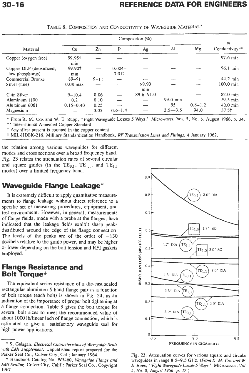
the relation among various waveguides for different
modes and
cross
sections over a broad frequency band.
Fig.
23
relates the attenuation rates of several circular
and square guides (in the TEo,l, TEI,I, and TEl,o
modes) over a limited frequency band.
Waveguide Flange Leakage”
It is extremely difficult to apply quantitative measure-
ments to flange leakage without direct reference to a
specific set of measuring procedures, equipment, and
test environment. However, in general, measurements
of
flange fields, made with a probe at the flanges, have
indicated that the leakage fields exhibit sharp peaks
distributed around the edge of the flange connection.
The levels of the peaks are of the order of
-130
decibels relative to the guide power, and may be higher
or lower depending on the bolt tension and
RFI
gaskets
employed.
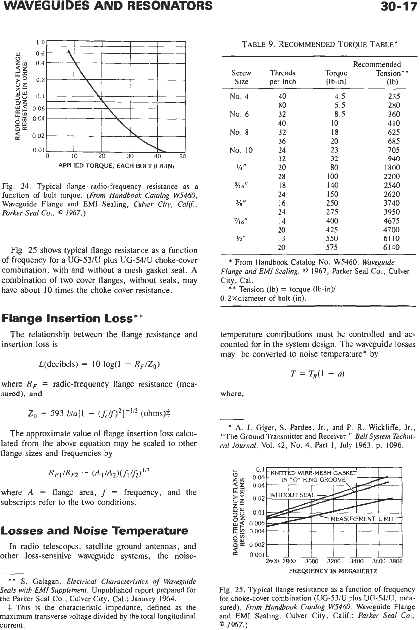
Flange Resistance and
Bolt Torque?
The equivalent series resistance
of
a die-cast sealed
rectangular aluminum S-band flange pair as a function
of bolt
torque
(each bolt)
is
shown
in
Fig.
24,
as
an
indication
of
the importance
of
proper bolt tightening at
a flange connection. Table
9
gives the bolt torque for
several bolt sizes to meet the recommended value of
about
1000
lb/linear inch of flange connection, which is
estimated to give a satisfactory waveguide seal for
high-power applications.
*
S
. Galagan.
Electrical Characteristics
of
Waveguide Seals
with
EM1
Supplement.
Unpublished report prepared
for
the
Parker Seal Co., Culver City, Cal.; January 1964.
f
Handbook Catalog
No.
W5460,
Waveguide Flange and
EM1
Sealing,
Culver City, Calif.: Parker Seal Co., Copyright
1967.
0.7
-
01
85
90
9
FREQUENCY
IN
GIGAHERTZ
Fig. 23. Attenuation curves for various square and circular
waveguides in range 8.5-9.5 GHz.
(From
R.
M.
Cox
and W.
E.
Rupp, “Fight Waveguide Losses
5
Ways,”
Microwaves, Vol.
5,
No.
8,
August
1966;
p.
37.)
WAVEGUIDES AND RESONATORS
30-17
10
06
04
02
01
0 06
0
04
0 02
0 01
0 10 20
30
40
50
APPLIED
TORQUE,
EACH
BOLT
(LB-IN)
Fig.
24.
Typical flange radio-frequency resistance as a
function
of
bolt torque.
(From Handbook Catalog W5460,
Waveguide Flange and
EM1
Sealing,
Culver City, Calif.:
Parker Seal Co.,
@
1967.)
Fig.
25
shows typical flange resistance as a function
of frequency for a UG-53/U plus UG-54/U choke-cover
combination, with and without a mesh gasket seal.
A
combination of two cover flanges, without seals, may
have about
10
times the choke-cover resistance.
Flange Insertion
Loss**
The relationship between the flange resistance and
insertion loss is
L(decibe1s)
=
10
log(1
-
RF/Zo)
where
RF
=
radio-frequency flange resistance (mea-
sured), and
Z,
=
593
b/a[l
-
(fC/f)*]-”’
(ohms)$
The approximate value
of
flange insertion loss calcu-
lated from the above equation may be scaled to other
flange sizes and frequencies by
RFIlRF2
-
(A,/A*)(h/f2)1’2
where
A
=
flange area,
f
=
frequency, and the
subscripts refer to the two conditions.
Losses
and
Noise Temperature
In radio telescopes, satellite ground antennas, and
other loss-sensitive waveguide systems, the noise-
*
*
S
.
Galagan.
Electrical Characteristics
of
Waveguide
Seals with
EMZ
Supplement.
Unpublished report prepared for
the Parker Seal Co., Culver City, Cal.; January
1964.
$
This is the characteristic impedance, defined as the
maximum
transverse voltage divided by the total longitudinal
current.
TABLE
9.
RECOMMENDED
TORQUE TABLE*
Recommended
Size per Inch (lb-in) (1b)
Torque Tension*
*
Screw Threads
No.
4 40
80
No.
6 32
40
No.
8 32
36
No.
10 24
32
vin
20
28
716’’
18
24
%”
16
24
7/16”
14
20
Y2“
13
20
4.5
5.5
8.5
10
18
20
23
32
80
100
140
150
250
275
400
425
550
575
235
280
360
410
625
685
705
940
1800
2200
2540
2620
3740
3950
4675
4700
61
10
6140
*
From Handbook Catalog
No.
W5460,
Waveguide
Flange and
EMI
Sealing.
0
1967,
Parker Seal Co., Culvex
City, Cal.
0.2Xdiameter of bolt (in).
**
Tension (lb)
=
torque (lb-in)/
temperature contributions must be controlled and ac-
counted for in the system design. The waveguide losses
may be converted
to
noise temperature* by
T
=
TR(1
-
a)
where,
-
*
A.
I.
Ciger,
S.
Pardee, Jr., and P. R. Wickliffe, Jr.,
“The Ground Transmitter and Receiver.”
Bell System Techni-
cal Journal,
Vol.
42,
NO.
4,
Part
1,
July
1963,
p.
1096.
01
0
06
0 04
0 02
0 01
0 006
0
004
0 002
0.0Ol~I
2600 2800 3000 3200 3400 3600 3800
FREQUENCY
IN
MEGAHERTZ
Fig.
25.
Typical flange resistance as a function of frequency
for choke-cover combination
(UG-53/U
plus
UG-54/U,
mea-
sured).
From Handbook Catalog W5460,
Waveguide Flange
and
EM1
Sealing, Culver City, Calif.:
Parker Seal Co.,
0
1967.)
30-18
REFERENCE
DATA
FOR ENGINEERS
1000
m
z
y
100
z
2
W
z
3
2
10
B
5
PI
+
10
W
8
01
100
10 10
01
0010001
INSERTION
LOSS
IN
DECIBELS
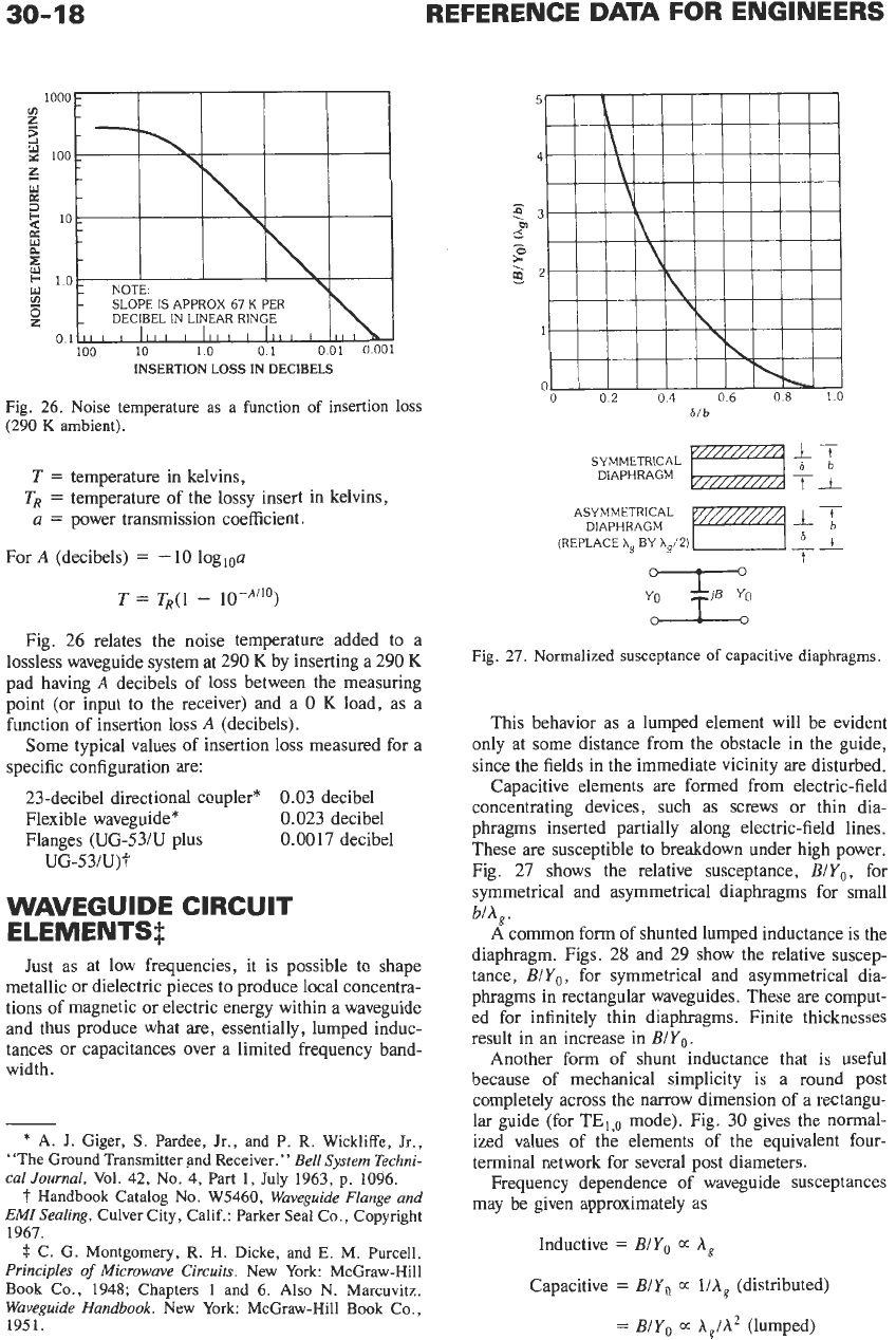
Fig. 26. Noise temperature as a function of insertion loss
(290
K
ambient).
T
=
temperature in kelvins,
a
=
power transmission coefficient.
TR
=
temperature of the lossy insert in kelvins,
For
A
(decibels)
=
-
10
logloa
T
=
T,(1
-
10-A”O)
Fig. 26 relates the noise temperature added to a
lossless waveguide system at 290
K
by inserting a 290
K
pad having
A
decibels of loss between the measuring
point (or input to the receiver) and a
0
K
load, as a
function of insertion loss
A
(decibels).
Some typical values of insertion loss measured for a
specific configuration are:
23-decibel directional coupler* 0.03 decibel
Flexible waveguide* 0.023 decibel
Flanges (UG-53/U plus 0.0017 decibel
UG-53/U)S
WAVEGUIDE CIRCUIT
ELEMENTS$
Just as at low frequencies, it is possible to shape
metallic or dielectric pieces to produce local concentra-
tions of magnetic or electric energy within a waveguide
and thus produce what are, essentially, lumped induc-
tances or capacitances over a limited frequency band-
width.
-
*
A.
J.
Giger,
S.
Pardee, Jr., and
P.
R. Wickliffe,
Jr.,
“The Ground Transmitter and Receiver.
”
Bell
System
Techni-
cal Journal,
Vol. 42, No.
4,
Part
1,
July 1963, p. 1096.
t
Handbook Catalog No. W5460,
Waveguide Flange and
EMI Sealing,
Culver City, Calif.: Parker Seal Co., Copyright
1967.
#
C. G. Montgomery, R.
H.
Dicke, and
E.
M.
Purcell.
Principles
of
Microwave Circuits.
New York: McGraw-Hill
Book Co., 1948; Chapters
1
and 6.
Also
N. Marcuvitz.
Waveguide Handbook.
New York: McGraw-Hill Book Co.,
1951.
0
02
04
06 08
10
6/b
17
ti
6b
SYMMETRICAL
DIAPHRAGM
-
ASYMMETRICAL
DIAPHRAGM
(REPLACE
Xg
BY
X,/2)
__
6t
+
.,.F;
Fig. 27. Normalized susceptance
of
capacitive diaphragms.
This behavior as a lumped element will be evident
only at some distance from the obstacle in the guide,
since the fields in the immediate vicinity are disturbed.
Capacitive elements are formed from electric-field
concentrating devices, such as screws or thin dia-
phragms inserted partially along electric-field lines.
These are susceptible to breakdown under high power.
Fig. 27 shows the relative susceptance,
B/Yo,
for
symmetrical and asymmetrical diaphragms for small
b/A,.
A
common form of shunted lumped inductance is the
diaphragm. Figs. 28 and 29 show the relative suscep-
tance,
B/Yo,
for symmetrical and asymmetrical dia-
phragms in rectangular waveguides. These are comput-
ed for infinitely thin diaphragms. Finite thicknesses
result in an increase in
BIY,.
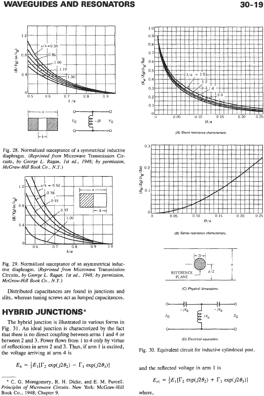
Another form of shunt inductance that is useful
because of mechanical simplicity is a round post
completely across the narrow dimension of a rectangu-
lar guide (for
TE,,,
mode). Fig. 30 gives the normal-
ized values of the elements of the equivalent four-
terminal network for several post diameters.
Frequency dependence of waveguide susceptances
may be given approximately as
Inductive
=
B/Yo
E
A,
Capacitive
=
B/Yo
E
liA,
(distributed)
=
B/Yo
E
A,lA2
(lumped)
WAVEGUIDES AND RESONATORS
30-
19
IIIIIIIIII
I"1
"
Fig.
28.
Normalized susceptance
of
a symmetrical inductive
diaphragm.
(Reprinted from
Microwave Transmission Cir-
cuits,
by
George
L.
Ragan, 1st ed.,
1948;
by
permission,
McGraw-Hill
Book
Co.,
N.Y.)
12
e
F
0
08
-
9
04
0
06
07 08 09 10
6/a
Fig.
29.
Normalized susceptance
of
an asymmetrical induc-
tive diaphragm.
(Reprinted from
Microwave Transmission
Circuits,
by
George
L.
Ragan, 1st ed.,
1948;
by
permission,
McGraw-Hill
Book
Co.,
N.Y.)
Distributed capacitances
are
found in junctions and
slits, whereas tuning screws act as lumped capacitances.
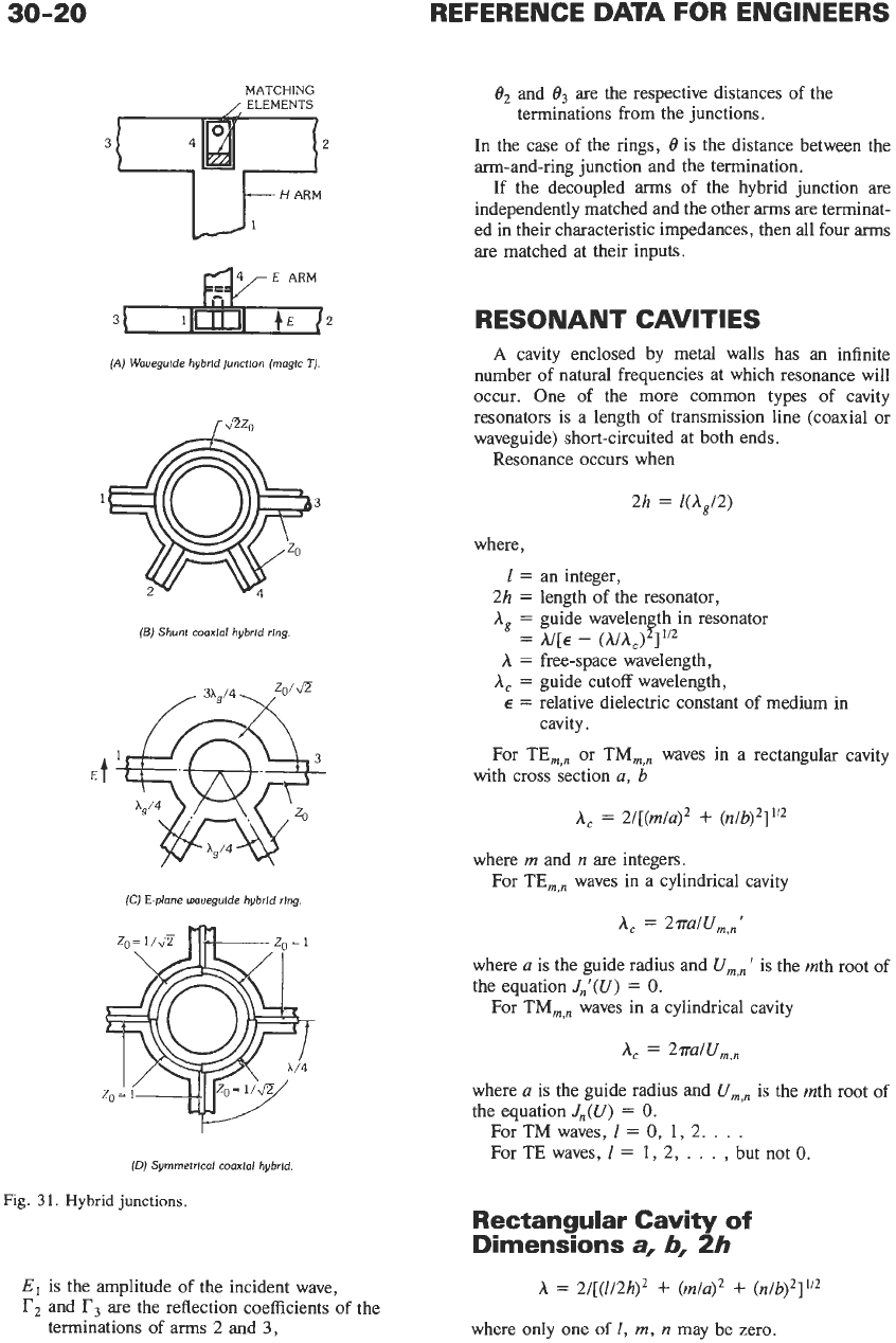
HYBRID JUNCTIONS*
The hybrid junction is illustrated
in
various forms in
Fig.
3
1.
An
ideal junction is characterized
by
the fact
that
there
is
no direct coupling between
arms
1
and
4
or
between 2 and
3.
Power flows from
1
to
4
only by virtue
of reflections
in
arms
2 and
3.
Thus, if
arm
1
is excited,
the
voltage arriving at
arm
4
is
*
C. G. Montgomery,
R.
H. Dicke, and
E.
M. Purcell.
Principles of Microwave Circuits.
New York: McGraw-Hill
Book Co.,
1948;
Chapter
9.
0
0
20 025
0
05
0 10 0
15
Dla
(AI
Shunt reactance characterlstlc.
03
ii
02
?
2
T
go1
0
0
0
05
0
10
0
15
020 025
Dla
(6)
Series reactance eharacteristrc
REFERENCE
2
d/2
PLANE
I
I
(C)
Physlcal
dlrnenslons
1
-
(D)
Electrlcal equlualent.
Fig.
30.
Equivalent
circuit
for
inductive cylindrical post.
30-20
REFERENCE DATA FOR ENGINEERS
MATCHING
/
ELEMENTS
u-””””
(A)
Waveguide hybrld Junctlon (maglc
7).
(5)
Shunt
coaxial
hybrld rlng.
(C)
E-plane
wnvegulde hybrld rlng.
(0)
Symrnetrlcnl
conxlal
hybrld.
Fig.
31.
Hybrid
junctions.
E,
is the amplitude
of
the incident wave,
r2
and
r3
are
the reflection coefficients
of
the
terminations of
arms
2
and
3,
f12
and
O3
are the respective distances
of
the
terminations from the junctions.
In the case
of
the rings,
6
is the distance between the
arm-and-ring junction and the termination.
If
the decoupled
arms
of
the hybrid junction are
independently matched and the other
arms
are terminat-
ed in their characteristic impedances, then all four
arms
are matched at their inputs.
RESONANT CAVITIES
A
cavity enclosed by metal walls has an infinite
number
of
natural frequencies at which resonance will
occur. One
of
the more common types of cavity
resonators is a length
of
transmission line (coaxial or
waveguide) short-circuited at both ends.
Resonance occurs when
2h
=
l(A,/2)
where,
1
=
an integer,
2h
=
length of the resonator,
A,
=
guide wavelen th in resonator
=
A/[€
-
(MA,)
B
1”’
A
=
free-space wavelength,
A,
=
guide cutoff wavelength,
E
=
relative dielectric constant
of
medium in
cavity.
with cross section
a,
b
For TE,,, or
TM,,,
waves in a rectangular cavity
A,
=
Z/[(~/U)~
+
(n/b)2]”2
where
m
and
n
are integers.
For TE,,, waves in a cylindrical cavity
A,
=
2ra/Urn,,’
where
a
is the guide radius and
Urn,,
’
is the rnth root
of
the equation
J,’(U)
=
0.
For TM,,, waves in a cylindrical cavity
A,
=
2ra/U,,,
where
a
is the guide radius and
UmXn
is the rnth root of
the equation
J,(U)
=
0.
For TM waves,
I
=
0,
1,
2.
. . .
For TE waves,
I
=
1,
2,
. . .
,
but not
0.
Rectangular Cavity
of
Dimensions
a,
b,
2h
A
=
2/[(1/2h)’
+
(m/a)*
+
(n/b)*I1’*
where only one of
I,
m,
n
may be zero.
WAVEGUIDES AND RESONATORS
30-21
Cylindrical Cavities
of
Radius
a
and Length
2h
A
=
1/[(1/4h)*
+
(llAc)z]l’z
where
A,
is
the guide cutoff wavelength.
Spherical Resonators
of
Radius
a
A
=
2,~a/U,,~
for a TE wave
A
=
2~a/U,,~’
for a TM wave
Values of
Values of
I:
U1,l’
=
2.75
=
lowest-order root
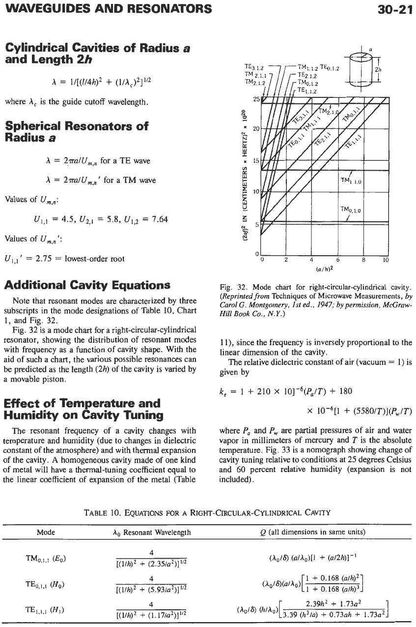
Additional Cavity Equations
Note that resonant modes are characterized by three
subscripts in the mode designations of Table
10,
Chart
1,
and Fig.
32.
Fig.
32
is a mode chart for a right-circular-cylindrical
resonator, showing the distribution of resonant modes
with frequency as a function of cavity shape. With the
aid of such a chart, the various possible resonances can
be predicted as the length
(2h)
of the cavity is varied by
a movable piston.
Effect
of
Temperature and
Humidity on Cavity Tuning
The resonant frequency of a cavity changes with
temperature and humidity (due to changes in dielectric
constant of the atmosphere) and with thermal expansion
of the cavity.
A
homogeneous cavity made of one kind
of metal will have a thermal-tuning coefficient equal to
the linear coefficient of expansion of the metal (Table
01
I
I
I
I
02
4
6 8
10
(alh)*
Fig.
32.
Mode chart
for
right-circular-cylindrical cavity.
(Reprinted
from
Techniques
of
Microwave Measurements,
by
Carol
G. Montgomery,
1st ed., 1947;
by
permission, McGraw-
Hill
Book
Co.,
N.Y.)
1 1)
,
since the frequency is inversely proportional to the
linear dimension of the cavity.
The relative dielectric constant of air (vacuum
=
1)
is
given by
k,
=
1
+
210
X
10]-6(P,/T)
+
180
X
10-6[1
+
(5580/T)](Pw/T)
where
P,
and
P,,,
are partial pressures of air and water
vapor in millimeters of mercury and
T
is the absolute
temperature. Fig.
33
is a nomograph showing change of
cavity tuning relative to conditions at
25
degrees Celsius
and
60
percent relative humidity (expansion is not
included).
TABLE
10.
EQUATIONS
FOR
A
RIGHT-CIRCULAR-CYLINDRICAL CAVITY
Mode
ho
Resonant Wavelength
Q
(all dimensions in same units)
(Ao/@
(a/ho)[l
+
(u/2h)]-’
1
1
+
0.168
(c~lh)~
(A0/S)WA~)[
1
+
0.168
2.39h2
+
1.73~~
(ho/6) “/”‘)[3.39
@/a)
+
0.73ah
+
1.73~~’