Middleton W.M. (ed.) Reference Data for Engineers: Radio, Electronics, Computer and Communications
Подождите немного. Документ загружается.

30-2
REFERENCE
DATA
FOR
ENGINEERS
Spherical Resonators
of
Radius
a
Additional Cavity Equations
Effect of Temperature and Humidity
on
Cavity Tuning
Coupling to Cavities and Loaded
Q
Equations
for
Coupling Through a Cavity
Cavity Coupling Techniques
Simple Waveguide Cavity
Resonant Irises
Surface-Wave Transmission Line
30-24
Symbols
Dielectric Other Than Polyethylene
Dielectric-Rod Waveguides
30-26
Rectangular Dielectric Guides and Image Guides
30-27
Dielectric Resonators
30-28
Slot Lines
30-29
Fin-Lines
30-31
WAVEGUIDES AND RESONATORS
30-3
PROPAGATION
OF
ELECTROMAGNETIC WAVES
IN
HOLLOW WAVEGUIDES
For propagation of energy at microwave frequencies
through a hollow metal tube under fixed conditions, the
following different types of waves are available.
TE
Waves:
Transverse-electric waves, sometimes
called
H
waves, characterized by the fact that the
electric vector
(E
vector) is always perpendicular to the
direction of propagation. This means that
E,
0
where
z
is the direction of propagation.
TM
Waves:
Transverse-magnetic waves, also called
E
waves, characterized by the fact that the magnetic
vector
(H
vector) is always perpendicular to the direc-
tion of propagation. This means that
H,
=
0
where
z
is the direction of propagation.
Note-TEM
Waves:
Transverse-electromagnetic
waves. These waves are characterized by the fact that
both the electric vector
(E
vector) and the magnetic
vector
(H
vector)
are
perpendicular to the direction of
propagation. This means that
E
=H
EO
22
where
z
is the direction of propagation. This is the
mode commonly excited in coaxial and open-wire
lines. It cannot be propagated in a waveguide.
The solutions for the field configurations in wave-
guides
are
characterized by the presence of the integers
m
and
n,
which can take on separate values from
0
or 1
to
infinity. Only a limited number of these different
m,n
modes can be propagated, depending on the dimensions
of the guide and the frequency of excitation. For each
mode there is a definite lower limit or cutoff frequency
below which the wave is incapable of being propagated.
Thus, a waveguide is seen to exhibit definite properties
of a high-pass filter.
The propagation constant,
ym,n,
determines the am-
plitude and phase of each component of the wave as it is
propagated along the length of the guide. With
z
=
(direction of propagation) and
o
=
27r
X
(frequency),
the factor for each component is
exp[@t
-
~m,nzI
Thus if
ym,n
is real, the phase of each component is
constant, but the amplitude decreases exponentially
with
z.
When
ym,n
is real, it is said that no propagation
takes place. The frequency is considered below cutoff.
Actually, propagation with high attenuation does take
place for a small distance, and a short length of guide
below cutoff is often, used as a calibrated attenuator.
When
ym,+
is imaginary, the amplitude of each
component remains constant, but the phase varies with
z.
Hence, propagation takes place. The value of
ym,n
is
purely imaginary only in a lossless guide. In the
practical case,
ym,n
usually has both a real part,
which is the attenuation constant, and an imaginary
part,
&,,
which is the phase propagation constant.
Then
Ym,n
=
am!,
+
jPmYn.
RECTANGULAR WAVEGU
I
DES
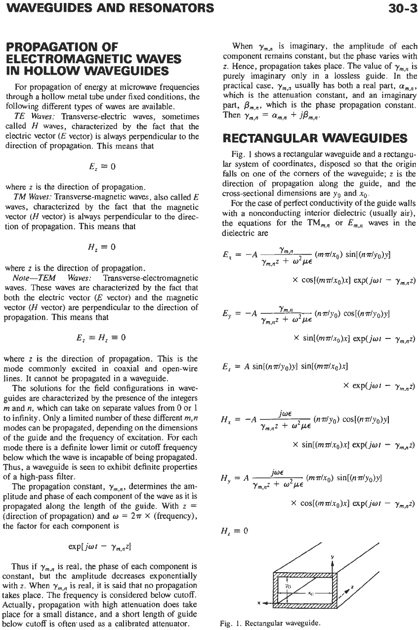
Fig.
1
shows a rectangular waveguide and a rectangu-
lar system of coordinates, disposed
so
that the origin
falls on one of the comers of the waveguide;
z
is
the
direction of propagation along the guide, and the
cross-sectional dimensions are yo and xo.
For the case of perfect conductivity of the guide walls
with a nonconducting interior dielectric (usually air),
the equations for the
TM,,,
or
E,,,
waves in the
dielectric
are
X
cos[(m?r/xo)x] exp(jat
-
y,,,z)
x
sin[(m7r/xo)x] exp(jot
-
ym,,z)
E,
=
A
sin[(n7r/yo)y] sin[(m7r/xo)x]
x
sin[(m7r/xo)x] exp(jot
-
y,,+z)
X
cos[(m7r/xo)x] exp(jwt
-
y,,,z)
H,
=
0
Fig.
1.
Rectangular
waveguide.
30-4
REFERENCE
DATA
FOR
ENGINEERS
where
E
is the dielectric constant and
/L
the permeability
of the dielectric material in meter-kilogram-second
(rationalized) units.
Constant
A
is determined solely by the exciting
voltage. It has both amplitude and phase. Integers
m
and
n
may individually take values from
1
to infinity.
No
TM waves of the
0,O
type
or
1
,O
type are possible in
a rectangular guide,
so
neither
m
nor
n
may be
0.
Equations for the TE,,n waves
or
H,,n
waves in a
dielectric are
X
cos[(m.rr/xo)x] exp(jwt
-
Y,,~z)
x
sin[(m.rr/xo)x] exp(jot
-
ym,,z)
E,
=
0
x
sin[(m.rr/xo)x] exp(jot
-
y,,,z)
x
cos[(m.rr/xo)x] exp(jot
-
ym,nz)
H,
=
B
cos[(n.rr/yo)y] cos[(m?r/x~)x]
x
exp(jot
-
Ym,nz)
Constant
B
depends only on the original exciting
voltage and has both magnitude and phase;
m
and
n
individually may assume any integer value from
0
to
infinity. The
0,O
type
of
wave where both
m
and
n
are
0
is not possible; all other combinations are.
As
stated previously, propagation takes place only
when propagation constant
ym,n
is imaginary.
Y,,~
=
[(m?r/x0)’
+
(n.rr/y0)’
-
o’p~]~”
This means, for any
m,n
mode, propagation takes
place when
W*/LE
>
(m.rr/xo)2
+
(n.rr/yo)’
or, in terms
of
frequencyfand velocity of light
c,
when
where
pI
and
E]
are the relative permeability and
relative dielectric constant, respectively, of the dielec-
tric material with respect to free space.
The wavelength in the air-filled waveguide is always
greater than the wavelength in free space. The wave-
length in the dielectric-filled waveguide may be less
than the wavelength in free space. If
A
is the wavelength
in free space and the medium filling the waveguide has a
relative dielectric constant
E,
A
hg(m’n)
=
[E
-
(mA/2xo)’
-
(nA/2yo)2]1’2
where
(llh,)’
=
(m/2xO)*
+
(n/2y0)’.
The phase velocity within the guide
is
also always
greater than in an unbounded medium. The phase
velocity,
v,
and group velocity,
u,
are related by
u
=
c’/v
where the phase velocity is given by
v
=
cA,/A,
and the
group velocity is the velocity
of
propagation of the
energy.
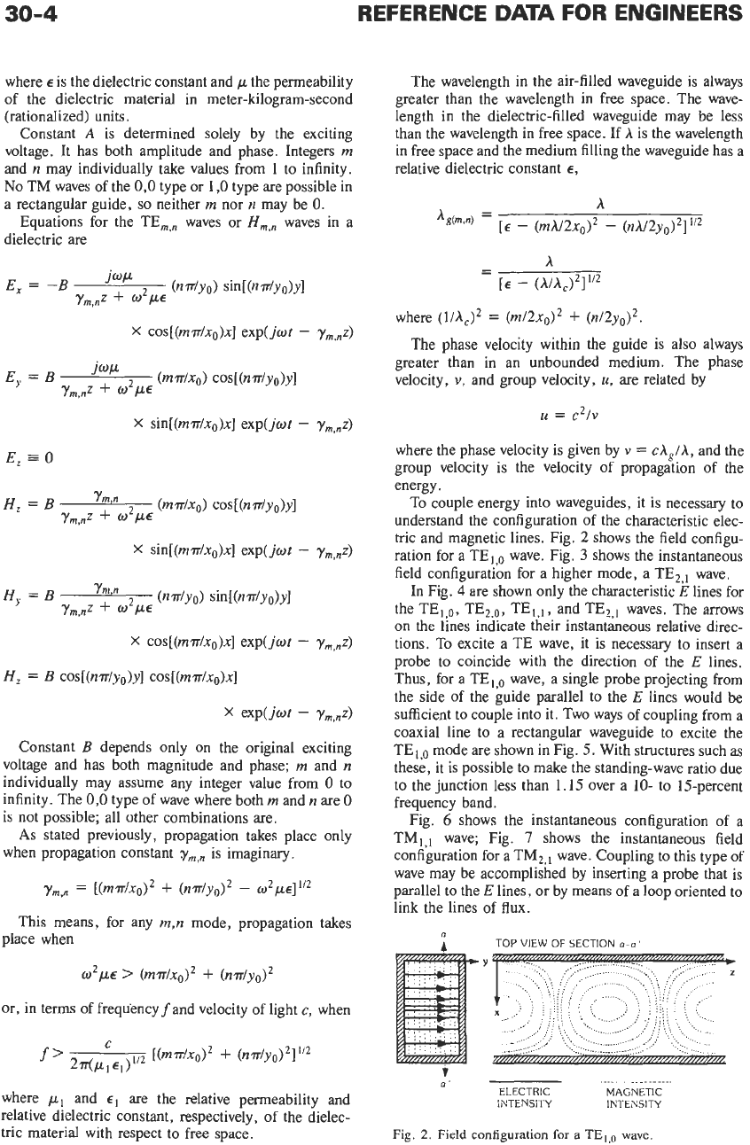
To couple energy into waveguides, it is necessary to
understand the configuration of the characteristic elec-
tric and magnetic lines. Fig.
2
shows the field configu-
ration for a TE,,, wave. Fig.
3
shows the instantaneous
field configuration for a higher mode, a TE,,, wave.
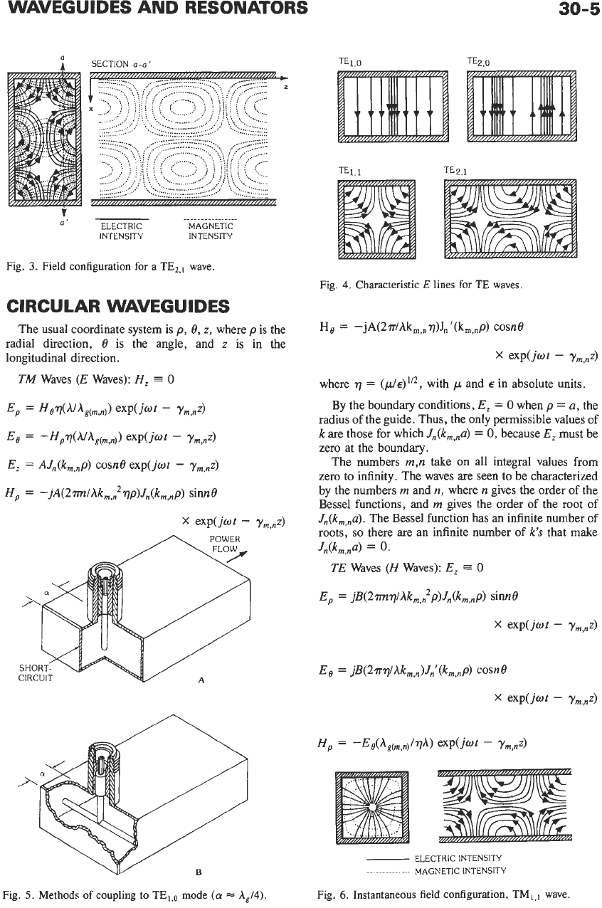
In Fig.
4
are
shown only the characteristic E lines for
the TEl,o, TE2,0, TEI,,, and TE,,, waves. The arrows
on
the lines indicate their instantaneous relative direc-
tions. To excite a TE wave, it is necessary to insert a
probe to coincide with the direction of the E lines.
Thus, for a TE,,, wave, a single probe projecting from
the side of the guide parallel to the
E
lines would be
sufficient to couple into it. TWO ways of coupling from a
coaxial line to a rectangular waveguide to excite the
TE,,, mode are shown in Fig.
5.
With structures such as
these, it is possible to make the standing-wave ratio due
to the junction less than
1.15
over a
10-
to 15-percent
frequency band.
Fig.
6
shows the instantaneous configuration of a
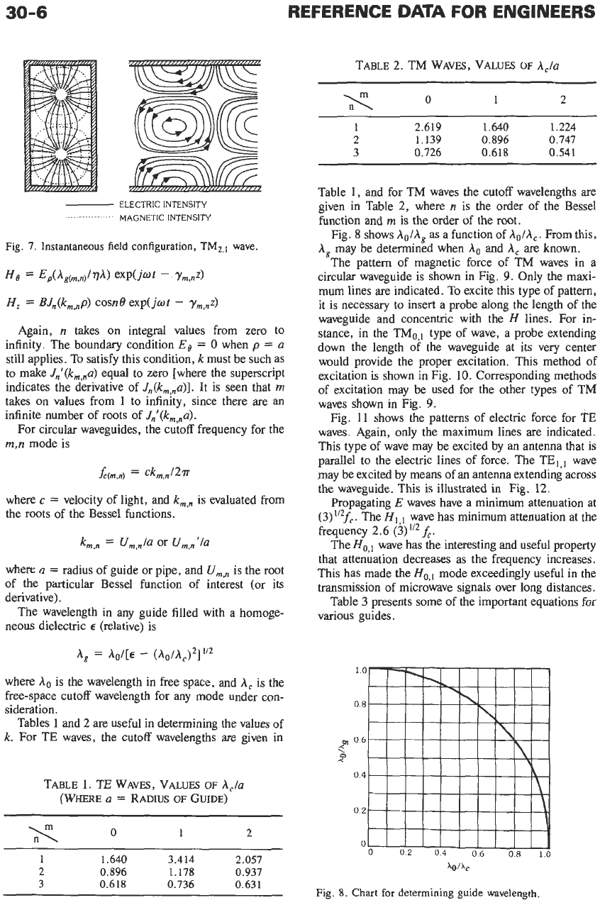
TM,,, wave; Fig.
7
shows the instantaneous field
configuration for a TM2,1 wave. Coupling to this type of
wave may be accomplished by inserting a probe that is
parallel to the
E
lines, or by means
of
a loop oriented
to
link the lines of
flux.
0
I
TOP VIEW
OF
SECTION
0-0’
.
.
..
.
.
.
.
..
.
.
ELECTRIC MAGNETIC
INTENSITY
IN
T E
N
5
IT Y
a’
Fig.
2.
Field configuration for
a
TE,,,
wave.
WAVEGUIDES AND RESONATORS
30-5
a
I
SECTION
a-o'
................
ELECTRIC MAGNETIC
INTENSITY INTENSITY
(I'
Fig.
3.
Field configuration
for
a
TE2,,
wave.
CIRCULAR WAVEGUIDES
The usual coordinate system
is
p,
8,
z,
where
p
is the
radial direction,
8
is the angle, and
z
is in the
longitudinal direction.
TM
Waves
(E
Waves):
H,
=
0
Ep
=
HaT(A/Ag(rn,n))
exp(jwt
-
Ym,nz)
Ea
=
-HpT(A/Ag(rn,n))
exp(jwt
-
Ym,A
E,
=
AJn(k,,np)
cosne exp(jwt
-
y,,,z)
Hp
=
-jA(2rm/Ak,,2qp)Jn(k,,np)
sinn8
Fig.
5.
B
Methods
of
coupling
to
TE,,,
mode
(a
=
AJ4).
Fig.
4.
Characteristic
E
lines
for
TE
waves.
Ha
=
-jA(2?r/Akm,"q)J, '(k,,"p)
cosne
X
expW
-
Y,,,z)
where
q
=
(~/L./E)"~,
with
p
and
E
in absolute units.
By the boundary conditions,
E,
=
0
when
p
=
a,
the
radius of the guide. Thus, the only permissible values of
k
are
those for which
J,(k,,,u)
=
0,
because
E,
must be
zero at the boundary.
The numbers
m,n
take on all integral values from
zero to infinity. The waves are seen to be characterized
by the numbers
m
and
n,
where
n
gives the order of the
Bessel functions,
and
m
gives the order of the root of
Jn(k,,na).
The Bessel function has an infinite number of
roots,
so
there are an infinite number
of
k's
that make
Jn(km,na)
=
0.
TE
Waves
(H
Waves):
E,
=
0
E,
=
jB(2mq/Akm,2p)Jn(k,,p)
sinn8
~
ELECTRIC INTENSITY
.............
MAGNETIC INTENSITY
Fig.
6.
Instantaneous
field
configuration, TM,,,
wave.
30-6
REFERENCE
DATA
FOR ENGINEERS
-
ELECTRIC INTENSITY
.
. .
. .
.
. .
.
.
.
..
.
.
.
.
MAGNETIC INTENSITY
Fig.
7.
Instantaneous field configuration,
TM2.1
wave.
He
=
Ep(Ag~,,,,)/~A)
exp(jof
-.
Ym,nZ)
H,
=
BJ,(k,,,p)
cosne exp(jof
-
y,,,z)
Again,
n
takes on integral values from zero to
infinity. The boundary condition
EB
=
0
when
p
=
a
still applies. To satisfy this condition,
k
must be such as
to make
J,'(k,,,u)
equal to zero [where the superscript
indicates the derivative of
J,(k,,,u)].
It is seen that
m
takes
on
values from
1
to infinity, since there
are
an
infinite number of roots of
J,'(k,,a).
For circular waveguides, the cutoff frequency for the
m,n
mode is
A(,,,)
=
ckm,n/2r
where
c
=
velocity of light, and
k,,,
is evaluated from
the roots of the Bessel functions.
k,,,
=
U,,/a
or
U,,'lu
where
a
=
radius of guide or pipe, and
Urn,,,
is the root
of the particular Bessel function of interest (or its
derivative).
The wavelength in any guide filled with a homoge-
neous dielectric
E
(relative) is
A,
=
&/[E
-
(AolAc)2]'/2
where
A,
is the wavelength in free space, and
A,
is the
free-space cutoff wavelength for any mode under con-
sideration.
Tables
1
and
2
are
useful in determining the values of
k.
For TE waves, the cutoff wavelengths are given in
TABLE
1.
TE WAVES, VALUES
OF
Acta
(WHERE
U
=
RADIUS
OF
GUIDE)
x
0
1
2
~~
1
1.640
3.414 2.057
2 0.896
1.178 0.937
3 0.618
0.736
0.631
TABLE
2.
TM WAVES, VALUES
OF
Acta
0
1
2
1
2.619 1.640 1.224
2 1.139 0.896 0.747
3
0.726
0.618 0.541
Table
1,
and for TM waves the cutoff wavelengths are
given in Table
2,
where
n
is the order of the Bessel
function and
m
is the order
of
the root.
Fig.
8
shows
Aol,Ag
as a function of
A,lh,.
From this,
A,
may be determined when
A.
and
A,
are known.
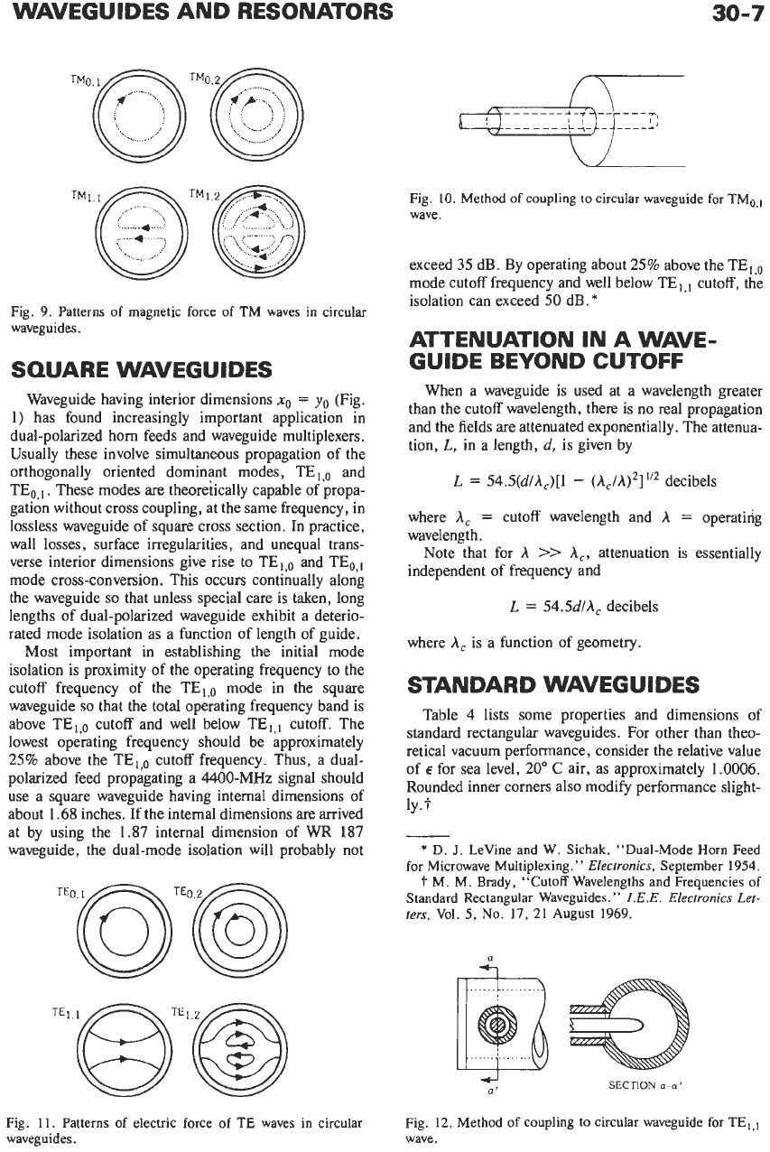
The pattern of magnetic force of TM waves in a
circular waveguide is shown in Fig.
9.
Only the maxi-
mum lines
are
indicated. To excite this type of pattern,
it is necessary to insert a probe along
the
length of the
waveguide and concentric with the
H
lines. For in-
stance, in the TM0,' type of wave, a probe extending
down the length of the waveguide at its very center
would provide the proper excitation. This method of
excitation is shown in Fig.
10.
Corresponding methods
of excitation may be used for the other types of TM
waves shown in Fig.
9.
Fig.
11
shows the patterns of electric force for
?E
waves. Again, only the maximum lines
are
indicated.
This type of wave may be excited by an antenna that is
parallel to the electric lines of force. The TE,,, wave
may be excited by means of an antenna extending across
the waveguide. This is illustrated in Fig.
12.
Propagating
E
waves have a minimum attenuation at
(3)
'"f,.
The
H
wave has minimum attenuation at the
frequency
2.6 (3)
f,
.
The
Ho,,
wave has the interesting and useful property
that attenuation decreases as the frequency increases.
This has made the
H0,'
mode exceedingly useful in the
transmission
of
microwave signals over long distances.
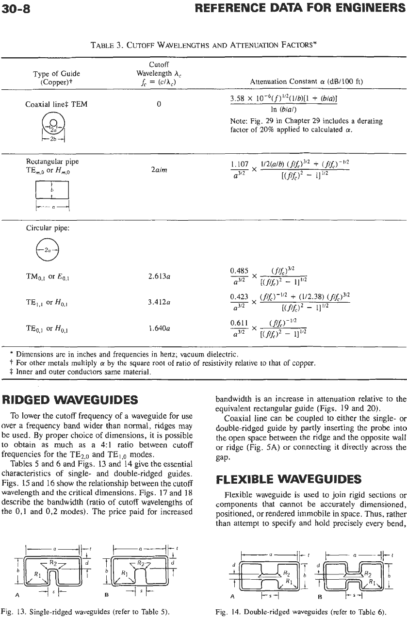
Table
3
presents some of the important equations for
various guides.
AO&
Fig.
8.
Chart
for determining guide wavelength.
WAVEGUIDES AND RESONATORS
30-7
TMl,(-J
........
................
*
......
.......
*
.......
?
\.,
.....
..........
~
Fig.
9.
Patterns
of
magnetic force of TM
waves
in circular
waveguides.
SQUARE WAVEGUIDES
Waveguide having interior dimensions
no
=
yo
(Fig.
1) has found increasingly important application in
dual-polarized horn feeds and waveguide multiplexers.
Usually these involve simultaneous propagation of the
orthogonally oriented dominant modes, TE,
,o
and
TE?,,. These modes are theoretically capable of propa-
gation without cross coupling, at the same frequency, in
lossless waveguide of square cross section.
In
practice,
wall losses, surface irregularities, and unequal trans-
verse interior dimensions give rise to TE!,, and TE,,,
mode cross-conversion. This occurs continually along
the waveguide
so
that unless special care is taken, long
lengths of dual-polarized waveguide exhibit a deterio-
rated mode isolation as a function of length of guide.
Most important in establishing the initial mode
isolation is proximity of the operating frequency to the
cutoff frequency of the TE,,, mode in the square
waveguide
so
that the total operating frequency band is
above TEl,o cutoff and well below TE,,, cutoff. The
lowest operating frequency should be approximately
25%
above the TElp cutoff frequency. Thus, a dual-
polarized feed propagating a 4400-MHz signal should
use a square waveguide having internal dimensions of
about 1.68 inches. If the internal dimensions are arrived
at by using the 1.87 internal dimension of WR 187
waveguide, the dual-mode isolation will probably not
TEo@TEo@,
Fig.
11.
Patterns of electric force
of
TE
waves
in
circular
waveguides.
Fig. 10.
Method
of
coupling
to circular
waveguide
for TMo,,
wave.
exceed
35
dB. By operating about
25%
above the
TEIp
mode cutoff frequency and well below TE,,, cutoff, the
isolation can exceed
50
dB.
*
ATTENUATION
IN
A WAVE-
GUIDE BEYOND CUTOFF
When a waveguide is used at a wavelength greater
than the cutoff wavelength, there is
no
real propagation
and the fields are attenuated exponentially. The attenua-
tion,
L,
in a length,
d,
is given by
L
=
54.5(d/Ac)[1
-
(Ac/A)2]1’2
decibels
where
A,
=
cutoff wavelength and
A
=
operating
wavelength.
Note that for
A
>>
A,,
attenuation is essentially
independent of frequency and
L
=
54.5d/AC
decibels
where
A,
is a function of geometry.
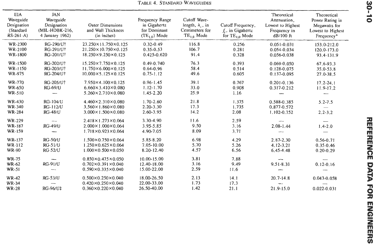
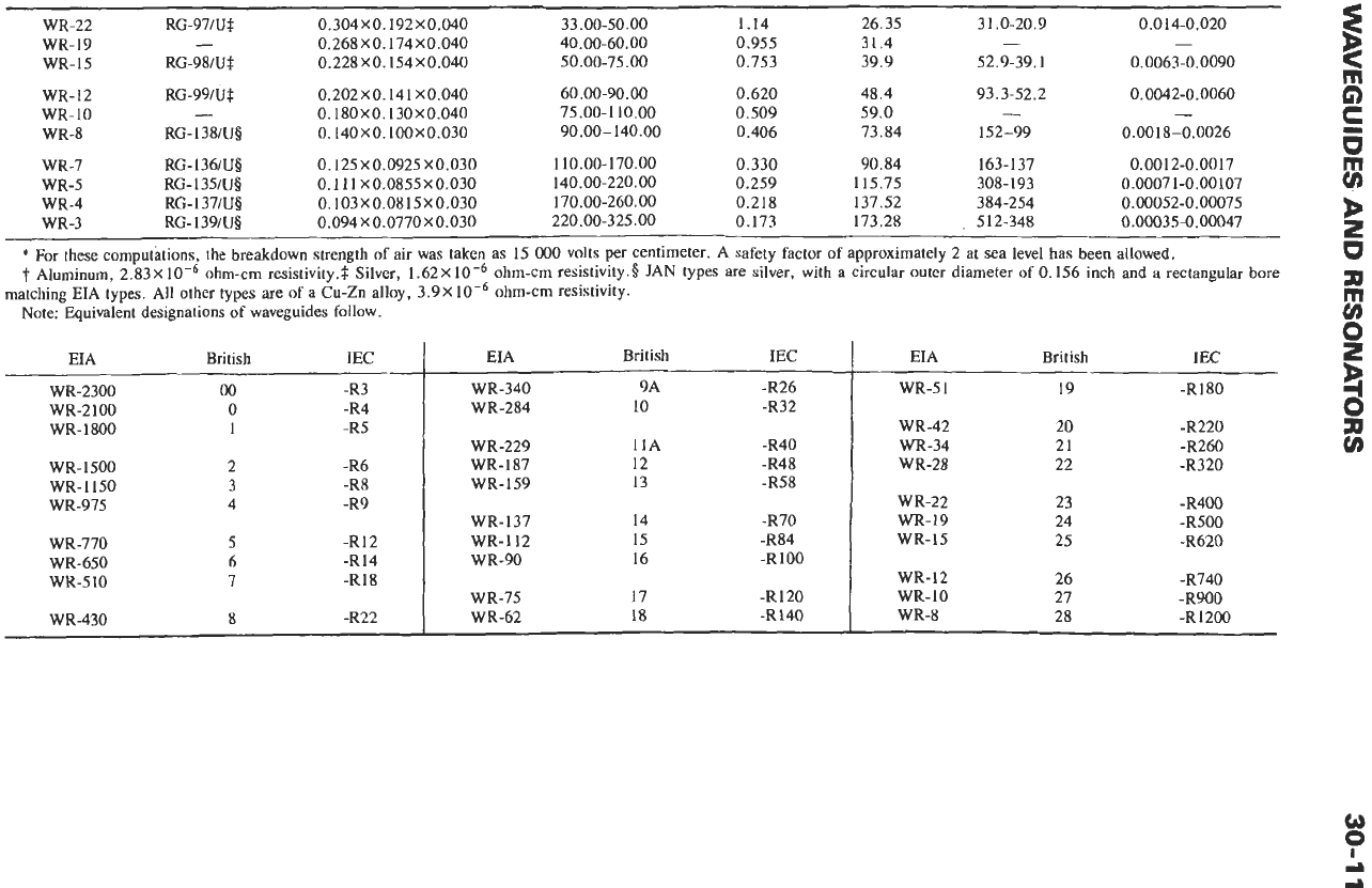
STANDARD WAVEGUIDES
Table
4
lists some properties and dimensions of
standard rectangular waveguides. For other than theo-
retical vacuum performance, consider the relative value
of
E
for sea level,
20”
C
air, as approximately 1.0006.
Rounded inner corners also modify performance slight-
ly.?
-
*
D.
J.
LeVine
and
W.
Sichak,
“Dual-Mode Horn Feed
for Microwave Multiplexing.
”
Electronics,
September 1954.
‘l
M.
M. Brady,
“Cutoff
Wavelengths and Frequencies of
Standard Rectangular Waveguides.”
Z.E.E.
EZectronics
Let-
ters,
Vol.
5,
No.
17,
21 August 1969.
*
...............
a’
SECTION
0-0’
Fig.
12.
Method
of
coupling
to
circular waveguide
for
TE,,,
wave.
30-8
REFERENCE
DATA
FOR
ENGINEERS
TABLE
3.
CUTOFF
WAVELENGTHS
AND
ATTENUATION
FACTORS*
cutoff
Type
of
Guide Wavelength
A,
(CopPerS
f,
=
(c/U
Attenuation Constant
a
(dB1100
ft)
Coaxial
line$ TEM
0
3.58
x
10-6(f)”z(l/b)[l
+
(b/a)l
In
(b/a/)
Note:
Fig.
29
in Chapter
29
includes
a
derating
factor
of
20% applied to calculated
a.
2a/m
2.613~
3.412~
1
,640~
*
Dimensions are
in
inches
and frequencies
in
hertz; vacuum dielectric.
‘t
For other metals multiply
a
by
the square root
of
ratio
of
resistivity relative to that
of
copper.
$
Inner and outer conductors same material.
RIDGED WAVEGUIDES
To lower the cutoff frequency of a waveguide for use
over
a
frequency band wider than normal, ridges may
be used. By proper choice
of
dimensions, it is possible
to obtain as much as a 4:l ratio between cutoff
frequencies for the TE2,0 and TEl,o modes.
Tables 5 and
6
and Figs.
13
and
14
give the essential
characteristics of single- and double-ridged guides.
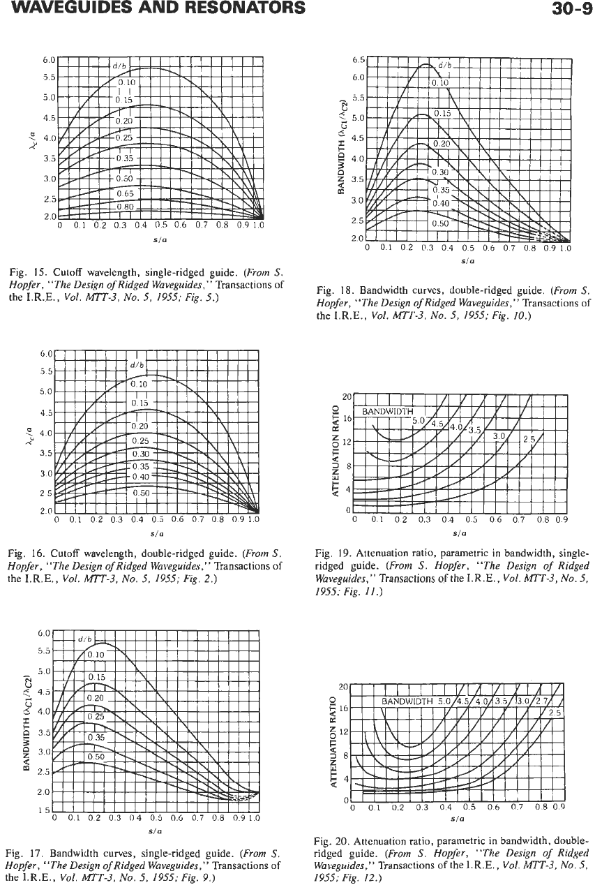
Figs. 15 and
16
show the relationship between the cutoff
wavelength and the critical dimensions. Figs.
17
and
18
describe the bandwidth (ratio
of
cutoff wavelengths
of
the
0,l
and
0,2
modes). The price paid for increased
A
4.k
B
-1st-
Fig.
13.
Single-ridged waveguides (refer
to
Table
5).
bandwidth is an increase in attenuation relative to the
equivalent rectangular guide (Figs.
19
and
20).
Coaxial line can be coupled to either the single- or
double-ridged guide by partly inserting the probe into
the open space between the ridge and the opposite wall
or ridge (Fig.
5A)
or
connecting it directly across the
gap.
FLEXIBLE WAVEGUIDES
Flexible waveguide is used to join rigid sections or
components that cannot be accurately dimensioned,
positioned, or rendered immobile in space. Thus, rather
than attempt
to
specify and hold precisely every bend,
A
t-si
6
ksj
Fig. 14. Double-ridged waveguides (refer
to
Table
6).
WAVEGUIDES AND RESONATORS
30-9
60
55
50
45
5
40
Y
35
30
25
20
0
01
02
03
04
05
06
07
08
0910
sfa
Fig.
15.
Cutoff wavelength, single-ridged guide.
(From
S.
Hopfer, “The Design
of
Ridged Waveguides,”
Transactions
of
the I.R.E.,
Vol.
MTT-3,
No.
5, 1955; Fig.
5.)
60
55
50
45
?
4.0
3.5
3.0
25
2.0
r<
0
0.1
0.2
0.3
04
0.5
0.6
0.7
0.8
0.910
sla
Fig.
16.
Cutoff wavelength, double-ridged guide.
(From
S.
Hopfer, “The Design of Ridged Waveguides,’’
Transactions
of
the I.R.E.,
Vol.
MTT-3,
No.
5, 1955; Fig.
2.)
60
55
50
-
d
<
45
G
z
35
5
6
40
I
30
25
20
15
a
0
01
02
03
04
05
06
07
08
0910
65
60
-
55
El
G
50
45
F
$
40
z
35
30
25
20
a
m
0
01
02
03 04
05
06
07
08
0910
sla
Fig.
18.
Bandwidth curves, double-ridged guide.
(From
S.
Hopfer, “The Design
of
Ridged Waveguides,”
Transactions
of
the I.R.E.,
Vol.
MTT-3,
No.
5,
1955; Fig.
IO.)
20
2
16
E
12
38
0
2
6
54
0
0
01 02
03 04
05
06
07
08
09
sla
Fig.
19.
Attenuation ratio, parametric in bandwidth, single-
ridged guide.
(From
s.
Hopfer, “The Design
of
Ridged
Waveguides,”
Transactions
of
the I.R.E.,
VoL.
MTT-3,
No.
5,
1955; Fig.
11.)
20
0
2
16
s
l2
38
2
5
54
0
0
01
02
03
04
05
06
07
0809
sla
sla
Fig.
17.
Bandwidth curves, single-ridged guide.
(From
S.
Hopfer, “The Design
of
Ridged Waveguides,’’
Transactions
of
the I.R.E.,
Vol.
MTT-3,
No.
5,
1955;
Fig.
9.)
Fig.
20.
Attenuation ratio, parametric in bandwidth, double-
ridged guide.
(From
s.
Hopfer, “The Design
of
Ridged
Waveguides,’’
Transactions
of
the I.R.E.,
Vol.
MTT-3,
No.
5,
1955; Fig.
12.)
Ij
TABLE
4.
STANDARD WAVEGUIDES
-
I
d
Theoretical
EIA
JAN
Theoretical
Waveguide Waveguide Frequency
Range
Cutoff
Wave-
Attenuation, Power Rating
in
0
Designation
Designation Outer Dimensions
in
Gigahertz length,
A,,
in
Cutoff Frequency,
Lowest
to
Highest
Megawatts
for
(Standard
(MIL-HDBK-216,
and
WaIl
Thickness
for
Dominant Centimeters for
A,,
in
Gigahertz Frequency in
Lowest
to
Highest
RS-261-A)
4
January
1962)
(in inches)
(TEI,o)
Mode
TE,,o
Mode
for
TE
I
,o
Mode
dB1100
ft
Frequency*
WR-2300
WR-2100
WR- 1800
WR-1500
WR-
1
150
WR-975
WR-770
WR-650
WR-5 10
WR430
WR-340
WR-284
WR-229
WR-187
WR-159
WR-137
WR-112
WR-90
WR-75
WR-62
WR-51
WR-42
WR-34
WR-28
RG-290/Ut
RG-2911ut
RG-2Ol/Ut
RG-202lUt
RG-203/UT
RG-204/Ut
RG-205/Ut
RG-69N
-
RG-IWU
RG-112lU
RG-48/U
-
RG-49N
-
RG-SORI
RG-51IU
RG-52IU
-
RG-91lU
-
RG-53N
RG-96lU
f
-
23.250X11.750X0.125
21.250X 10.750X0.125
18.250X 9.250XO. 125
15.250X7.750X0.125
11.75OX6.OOOXO.125
1O.OOOX 5.125
XO.
125
7.95ox4.1ooxo.125
6.660X3.410X0.080
5.260X2.7 10 X0.080
4.460X2.310X0.080
3.560X 1.860X0.080
3.000X 1.500X0.080
2.418X 1.273XO.064
2.OOox
1
.oooxo.o64
1.718X0.923X0.064
1.500X0.750X0.064
1.250X0.625X0.064
1.000X0.500X0.050
0.850X0.475X0.050
0.702X0.39
1
X0.040
0.590X0.335X0.040
0.500X0.250X0.040
0.420X0.250X0.040
0.360X0.220X0.040
0.32-0.49
0.35-0.53
0.425-0.620
0.49-0.740
0.64-0.96
0.75-1.12
0.96- 1.45
1.12-1.70
1.45-2.20
1.70-2.60
2.20-3.30
2.60-3.95
3.30-4.90
3.95-5.85
4.90-7.05
5.85-8.20
7.05-
10.00
8.20-12.40
10.00- 15
.OO
12.40-18.00
15.00-22.00
18.00-26.50
22.00-33.00
26.50-40.00
116.8
106.7
91.4
76.3
58.4
49.6
39.1
33.0
25.9
21.8
17.3
14.2
11.6
9.50
8.09
6.98
5.70
4.57
3.81
3.16
2.59
2.13
1.73
1.42
0.256
0.281
0.328
0.393
0.514
0.605
0.767
0.908
1.16
1.375
1.735
2.08
2.59
3.16
3.71
4.29
5.26
6.56
7.88
9.49
11.6
14.1
17.3
21.1
0.051-0.031
0.054-0.034
0.056-0.038
0.069-0.050
0.1374.095
0.128-0.075
0.201-0.136
0.317-0.212
-
0.588-0.385
0.877-0.572
1.102-0.752
-
2.08-1.44
-
2.87-2.30
4.12-3.21
6.45-4.48
-
9.5 1-8.3 1
-
20.7-14.8
-
21.9-15.0
1 53.0-2 12.0
120.0-173.0
93.4-131.9
67.6-93.3
35.0-53.8
27 .O-38.5
17.2-24.1
11.9-17.2
-
5.2-7.5
-
2.2-3.2
-
1.4-2.0
-
0.56-0.71
0.35-0.46
0.20-0.29
-
0.12-0.16
-
0.043-0.058
-
0.022-0.03
1
WR-22 RG-97IUl
0.304X0.192X0.040 33.00-50.00
1.14 26.35
31.0-20.9 0.014-0.020
WR-19
-
0.268
X
0.174 X0.040 40.00-60.00
0.955 31.4
-
-
WR-15 RG-98/U#
0.228
X
0.154
X
0.040 50.00-75.00
0.753 39.9
52.9-39.1 0.0063-0.0090
WR-12
RG-99lUl
0.202X0.141X0.040 60.00-90.00
0.620 48.4
93.3-52.2 0.0042-0.0060
WR-IO
-
0.180X0.130X0.040 75.00-1 10.00
0.509 59.0
-
-
WR-8 RG-l38/Ug
0.140X0.100X0.030 90
.OO-
140.00
0.406 73.84
152-99 0.0018-0.0026
WR-7 RG-l36/Ug
0.125 X0.0925 X0.030 110.00-170.00
0.330 90.84 163-137
0.0012-0.0017
0.259 115.75 308-193 0.00071-0.00107
WR-5
RG-l35/U$
0.
I1
I
X0.0855X0.030 140.00-220.00
WR-4 RG-l37/Ug
0.103
X
0.08
15
X
0.030 170.00-260.00 0.218 137.52 384-254 0.00052-0.00075
WR-3 RG-1391UB 0.094X0.0770X0.030 220 .OO-325
.OO
0.173 173.28
.
512-348 0.00035-0.00047
*
For
these computations, the breakdown strength
of
air
was
taken as
15
000
volts
per
centimeter. A safety factor
of
approximately
2
at sea level has been allowed.
t
Aluminum,
2.83X10⁻⁶
ohm-cm resistivity.$ Silver,
1.62X10⁻⁶
ohm-cm resistivity.8 JAN types
are
silver, with a circular outer diameter
of
0.156
inch and a rectangular bore
Note: Equivalent designations of waveguides follow.
matching EIA types. All other
types
are
of
a
Cu-Zn
alloy,
3.9X
ohm-crn resistivity.
EIA British IEC
WR-2300
00
-R3
WR-1800
1
-R5
WR-2
100
0
-R4
WR-1500 2 -R6
WR-1150 3 -R8
WR-975 4 -R9
WR-770 5 -R12
WR-650 6 -R14
WR-510 7 -R18
WR-430
8
-R22
EL4
British
IEC
WR-340
WR-284
WR-229
WR-
187
WR-159
WR-137
WR-112
WR-90
WR-75
WR-62
9A
10
11A
12
13
14
15
16
17
18
-R26
-R32
-R40
-R48
-R58
-R70
-R84
-R
100
-R120
-R140
EIA British
WR-51
WR-42
WR-34
WR-28
WR-22
WR-19
WR-15
WR-12
WR-IO
WR-8
19
20
21
22
23
24
25
26
27
28
IEC
-R
180
-R220
-a60
-R320
-R400
-R500
-R620
8740
-R900
-R
1200