Middleton W.M. (ed.) Reference Data for Engineers: Radio, Electronics, Computer and Communications
Подождите немного. Документ загружается.

31-10
REFERENCE
DATA
FOR ENGINEERS
Conversely
s
=
(1
-
Y)(1
+
Y)-l
=
(Z
-
1)(Z
+
l)-l
0%.
29)
These equations may be used as definitions for the
scattering matrix of lumped-constant networks with
n
terminal pairs. This is equivalent to considering the
network
as
a junction between
n
transmission
lines
of
unit characteristic impedance.
If the network or the junction is reciprocal,
Y
and
Z
are purely imaginary.
For a two-port junction,
Eq.
28
becomes
Y
=
(1
-
S)(1
+
s)-l
=
[det
(1
+
S)]-'
I
1
-
det
S
+
(s22
-
sll)
-2s12
1
-
det
S
-
(s2*
-
sll)
and
z
=
(1
+
S)(1
-
q-1
=
[det
(1
-
S)]-'
1
1
-
det
S
-
(s22
-
sIl)
2s
12
1
-
det
S
+
(s22
-
sI1)
det
(1
+
S)
=
1
+
tr
S
+
det
S
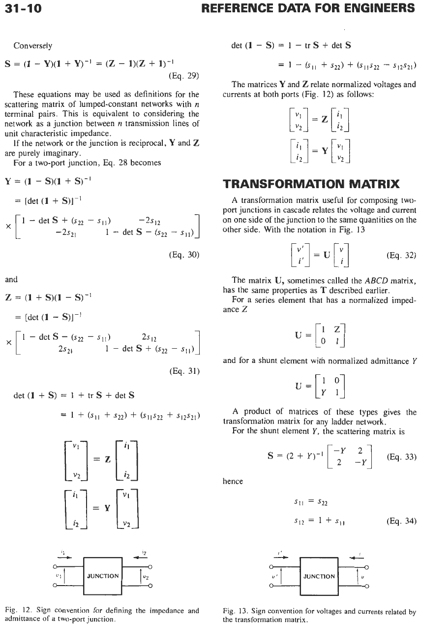
[::I
=
[::I
[I
=
[:I
Fig.
12.
Sign convention for defining the impedance and
admittance of
a
two-port junction.
det
(1
-
S)
=
1
-
tr
S
+
det
S
=
1
-
(SI1
+
s22)
+
ells22
-
s12s21)
The matrices
Y
and
Z
relate normalized voltages and
currents at both ports (Fig.
12)
as follows:
[:I
=
[:;I
[::I
=
[:;I
TRANSFORMATION MATRIX
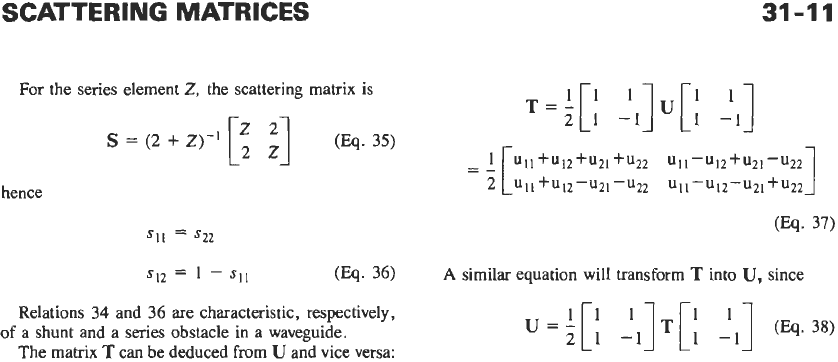
A
transformation matrix useful for composing two-
port junctions in cascade relates the voltage and current
on one side of the junction to the same quantities on the
other side. With the notation in Fig.
13
The matrix
U,
sometimes called the
ABCD
matrix,
For a series element that has a normalized imped-
has the same properties as
T
described earlier.
ance
Z
u=
[;
;]
and for a shunt element with normalized admittance
Y
u=[:
(3
A
product of matrices of these types gives the
For the shunt element
Y,
the scattering matrix is
transformation matrix for any ladder network.
S
=
(2
+
Y)-l
1
-Y
-y]
2
(Eq.
33)
hence
SI1
=
s22
SI*
=
1
+
SI1
Fig.
13.
Sign convention for voltages and currents related
by
the transformation matrix.
SCATTERING MATRICES
31-11
T='['
-lI]U[l
'1
For the series element
Z,
the scattering matrix
is
21
1 -1
z2
S
=
(2
+
Z)-'
[2
(Eq. 35)
hence
1
s12
=
1
-
SI]
(m.
36)
A
similar equation will transform
T
into
U,
since
Relations 34 and 36 are characteristic, respectively,
The matrix
T
can be deduced from
U
and vice versa:
of a shunt and a series obstacle in a waveguide.
.=A['
21]T[1
1 -1
'1
(Eq.38)
21
32
Antennas
Robert
C.
Hansen
General
32-3
Introduction
Definitions
Small Antennas
Superconducting Antennas
Near-Field Power Density
Antenna Noise Temperature
Elliptical and Circular Polarization
Low-Gain Antennas
32-13
Half-Wave Dipole
Radial-Wire Ground Systems
Printed-Circuit Antennas
Slot Antennas
Loops
Medium-Gain Antennas
32-22
Horns
Helices
Yagi-Uda Antennas
Frequency -Independent Antennas
Log-Periodic Antennas
Fractal Antennas
Arrays
32-32
General Characteristics
Grating and Quantization Lobes
Linear Array Feeds
32-
1
32-2
REFERENCE
DATA
FOR ENGINEERS
Mutual Impedance
Thinned Arrays
Tolerances
Multiple-Beam Arrays
Electronic Scanning
Adaptive Arrays
Aperture Distributions
32-47
Design
of
Distributions
Taylor One-Parameter Line Source Distribution
Taylor
fi
Line Source Distribution
Bayliss
fi
One-Parameter Difference Line Source
Low Sidelobe Distributions
Measurement
of
Low-Sidelobe Patterns
Hansen One-Parameter Circular Source Distribution
Taylor
fi
Circular Source Distribution
Reflectors
32-54
Parabolic Reflectors
Scanning and Multiple-Beam Reflectors
32-3
GENERAL
Introduction
The field of antennas is sufficiently broad to be
beyond the scope of this chapter, even for succinct
design information. Thus the intent is to be eclectic
rather than inclusive. Fortunately, several excellent
books on antennas are available. For more detailed
design data, the reader should consult the two-volume
Handbook
of
Antenna Design
edited by Rudge et al.*
Thorough texts on antenna theory, including extensive
coverage of the powerful geometric theory of diffrac-
tion (GTD) and moment method analytical approaches,
as well as exemplary computer programs, are by Bala-
nist
and by Stutzman and Thiele.$ A third excellent
text, which has extensive coverage on fixed beam may
design, is by Elliott.§ Finally, the most extensive treat-
ment of phased arrays (electronic scanning) is
Phased
Array Antennas
by Hansen;” another useful book is
still the three-volume
Microwave Scanning Antennas
by Hansen.#
Six parts comprise this chapter. Basic antenna
behavior, including definitions, fields, near-field power
density, antenna noise temperature, and polarization
coupling are in the general part. The next two parts
cover, respectively, low- and medium-gain antennas,
where dipoles, slots, loops, and microstrip patches are
low gain, and horns, Yagi-Udas, helices, spirals, and
log-periodics are medium-gain. Arrays
of
all
types are
covered next. Aperture distributions, because of their
common importance, occupy an entire part. Finally,
reflector-type antennas are the subject of the last part.
Some old favorites have been left out, and this reflects
somewhat the changing antenna usage.
Because of the power and ready availability of cal-
culators and computers, tables of calculated functions
have largely been omitted. Instead, key performance
indices have been quantified, with design formulas
given
so
that the designer can implement them
directly.
Definitions
Directivity and gain are measures of how well
energy is concentrated in a given direction. Directivity
*
Rudge.
A.
W., et
al.
(Eds.).
Handbook
of
Antenna De-
sign.
London:
Peter Peregrinus
Ltd.,
1983.
t
Balanis, C. A,,
Antenna Theory: Analysis and Design.
New
York
John
Wiley
&
Sons,
Inc., 1997.
$
Stutzman, W.
L.,
and Thiele, G.
A.
Antenna Theory and
Design.
New
York
John
Wiley
&
Sons, Inc., 1998.
5
Elliott, R.
S.
Antenna Theory and Design.
Englewood
Cliffs. NJ: F’rentice-Hall, Inc., 1981.
‘‘
Hansen, R. C.
Phased Array Antennas.
New
York
John
Wiley
&
Sons,
Inc., 1998.
#
Hansen,
R.
C.
Microwave Scanning Antennas.
New
York:
Academic Press, Inc.; Vol. 1,1964; Vols.
2
and 3,1966;
Los
Altos, CA: Peninsula Publ., 1985.
is the ratio of power density (PD) in that direction to
the power density that would be produced if the power
were radiated isotropically. The reference can be lin-
early or circularly polarized, and directivity is often
given in dBi, decibels above isotropic. Some early lit-
erature refers to gain above a dipole; this usage is dep-
recated, as it is confusing and unnecessary. Directivity,
then, is given by
Gain includes antenna losses; thus gain is the field
intensity produced in the given direction by a fixed
input power to the antenna. Gain is related to directiv-
ity by efficiency
q,
and is
G=Dq
G
=
4rPDIPi,
Through reciprocity, directivity is independent
of
transmission or reception, as is gain. Gain, as widely
used in the industry, includes the impedance mismatch
factor. However, the academic gain does not.
Effective area is defined by:
A,
=
h2G/4r
where
h
is the free-space wavelength. (All through this
chapter, commonly used symbols are employed.) For
an antenna matched to a load, the load power is
Plead
=
PD
.
A,,
where
PD
is the power density at the antenna
in watts per square meter.
Path loss is
part
of the range equation, where
received power is related to transmitted power as
P,
=
P,G,.G,h2/(4rR)2
The distance between antennas is
R,
and the path
loss is given by
Path loss
=
(4~R/h)~
Effective length relates the ability of a receiving
antenna to produce open-circuit voltage. It is
1,
=
VIE
where Vis the open-circuit voltage for an incident field
strength
E.
The early usage “effective height,” is dep-
recated, as it also has a meaning for antennas over the
earth. For any antenna, the preceding parameters are
related through
30rl;
=
RA,
Here,
R,
is radiation resistance, where the radiated
power of a current-driven antenna is
P,.
=
I’R,..
Table
1
gives often used parameters for short dipoles and for
half-wave dipoles. Dipole half-length and monopole
lengths are
h,
and
O3
is the half-power beamwidth, Le.,
the width of the pattern between -3-dB points. For
loops, the diameter is d,
N
is the number
of
turns,
k
=
2n-/h,
and
pe
is the effective permeability.
32-4
REFERENCE
DATA
FOR ENGINEERS
TAE~LE
1.
LOW-GAW-ANTENNA PARAMETERS
me
D
4
A,
4
R,
Isotropic
1
-
h’/4~
=
0.0796h2 360“
-
Short Dipole
1.5
h
3h2/8v=
0.1194h2
90” 20k2h2
h/2
Dipole
1.6409
Ah
30h’/~R,
=
0.1306h’ 78.078”
73.13
h/4
Monopole
3.2818
Ah
30h2/~R,.
=
0.2612h2 78.078”
36.56
Small Loop
1.5
vNkd2
pe/4
3h2/8v= 0.1194A2
90” 5r?N2k4d1p:/4
Bandwidth may be defined through pattern charac-
teristics, efficiency, impedance, etc. The latter is often
used, with the bandwidth being the range between the
two frequencies where the radiated power falls to half
(the
34B,
or half-power, bandwidth) or where the
VSWR reaches a fixed value, e.g.,
2.
Note that half-
power bandwidth occurs when the input
R
=
1x1,
and
for VSWR
=
5.828.
Since the product of antenna
Q
and fractional bandwidth,
BW,
is:
Q.BW
=
(VSWR
-
1)/Jm
the bandwidth at one VSWR is related to that at
another VSWR by:
BW1lBW2
=
[(VSWR,
-
l)/(VSWR,
-
1)I(vsWR,/vs~,)”2
For example, the
3-dB
bandwidth is
2.828
times larger
than the VSWR
=
2
bandwidth. These results include
the effect of a matched load (generator); for half-
power
Q.BW
=
2.
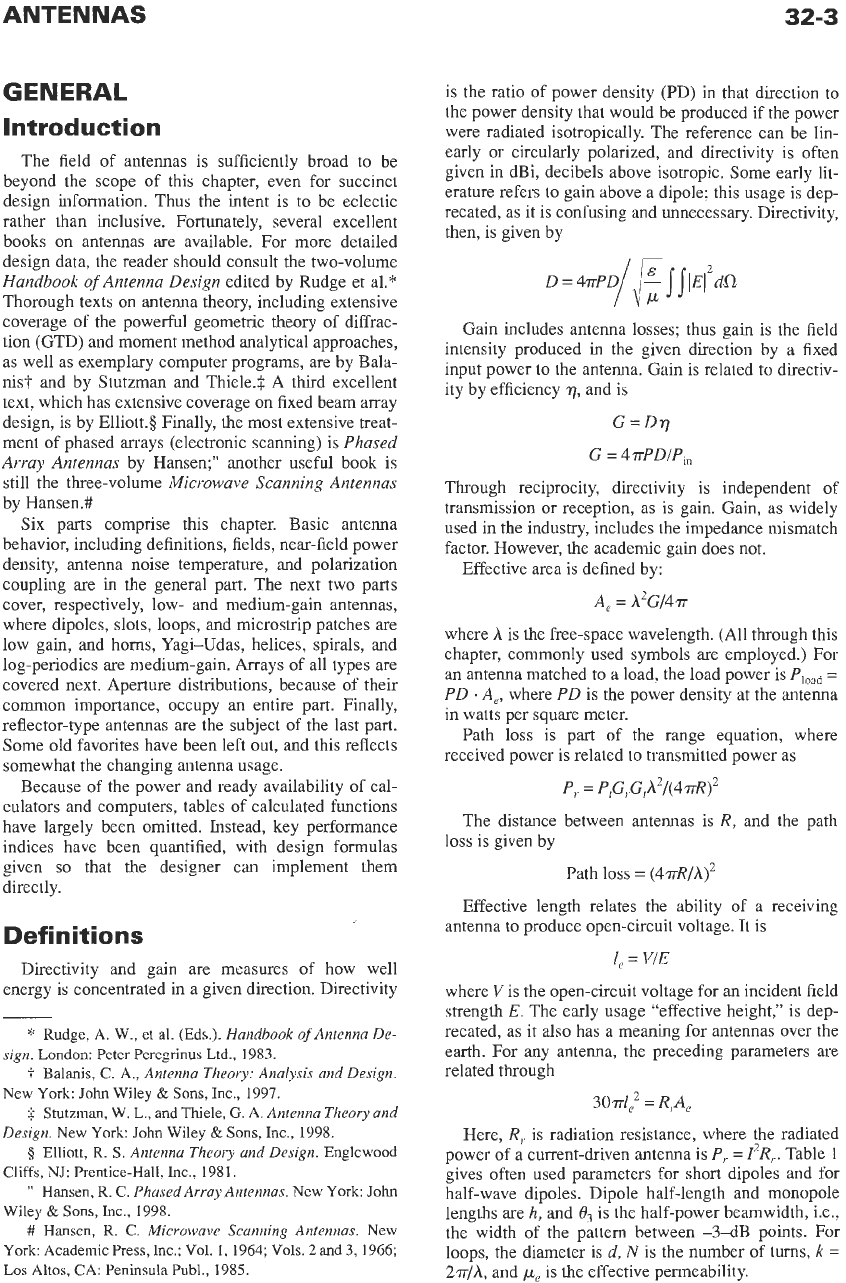
Field regions must be defined carefully, as the early
optical terms are inadequate for modem antennas. The
terms Fraunhofer and Fresnel, which refer to specific
field integral approximations in optics, are obsolete
and deprecated. For example, with focused antennas, a
Fraunhofer-type pattern may exist well within the
usual
D2/A
near-far field boundary distance, while a
Fresnel-type field may exist for smaller and for larger
distances. Some antennas have
no
Fraunhofer-type
fields anywhere, as they have no phase center, e.g.,
some horns and annular slots. Finally, the Fresnel
approximation itself
is
unambiguous only in one
dimension; for
the
more common and useful area
sources, the Fresnel results vary widely with coordi-
nate system and formulation.*
Thus, the following definitions have evolved. Space
is
divided into three regions as follows. That region of
space immediately surrounding the antenna in which
the reactive components predominate is known as the
reactive near-field region.
The size of this region var-
ies for different antennas. For most antennas, however,
the outer limit is
on
the order of a few wavelengths or
less. For the particular case of an electrically small
*
Hansen,
R.
C.
Microwave Scanning Antennas.
New
York
Academic
Press,
Inc.:
1964,
Vol.
1,
Chapter
1;
Los Al-
tos,
CA
Peninsula Publ.,
1985.
dipole, the reactive field predominates to a distance of
approximately
A/2.ir,
where the radiating and reactive
fields are equal. Beyond the reactive near-field region,
the radiating field predominates. The radiating region
is divided into two subregions, the
radiating near-field
region
and the
far-field region.
In
the radiating near-
field region, the relative angular distribution of the
field (the usual radiation pattern) is dependent on the
distance from the antenna. The reason for this behavior
is twofold: the relative phase relationship of field con-
tributions from different elements of the antenna
changes with distance, and the relative amplitudes of
these field contributions also change with distance. As
the observation point in space moves away from the
antenna, the amplitude of the field first oscillates and
then decays monotonically. This variation in the limit
is given by the reciprocal of the first power of distance.
Furthermore, the relative phase and amplitude rela-
tionships between the field contributions from differ-
ent elements of the antenna asymptotically approach a
fixed relationship, and the relative angular distribution
of
the field becomes independent of the distance. This
occurs in the far-field region; patterns are essentially
independent of distance. For most antennas, the transi-
tion distance is
D2
/A,
where
D
is the width of the
equivalent uniformly excited aperture. Precision gain
measurements or measurements
of
nulls may require a
distance of
2D2/A
or more. Low-sidelobe antennas will
require multiples of
D2/A,
depending on the sidelobe
level and allowable error.? Fig.
1
shows the reactive
near-field boundary at
R
=
A
and the
D2/A
far-field
boundary for several planar apertures.
Small
Antennas
Antennas that are small in wavelength are conceptu-
ally simple, and difficult to use, as will appear below.
It has been observed by Wheeler3 that all small anten-
nas are dipoles, loops, or combinations
of
these two
canonical types. When the dipole
(or
monopole over a
large ground plane) is short, the current is essentially
?
Hansen,
R. C.
PhasedArray Antennas.
New
York:
John
Wiley
&
Sons, Inc.,
1998.
$
Wheeler,
H.
A.
“Fundamental Limitations
of
Small
AI-
tennas.”
Proc.
IRE,
Vol.
35,
December
1947,
pp.
1479-1484.
Wheeler,
H.
A.
“Small Antennas.”
Trans.
IEEE, Vol.
AP-23,
July
1975,
pp.
462469.
ANTENNAS
32-5
100
2
10
1
01
10
10
100
R/D
Fig. 1. Field regions.
linear from feed to end, and the fields produced, when
the dipole is along the z-axis of a standard spherical
coordinate system, are
E,
=
j
6Q~hI~e-’~’-
sin
%/rA,
Ha
=
-jhIoeikr
sin
W2rh
The radiation resistance is
R,
=
20k2h2,
where
k
=
2w/A
and
h
is the dipole half-length. Similarly, a small
loop of diameter
d
carries essentially a constant cur-
rent, and the fields with the loop axis along
z
are
analo-
E,
=
3Qdd2I0e-jk’
sin%/rA2
H,
=
-dd2I0eqkr
sin%/4rA2
gously
The radiation resistance is given by:
R,.
=
(5J4)dN2k4d4p2,
See the section
on
low-gain antennas for details of
pe.
When
h
<<A
or
d<<h,
the radiation resistance is
very small, often smaller than the loss resistance of the
conductors. Efficiency then can be small, and although
the directivity is
1.5,
the gain is also small. Reactance,
on
the other hand, is high; for short dipoles it varies as
llkh,
whereas for small loops it varies as
-kd.
The
Q
is
therefore high, and the bandwidth, which is approxi-
mately
(h/h13
for
Q
>>
1,
is small. It is useful
to
know
what bandwidth can be achieved; the Wheeler papers
referred
to
above give practical answers.
A
theoretical
fundamental limitation was derived by Chu” and
refined by Harringtont and Collin.$ See also Hansen.§
*
Chu,
L.
J.,
“Physical Limitations of Omnidirectional
Antennas.”
J.
Appl.
Phys,
Vol.
19, December 1948,
pp.
1163-
1175.
i.
Harrington,
R.
F. “Effect of Antenna Size on Gain,
Bandwidth, and Efficiency.”
J.
Res.
Nat. Bur. Stand.,
Vol.
64D, January-February 1960,
pp.
1-12.
$
Collin,
R.
E.
“Evaluation of Antenna
Q.”
Trans. ZEEE,
0
Hansen,
R.
C. “Fundamental Limitations in Antennas.”
Vol.
AP-12,
January
1964,
pp.
23-27.
Proc. ZEEE,
Vol.
69, February 1981,
pp.
170-182.
for a discussion of fundamental limitations in anten-
nas. Since any radiating field can be written as a
sum
of spherical modes, the antenna, of whatever type it
happens to be, is enclosed
in
a sphere of radius
a.
The
radiated power can be calculated from propagating
modes within the sphere.
All
modes contribute to the
reactive power. When the sphere is sufficiently large
to
support several propagating modes, this approach is of
little value because
the
modal coefficients are difficult
to calculate. With only one propagating mode, the
radiated power arises primarily from that mode. The
utility of the Chu work becomes apparent when the
sphere is
too
small to allow a propagating mode; all
modes are then evanescent (below cutoff), and the
Q
becomes large, as the evanescent modes contribute lit-
tle real power. Note that, unlike the case of a closed
waveguide, there is a real part of each evanescent
mode. Each mode has a Q based
on
the ratio of stored
energy to radiated energy, and the Q rises rapidly when
kr
drops below the mode number. For all modes well
below cutoff, the result is
Q
=
(1
+
k2a2)/[k3a3]
When the antenna contains loss, the
Q
is reduced by
the efficiency,
r].
Fig.
2
gives fundamental limitation
curves for several values of efficiency. This
Q
is for the
100
50
20
10
9
5
2
1
.1
.3
.5
.7
ka
.9
1.1
1.3
1.5
Fig. 2. Cbu-Harrington fundamental limitations for single-
mode antenna,
various
efficiencies.
lowest TM mode. When both a TM mode and a TE
mode are excited, the value of
Q
is halved. The impor-
tance of the Chu result is that it relates the lowest
achievable
Q
to the maximum dimension of an electri-
cally small antenna, and this result is independent of
the
art
that is used to construct the antenna within the
hypothetical sphere, except in determining whether a
pure TE or pure TM mode, or both, is excited. Since
the
Q
grows rapidly (inverse cube) as size decreases,
this indeed represents a fundamental limit that has
only been approached but never equaled, much less
exceeded. Bandwidth is derived from
Q
by assuming
that the antenna equivalent is a resonant circuit with
fixed values. Then the fractional bandwidth is
=
1/Q
fupper
-
fiower
fcetlter
Bandwidth
=
A
matched load
is
not included here, but use of it
halves the
Q.
For
Q
>>
1
this relationship is meaning-
ful, as the fixed resonant circuit is a good approxima-
tion to the antenna. But for
Q
<
2,
the representation is
no longer accurate. However, the curves
are
still useful
for low
Q
even though imprecise. Since most small
antennas are loops or dipoles, which do not use the
spherical volume efficiently, an octave antenna is
large, often larger than h/2.
Antenna bandwidth can be increased by use of one
or more matching networks. The maximum improve-
ment possible was derived by Fano, and his results
have been implemented by Matthaei et
al.*
From their
formulas, the bandwidth improvement factors for
VSWR
=
2
and for the half-power case are as shown in
Table
2.
Electrically small antennas can be broadbanded by
introducing loss as indicated,? or by utilization of a
large mismatch.
A
small loop with a very low-imped-
ance preamplifier at its terminals or a short monopole
(dipole) with a high-impedance preamplifier at its ter-
minals is called an “aperiodic loop” or “aperiodic
TABLE 2. BANDWIDTH
INCREASE
USNG
N
MATCHING SECTIONS
N
v=
2
Half-Power
1 2.3094 2.0301
2 2.8596 2.4563
3 3.1435 2.6772
ca
3.8128 3.2049
*
Matthaei,
G.
L.,
Young,
L., and Jones,
E.
M.
T.
Micro-
wave Filters, Impedance-Matching Networks, and Coupling
Structures.
McGraw-Hill,
1964.
t
Kanda,
M.
“A Relatively
Short
Cylindrical Broadband
Antenna with Tapered Resistive Loading for Picosecond
Pulse Measurements.”
Trans,
IEEE,
Vol.
AF-26,
May
1978,
pp.
439-447.
monopole.” The term “integrated antenna” has been
used, but it is confusing and is now obsolete. If the
amplifier impedance is much larger than the monopole
reactance at the lowest frequency of interest, the out-
put signal is nearly constant over a bandwidth of one
or more octaves. The large mismatch reduces the sig-
nal and external noise. Aperiodic antennas
are
useful at
those frequencies where the external noise is
so
large
that even after the large mismatch loss the antenna
noise is still larger than the preamp noise; thus the sys-
tem is external-noise limited.
Let
the ratio of preamp
input resistance to lowest antenna reactance be
a
=
R/X,,
and use
F,,
as the ratio of external antenna noise tem-
perature to
To
=
290
K,
and
FN
as the preamp noise fig-
ure.
A
key system performance factor,
?,
is the ratio
of
actual
s/n
to
s/n
if the system were external-noise lim-
ited. That is,
y
determines
s/n
degradation compared to
a narrow-band matched antenna-preamp system at fre-
quency
f.
The
sln
degradation factor for a monopole
that is short over the band of interest is$
In
this result,
A
=
ln(h/a)
-
1,
and
h
and
a
are the
monopole length and radius. Even with
FN
in
the 2-dB
range, there can be significant
sln
degradation in using
an aperiodic monopole unless the upper frequency
is
close to the lower,
fi.
Superconducting
Antennas
High
T,
superconducting materials offer advantages
for millimeter arrays, both waveguide and microstrip
types. For superdirective arrays, and for electrically
small dipole antennas, efficiency improvements are
significant only when the radiation resistance is such
that the
Q
is
unacceptably high, typically greater than
1000.
However, these antennas have low radiation
resistance and high reactance which present a very
high
VSWR.
A
transmission-line match or lumped cir-
cuit with matched loss
L
has an apparent
loss L,
that is
greatly increased due
to
the
VSWR
or
K
La
=
[(V+
1yL2
-
(V-
1)2]/4vL
Thus, the superconducting material is needed in the
matching networks. Electrically small loop antennas
can realize efficiency improvements,
but
without the
leavening effect of loss resistance the
Q
is often unus-
ably high. For a review of superconducting antennas,
see Hansen.3
$
Radjy,
A.
H., and Hansen, R.
C.
“S/N
Performance
of
Aperiodic Monopoles.”
Trans.
IEEE,
Val.
AP-27,
March
1979,
pp.
259-261.
Hansen,
R.
C. “Superconducting Antennas.”
Trans.
IEEE,
Val.
AES-26,
March
1990,
pp.
345-355.
ANTENNAS
32-7
1
10
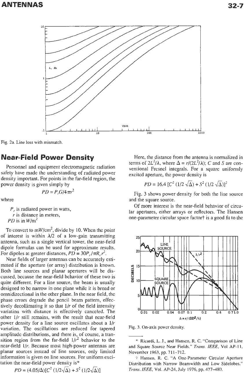
Fig. 2a. Line
loss
with mismatch.
Near-Field Power Density
Personnel and equipment electromagnetic radiation
safety have made the understanding of radiated power
density important. For points in the far-field region, the
power density is given simply by
PD
=
P,.G/4m2
where
P,
is radiated power in watts,
r
is distance in meters,
PD
is in w/m2
To
convert
to
mW/cm2, divide by
10.
When the point
of interest is within
A/2
of a low-gain transmitting
antenna, such as a single vertical tower, the near-field
dipole formulas can be used for approximate results.
For dipoles
at
greater distances,
PD
=
30P,/.rrR,.r2.
Near fields of larger antennas can be accurately esti-
mated if the aperture (or array) distribution is known.
Both line sources and planar apertures will be dis-
cussed, because the near-field behavior of these two is
quite different. For a line source, the beam is usually
designed to be narrow in one plane while it is broad or
omnidirectional
in
the
other plane. In the near field, the
phase errors degrade the pencil beam pattern, effec-
tively decollimating
it
so
that
l/r
of the field intensity
variation with distance is effectively canceled. The
other
l/r
still remains, with the result that near-field
power density for a line source oscillates about a
l/r
variation. The oscillations are reduced for tapered
amplitude distributions, and there is, of course, a tran-
sition region from the far-field
1/r2
behavior to the
near-field
l/r.
Because most high-power antennas are
planar sources instead
of
line sources,
only
limited
information is given on line sources. For uniform exci-
tation the near-field power density is*
PD
=
(4.05/A)[C2
(1/2&)
+
S2
(1/2&)]
I
loo
Here, the distance from the antenna
is
normalized in
terms
of
2L2/A,
where
A
=
r/(2L2/A);
C
and
S
are
con-
ventional Fresnel integrals. For a square uniformly
excited aperture, the power density is
PD
=
16.4
[C2
(1/2
4)
+
S2
(1/2
&)I2
Fig.
3
shows power density for both the line source
and the square source.
Of more interest is the near-field behavior of circu-
lar apertures, either arrays or reflectors. The Hansen
one-parameter circular space factor? is a good fit
to
the
A
=
r/
(zDZ/x)
Fig.
3. On-axis power density.
*
Ricardi, L.
J.,
and Hansen, R.
C.
“Comparison
of
Line
and Square
Source
Near Fields.”
Trans.
IEEE,
Vol Ap-11,
November 1963, pp. 711-712.
t
Hansen, R.
C.
“A One-Parameter
Circular
Aperture
Distribution with Narrow Beamwidth and Low Sidelobes.”
Trans.
IEEE,
Vol. AP-24,
July
1976, pp. 477480.