Middleton W.M. (ed.) Reference Data for Engineers: Radio, Electronics, Computer and Communications
Подождите немного. Документ загружается.


12-2
REFERENCE
DATA
FOR ENGINEERS
Network Analysis
12 -1
3
Sources
Receivers
Test Sets
Displays and Output
Six-Port Network
Error Correction
Frequency and Time-Domain Relationships
Large-Signal Measurements
Signal Analysis
12-17
Amplitude Measurement Range
Signal-Analysis Characteristics as Determined by the
IF Filter, Detector, and Video Amplifier
Time and Frequency Measurement
12-20
Time Measurement
Frequency Measurement
Frequency and Time-Interval Analysis
RF and Microwave Power Measurements
12-24
Thermistor Sensors
Thermal Converters
Thermocouple Sensors
Diode Sensors
Power-Measurement Definitions
Microwave-Link Analysis
12-26
Insertion
Loss
or Gain
Amplitude Response
Envelope-Delay Distortion (EDD)
Measurement
of
Group-Delay Distortion
Return Loss
Measurement of Return Loss
Baseband Measurements
Carrier/Noise Measurement
Diagnostic Measurements and System Performance
Computer Control
of
Instruments
12-33
IEEE
488.1
or IEC 625-
1
General Purpose Interface
IEEE 488.2 or IEC 625-2
Standard Commands for Programmable Instruments
Bus
(GPIB)
WPI)
Electromagnetic Compatibility
,
Interference, and
Susceptibility
12-35
EMUEMUEMS
Regulations
EMVEMS Measurements

MEASUREMENTS AND ANALYSIS
12-3
The aim of this chapter is to provide a condensed
description of methods of electronic measurements.
Science and technology would indeed be vague without
the ability to measure. Lord Kelvin cautioned that
“Knowledge not expressible in numbers is of a meager
and unsatisfactory kind”; he was identifying an essen-
tial aspect of scientific knowledge.
In the past, measurements of voltage, frequency,
impedance, or power were made by using bridges or
substitution methods with prototype standards derived
from primary standards. Now, using digital techniques,
one can create signals with precise voltage, frequency,
and phase and can measure signals with the same
precision. Many measurements are now made by stimu-
lating the network or system with a precise signal,
measuring the response, and using a microprocessor to
compute the impedance, gain, phase, or other required
results.
Another method for determination of measured
quantities uses the technique of ratio measurements.
For example, the complex ratio of
EII
can be deter-
mined very precisely for a given frequency; then a
microprocessor instantaneously calculates the imped-
ance or response. In addition, the sequential steps of
measurements, computation, and final display can also
be controlled by the same microprocessor. Touch and
read instruments were created by these technologies.
These measurements topics will be covered:
Impedance
Networks
Signals
Time and Frequency
Power
Microwave Links
IEEE
488
Data
Bus
EMYEMUEMS
It is assumed that the reader is already familiar with
such fundamental topics as voltage, current, gain,
phase, distortion, etc. Specialized measurements for
linear systems, digital signals, time domains, fields,
magnetics, etc., are left for specialized publications.
(Some chapters in this book covering specialized topics
do contain information on the associated measure-
ments.)
IMPEDANCE BRIDGES
In the diagrams
of
bridges in this section, the source
(generator) and the detector (headphones) may be
interchanged as dictated by the location of grounds. For
all but the lowest frequencies, a shielded transformer is
required at either the input or output (but not usually
both) terminals of the bridge. The detector is chosen
according to the frequency of the source. When insensi-
tivity
of
the ear makes direct use of headphones
impractical, a simple radio receiver or its equivalent is
essential. Some selectivity is desirable to discriminate
against harmonics, for the bridge is often frequency
sensitive. The source may be modulated to obtain an
audible signal, but greater sensitivity and discrimina-
tion against interference are obtained by the use of a
continuous-wave source and a heterodyne detector.
An
oscilloscope is sometimes preferred for observing nulls.
In this case,
it
is convenient to have an audible output
signal available for the preliminary setup and for
locating trouble, since much can be deduced from the
quality
of
the audible signal that would not be apparent
from observation of amplitude only.
Fundamental Alternating-
Current or Wheatstone Bridge
Refer to Fig.
1.
The balance condition is
Z,
=
Z,Z,/Z,.
Maximum sensitivity exists when
Z,
is the
conjugate of the bridge output impedance and
Z,
is
the
conjugate of its input impedance. Greatest sensitivity
exists when the bridge arms are equal; for example, for
resistive arms
Zd
=
z,
=
z,
=
z,
=
z,
=
z,
Wagner Ground Connection
None of the bridge elements (Fig.
2)
is grounded
directly. First balance the bridge with the switch to
B.
Throw the switch to
G,
and rebalance by means of
R
and
C.
Recheck the bridge balance and repeat as
required. The capacitor balance
C
is
necessary only
when the frequency
is
above the audio range. The
transformer may have only a single shield as shown,
with the capacitance of the secondary to the shield kept
to a minimum.
GENERATOR
Fig.
1.
Fundamental
ac
bridge.

12-4
REFERENCE
DATA
FOR ENGINEERS
Fig.
2.
Wagner
ground
connection
Capacitor Balance
A
capacitor balance is useful when one point
of
the
bridge must be grounded directly and only a simple
shielded transformer is used (Fig.
3).
Balance the
bridge, then open the two arms at
P
and
Q.
Rebalance
by auxiliary capacitor
C.
Close
P
and
Q
and check the
balance.
*
Fig.
4.
Series-resistance-capacitance bridge.
Series
-
Resistance- Capacitance
Bridge
In the bridge of Fig.
4:
Wien Bridge
In
the bridge of Fig.
5:
For measurement of frequency,
or
in
a frequency-
selective application, if we make
C,
=
C,,
Rx
=
R,,
and
R,
=
2R,,
then
f=
(2K,R,)-'
4
Fig.
5.
Wien bridge.
Fig.
3.
Capacitor balance.

MEASUREMENTS AND ANALYSIS
12-5
Fig.
6.
Owen bridge.
Owen Bridge
In the bridge
of
Fig.
6:
I;
Fig.
8.
Maxwell bridge.
Resonance Bridge
In the bridge of Fig.
7:
W2LC
=
1
Maxwell Bridge
In the bridge
of
Fig.
8:
L,
=
R,RbC,
R,
=
RaRb/R,
Q,
=
w(L,/R,)
=
wC,R,
-@
Hay Bridge
The bridge of Fig.
9
is
for the measurement
of
large
inductance.
L,
=
R,RbC,/(I
i-
W2c:R,2)
Q,
=
oL,/R,
=
(oC,R,)-'
Schering Bridge
In the bridge
of
Fig.
10:
C,
=
C,Rb/R,
l/Q,
=
WC,R,
=
WCbRb
Substitution Method for High
Impedances
Refer
to
Fig.
1
1.
Initial balance (unknown terminals
x
-
n
open):
C,
'
and
R,
'
Fig.
9.
Hay bridge.
Fig.
7.
Resonance bridge.

12-6
REFERENCE DATA FOR ENGINEERS
*
Fig.
10.
Schering bridge.
Final balance (unknown connected to
x
-
x):
C,"
and
R,"
Then when
R,
>
IOiwC,',
there results, with error
<
1
percent
c,
=
C,'
-
C,"
The parallel resistance is
R,
=
[w*C,'~(R,'
-
R,")]-'
If unknown
is
an inductor
L,
=
-(02c,)-'
=
[w2(Cs"
-
Cs')]-'
I
fiJ
Measurement
With
Capacitor in
Series With Unknown
Refer
to
Fig.
12.
Initial balance (unknown terminals
x
-
x
short-
circuited):
C,
'
and
R,
'
Final balance
(x
-
x
unshorted):
C,"
and-
R,"
Then
R,
=
(R,"
-
R,')Ra/Rb
RbC,'C,"
c,
=
Ra(C,'
-
C,")
When
C,"
>
C,'
Measurement
of
Direct
Capacitance
Refer to Fig.
13.
Connection of
N
to
N'
places
C,,
across the detector
and
C,
across
Rb,
which requires
only
a small readjust-
ment of
R,.
Fig.
11.
Substitution method.
Fig.
12.
Measurement with capacitor in series with unknowjn.
MEASUREMENTS AND ANALYSIS
12-7
I”,,
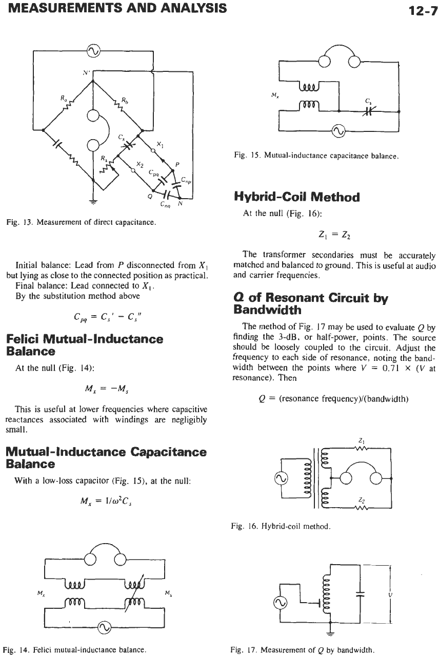
Fig. 13. Measurement
of
direct capacitance.
Initial balance: Lead from
P
disconnected from
X,
but lying as close to the connected position as practical.
Final balance: Lead connected to
XI.
By the substitution method above
cp4
=
C,’
-
C,”
Felici Mutual- Inductance
Balance
At the null (Fig.
14):
M,
=
-M,
This is useful at lower frequencies where capacitive
reactances associated with windings are negligibly
small.
Mutual-Inductance Capacitance
Balance
With a low-loss capacitor
(Fig.
15),
at the null:
M,
=
l/02C,
Fig.
15.
Mutual-inductance capacitance balance.
Hybrid-Coil Method
At the null (Fig.
16):
z,
=
z,
The transformer secondaries must be accurately
matched and balanced to ground. This is useful at audio
and carrier frequencies.
0
of
Resonant Circuit by
Bandwidth
The method of Fig.
17
may be used to evaluate
Q
by
finding the 3-dB, or half-power, points. The source
should be loosely coupled to the circuit. Adjust the
frequency to each side of resonance, noting the band-
width between the points where
V
=
0.71
X
(V
at
resonance). Then
Q
=
(resonance frequency)/(bandwidth)
Fig.
16.
Hybrid-coil method.
n
Fig.
14.
Felici mutual-inductance balance.
+
Fig.
17.
Measurement
of
Q
by bandwidth.

12-8
REFERENCE
DATA
FOR
ENGINEERS
HI
HI
Fig.
18.
Q
meter.
0
Meter (Hewlett-Packard
4342A)
Refer to Fig.
18.
In
this circuit,
T,
is a wideband
transformer with
n
turns in the primary and one turn in
the secondary. The secondary impedance is
0.001
ohm.
The combination
L,R,Co
represents an unknown coil
plugged into the
COIL
terminals for measurement;
V2
is
a very high impedance voltmeter. With this arrange-
ment,
Q
=
nV21Vl
Correction
of
Q
Reading-The value of
Q
correct-
ed for distributed capacitance
Co
of the coil is given by
Qtrue
=
Q[(c
+
COYCI
where,
Q
=
reading of Q-meter (corrected for internal
C
=
capacitance reading of Q-meter.
Measurement
of
Co
and True L,-The plot
of
llf2
against
C
is a straight line (Fig.
19).
resistors
RI
and
R2
if necessary),
L,
=
true inductance
1
lP
Co
=
negative intercept
fo
=
natural frequency of coil
When only two readings are taken and
fi
lfi
=
2.00
Co
=
(C2
-
4Cl)/3
With values in microhenrys; megahertz, and picofarads
L,
=
19
000/fi2(C2
-
C,)
Measurement
of
Admittance-
An
initial reading,
C’Q’,
is taken as in Fig.
20A
(LR,
is any suitable coil).
For
the final reading, C”Q” (Fig.
20B):
1IZ
=
Y
=
G
+
jB
=
IIR,
+
joC
Then
l/Q
=
G/wC
=
C‘IC(1OOOlQ”
-
IOOOIQ’)
X
If
Z
is inductive
C”
>
C’
Measurement
of
Impedances
Lower
Than
Those Directly Measurable-For the initial read-
ing, C’Q‘, the
CAPACITOR
terminals are open (Fig.
21A).
On
the second reading, CI‘Q‘’, a capacitive divider,
c,cb
(Fig.
21B),
is connected to the
CAPACITOR
terminals.
P
0
RP
a
(Aj
lnlllal
reodlng
L-%+
Fig.
19.
Plot
of
C
and
Ilf’.
(B)
Nnal
reodlng.
Fig.
20.
Measurement
of
admittance.

MEASUREMENTS AND ANALYSIS
12-9
+
[A)
Initral
reading
Y”
-3
4
[E)
Copocrtiue
drulder.
(C)
Connectlon
of
unknown
Fig.
21.
Measurement
of
low
impedances.
For the final reading,
C’”Q’”,
the unknown is con-
nected to
x
-
x
(Fig. 21c). Admittances
Y,
and
Yb
are
Y,
=
G,
-+
jwC,
Yb
=
+
jWCb
with G, and
Gb
not shown in the diagrams.
Then the unknown impedance is
z
=
[Y,/(Y,
+
Y,)]2(Y”’
-
Y’7-1
-
(Y,
+
Y,)-I
ohms
where, with capacitance in picofarads and
o
=
2n
X
frequency
in
megahertz
(Y”’
-
YTI
-
106/w
-
C‘(lOOO/Q”’
-
lOOO/Q”)
X
+
j(C“
-
C‘”)
Usually
G,
and
Gb
may be neglected; then there
results
For
many measurements,
C,
may be
100
picofarads.
Capacitance
Cb
=
0
for very low values of
Z
and for
highly reactive values
of
Z.
For
unknowns that are
principally resistive and of low or medium value,
C,
may take sizes up
to
300
to
500
picofarads. When
Cb
=
0
Z
=
(Y”’
-
Y”)-l
+
j(106/wC,)
ohms
and the “second” reading above becomes the “ini-
tial,” with
C’
=
C”
in
the equations.
Measurement
of
Coupling Coefficient
of
Loose-
ly
Coupled Coils-The coefficient of coupling
k
=
M/(L,L2)1’2
between two high-Q coils can be obtained by measuring
the inductance
L
with
SI
closed and again with
S,
open
(Fig. 22). From these two measurements
k
=
(1
-
Lclosed/Lopen)li2
When the coil self-inductances are known,
a
mea-
surement
of
L,
and
Lb
(Fig. 23) yields
k
=
(L,
-
Lb)/4(LIL2)”’
If
L,
=
L2
k
=
(L,
-
Lb)/(L,
$-
L,)
Neither
of
the above methods provides adequate
precision when two high-Q coils are
only
about critical-
ly coupled.
In
that case, the Q of each coil is measured
with the other coil open-circuited. Then the coupled
coils
(L,
R
,
and
L2R2)
and a low-loss adjustable capaci-
tor
(C,)
are connected to the Q-meter as shown in Fig.
24,
Cz
is disconnected, and
C
is
adjusted to maximize
Fig.
22.
Method
of
determining
coefficient
of
coupling
between
two
coils.

12-10
REFERENCE DATA FOR ENGINEERS
Lo-
Fig.
23.
Method of determining coefficient of coupling when
self-inductances
are
known.
R1
R"
Fig.
24.
Method
of
determining coefficient
of
coupling when
coils
are
only about critically coupled.
the Q-meter reading;
C2
is then connected and adjusted
to
minimize the reading. If the final reading is Qo
If the final reading is too small to be read accurately,
Q2 may
be
reduced by inserting a small resistance in
series with
L2R2.
Twin-T Admittance-Measuring
Circuit (General Radio Type
821
-A)
The circuit in Fig.
25
may be used for measuring
admittances in a range somewhat exceeding
400
kilo-
hertz
to
40
megahertz. It is applicable to the special
measuring techniques described above for the Q-meter.
Conditions for a null in the output
are
With the unknown disconnected, call the initial
balance
cb'
and
Cg'.
With the unknown connected, the
final balance is
Cb''
and
C,".
Then the components of
the unknown,
Y
=
G
+
jwC,
are
c
=
cb'
-
Cb"
G
=
(Ro2CIC2/C,)(C,"
-
C,')
Ratio-Arm Bridges
(Wayne Kerr)*
Transformer ratio-arm bridges can be designed
to
operate at radio frequencies up to about
250
MHz.
Beyond that point, other forms of bridges based
on
transmission lines become practicable.
Fig.
26
illustrates a practical circuit for a bridge
*
From
Calvert, R.
The Transformer
Ratio-Arm
Bridge.
Bognor
Regis, Sussex, England: Wayne
Kerr
Co. Ltd.
Fig.
25.
Twin-T admittance-measuring circuit.
G
STANDARD
rn
RF
gT
I
I
CONNECTING
7
BLOCKS
I
q-+
Fig.
26.
Ratio-arm bridge.
MEASUREMENTS AND ANALYSIS
12-1
1
capable of operating at frequencies up to
100
MHz.
The
transformers are formed by winding thin silver tapes
onto ferrite
or
ferrous-dust ring cores, which are mount-
ed inside individual screening cans. Drums of low-
inductance resistors forming fixed conductance stan-
dards are arranged
to
engage with spring contacts. A
variable conductance for interpolation is formed by
means of resistor
R,
which is fed with a voltage derived
from a resistive potential divider,
P.
Radio-frequency bridge measurements require that
considerable care should be taken in setting
up
the
apparatus. Any leakage of power from the source to the
detector that bypasses the bridge network will give
errors.
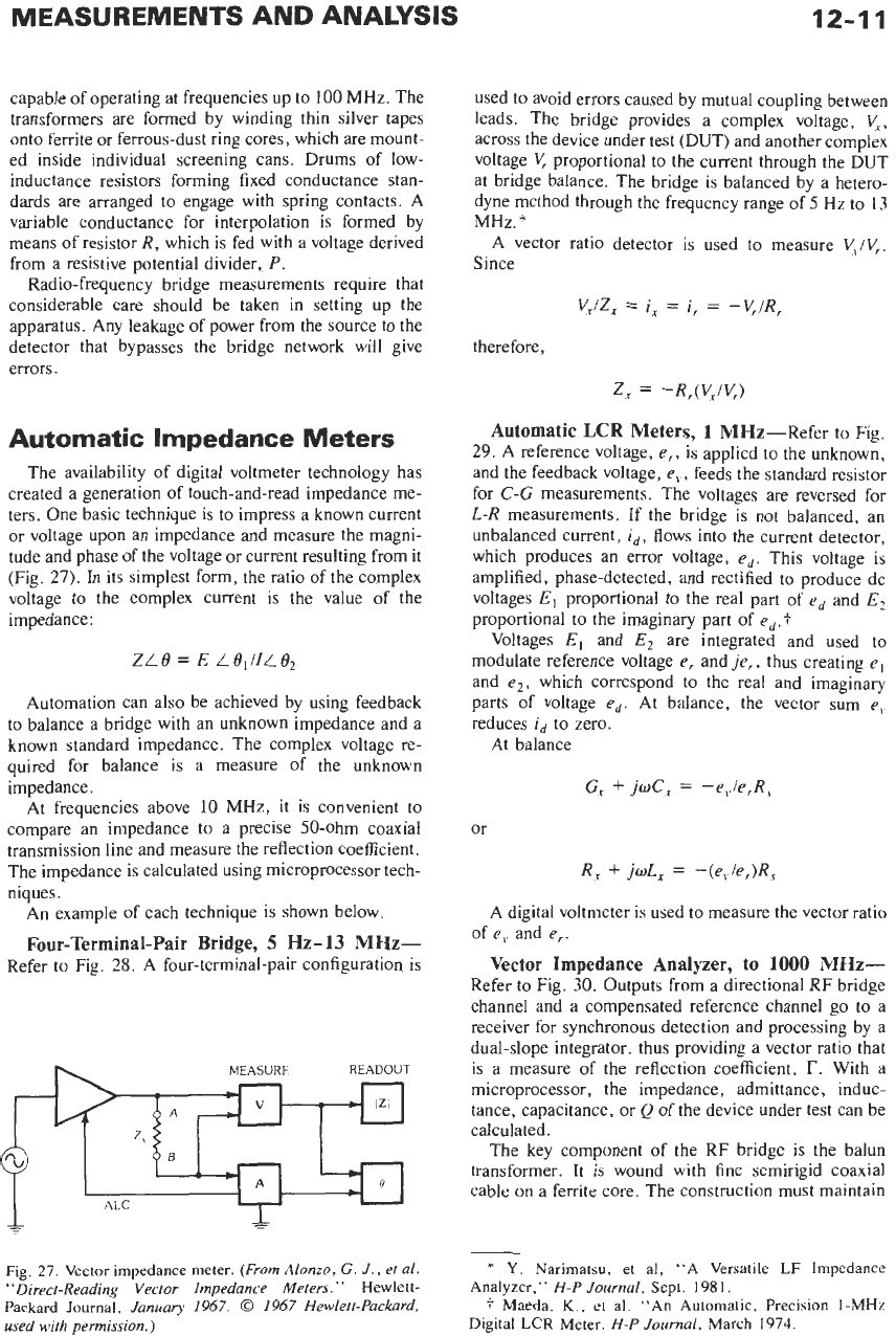
Automatic Impedance Meters
The availability of digital voltmeter technology has
created a generation of touch-and-read impedance me-
ters. One basic technique is
to
impress a known current
or
voltage upon an impedance and measure the magni-
tude and phase of the voltage
or
current resulting from it
(Fig.
27).
In
its simplest form, the ratio of the complex
voltage to the complex current is the value of the
impedance:
ZL
e
=
E
L
e,
IIL
e2
Automation can also be achieved by using feedback
to balance a bridge with an unknown impedance and a
known standard impedance. The complex voltage re-
quired for balance is a measure of the unknown
impedance.
At frequencies above
10
MHz,
it is convenient to
compare an impedance to a precise 50-ohm coaxial
transmission line and measure the reflection coefficient.
The impedance is calculated using microprocessor tech-
niques.
An example of each technique is shown below.
Four-Terminal-Pair Bridge,
5
Hz-13
MHz-
Refer to Fig.
28.
A
four-terminal-pair configuration is
MEASURE
READOUT
used to avoid errors caused by mutual coupling between
leads. The bridge provides a complex voltage,
V‘,
across the device under test (DUT) and another complex
voltage
V,
proportional to the current through the DUT
at bridge balance. The bridge is balanced by a hetero-
dyne method through the frequency range
of
5
Hz
to
13
MHz.*
A
vector ratio detector is used to measure
V,lV,.
Since
V,lZ,
=
i,
=
i,
=
-V,IR,
therefore,
Z,
=
-R,(V,IV,)
Automatic
LCR
Meters,
1
MHz-Refer to Fig.
29.
A reference voltage,
e,,
is applied to the unknown,
and the feedback voltage,
e,,
feeds the standard resistor
for
C-G
measurements. The voltages are reversed for
L-R
measurements. If the bridge is not balanced, an
unbalanced current,
id,
flows into the current detector,
which produces an error voltage,
ed.
This voltage is
amplified, phase-detected, and rectified to produce dc
voltages
E,
proportional to the real part of
ed
and
E?
proportional to the imaginary part of
ed.+
Voltages E, and
E,
are integrated and used to
modulate reference voltage
e,
and
;e,,
thus creating
e,
and
el,
which correspond to the real and imaginary
parts of voltage
ed.
At balance, the vector sum
e,
reduces
id
to zero.
At balance
G,
f
JwC,
=
-e,./e,R,
or
R,
f
jwL,
=
-(e,le,)R,
A digital voltmeter is used to measure the vector ratio
of
e,
and
e,.
Vector Impedance Analyzer,
to
1000
MHz-
Refer to Fig.
30.
Outputs from a directional RF bridge
channel and a compensated reference channel go to a
receiver for synchronous detection and processing by a
dual-slope integrator, thus providing a vector ratio that
is a measure of the reflection coefficient,
r.
With a
microprocessor, the impedance, admittance, induc-
tance, capacitance, or
Q
of the device under test can be
calculated.
The key component of the RF bridge is the balun
transformer.
It
is wound with fine semirigid coaxial
cable
on
a ferrite core. The construction must maintain
Fig.
27.
Vector impedance meter.
(From
Alonzo,
G.
J.,
et
al.
“Direct-Reading Vector Impedance Meters.”
Hewlett-
Packard Journal,
January 1967.
0
1967 Hewlett-Packard,
used with permission.)
*
Y.
Narimatsu, et al, “A Versatile
LF
Impedance
f
Maeda,
K.,
et al. “An Automatic, Precision
I-MHz
Analyzer,”
H-P Journal,
Sept.
1981.
Digital
LCR
Meter.
H-P Journal,
March
1974.