Middleton W.M. (ed.) Reference Data for Engineers: Radio, Electronics, Computer and Communications
Подождите немного. Документ загружается.

22-14
REFERENCE
DATA
FOR ENGINEERS
2."
03 10
2
3
5
10
20
30
50
WAVELENGTH
(pm)
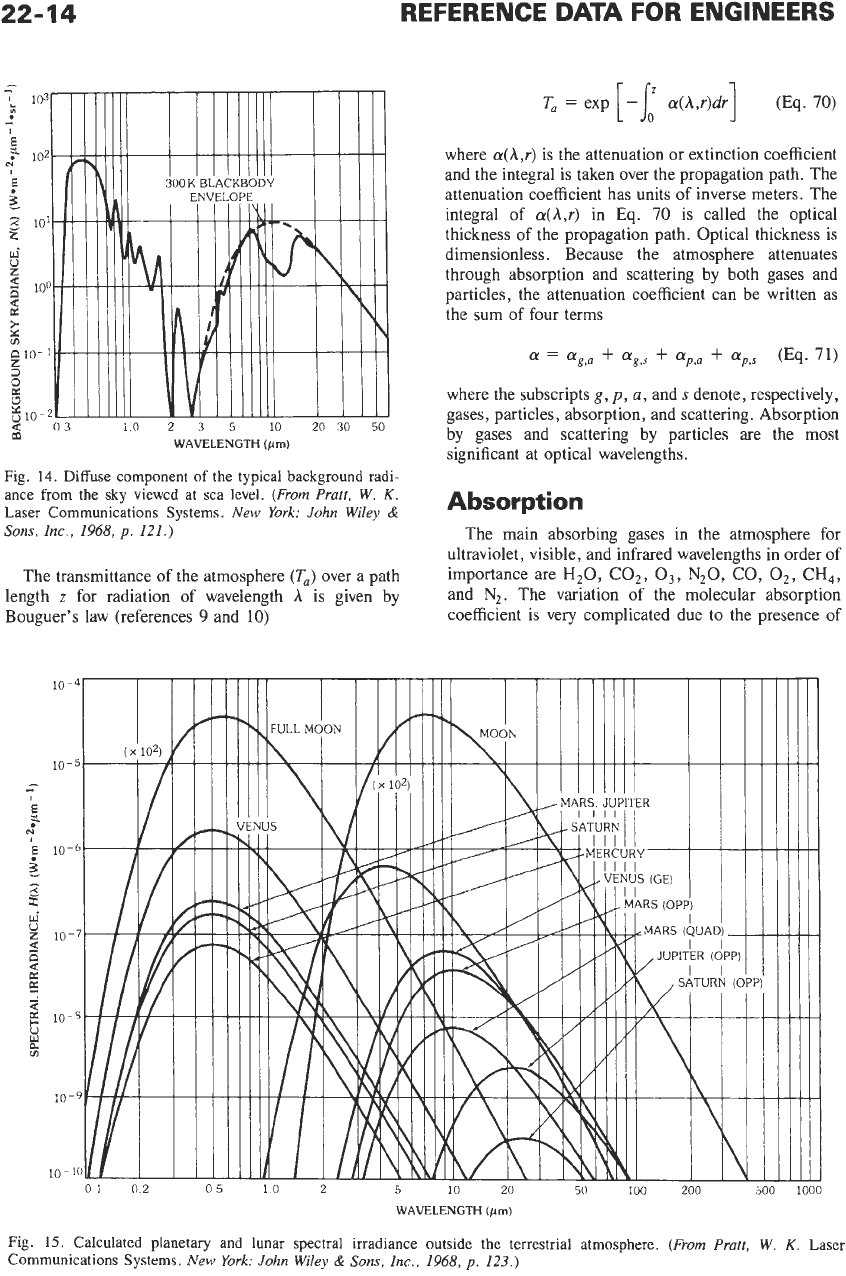
Fig.
14.
Diffuse component
of
the typical background radi-
ance from the sky viewed at sea level.
(From
Prutt,
W.
K.
Laser Communications Systems.
New
York:
John
Wiley
&
Sons,
Inc.,
1968,
p.
121.)
The transmittance of the atmosphere
(T,)
over a path
length
z
for radiation of wavelength
A
is given by
Bouguer's law (references
9
and
10)
where
cu(A,r)
is the attenuation or extinction coefficient
and the integral is taken over the propagation path. The
attenuation coefficient has units
of
inverse meters. The
integral of
cr(A,r)
in
Eq.
70
is called the optical
thickness of the propagation path. Optical thickness
is
dimensionless. Because the atmosphere attenuates
through absorption and scattering by both gases and
particles, the attenuation coefficient can be written as
the sum of four terms
ff
=
ffg,a
+
ffg,s
+
ffp,,
+
up,$
(Eq.
71)
where the subscripts
g,
p,
a,
and
s
denote, respectively,
gases, particles, absorption, and scattering. Absorption
by gases and scattering by particles are the most
significant at optical wavelengths.
Absorption
The main absorbing gases in the atmosphere for
ultraviolet, visible, and infrared wavelengths
in
order of
importance are
H20, COz,
03,
N20,
CO,
02,
CH4,
and
N2.
The variation
of
the molecular absorption
coefficient is very complicated due to the presence of
WAVELENGTH
(pm)
Fig.
15.
Calculated planetary and lunar spectral irradiance outside the terrestrial atmosphere.
(From Prutt,
W.
K.
Laser
Communications Systems.
New
York:
John
Wiley
&
Sons,
Inc.,
1968,
p.
123.)
OPTICAL COMMUNICATIONS
10-
P
E
a
10
U
I
-
N
22-15
10
-
0 02
01
10
WAVELENGTH
(pn)
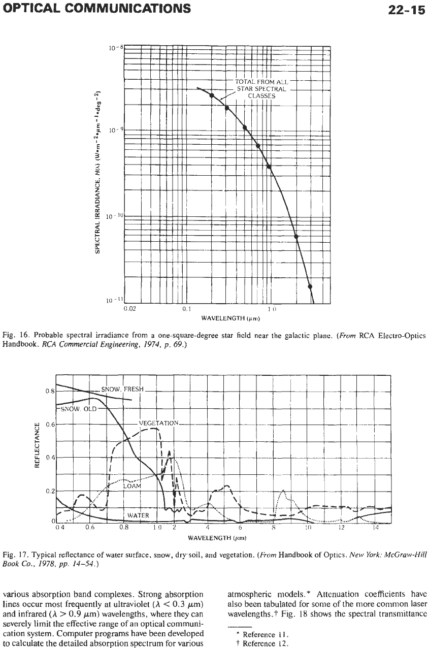
Fig.
16. Probable spectral irradiance from a one-square-degree star field near the galactic plane.
(From
RCA
Electro-Optics
Handbook.
RCA
Commercial Engineering,
1974,
p.
69.)
WAVELENGTH
(pn)
Fig.
17.
Typical reflectance of water surface, snow, drysoil, and vegetation.
(From
Handbook of Optics.
New
York: McGruw-Hill
Book
Co.,
1978,
pp.
14-54.)
various absorption band complexes. Strong absorption
lines occur most frequently at ultraviolet
(A
<
0.3
pm)
and infrared
(A
>
0.9
pm) wavelengths, where they can
severely limit the effective range of an optical communi-
cation system. Computer programs have been developed
to calculate the detailed absorption spectrum for various
atmospheric models.
*
Attenuation coefficients have
also been tabulated for some of the more common laser
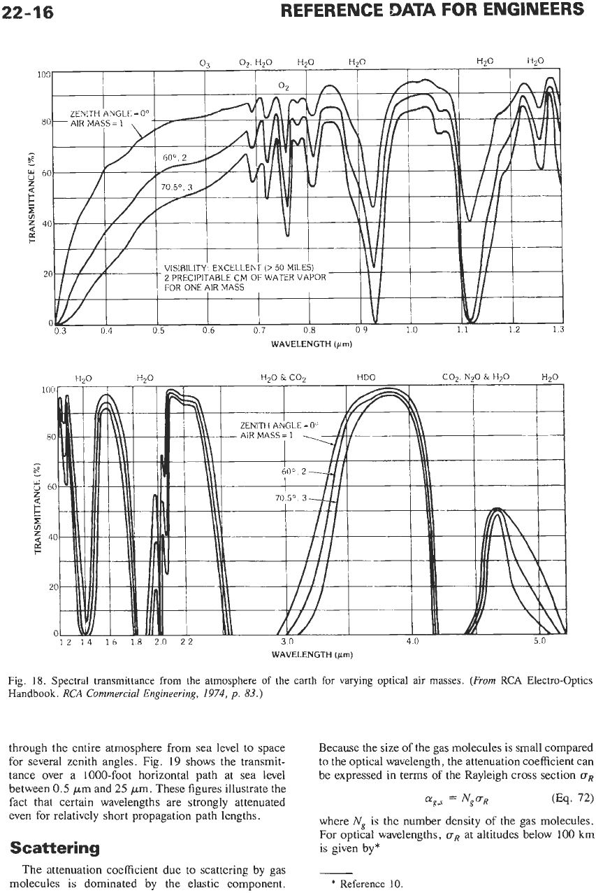
wavelengths.? Fig.
18
shows the spectral transmittance
-
*
Reference 11.
t
Reference 12.
22
WAVELENGTH
(pm)
WAVELENGTH
(pm)
Fig.
18.
Spectral transmittance from the atmosphere
of
the earth for varying optical
air
masses.
(From
RCA Electro-optics
Handbook.
RCA
Commercial Engineering,
1974,
p.
83.)
through the entire atmosphere from sea level to space
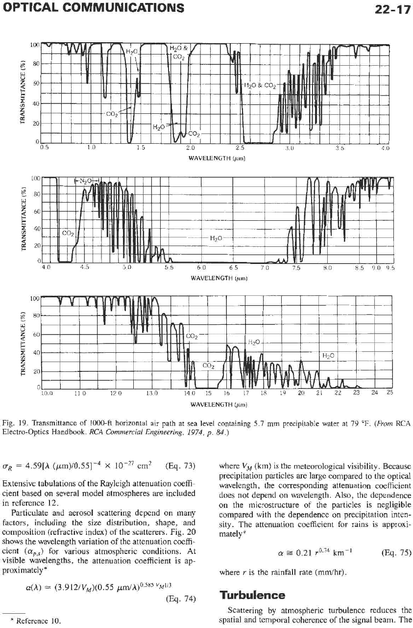
for several zenith angles. Fig.
19
shows the transmit-
tance over a 1000-foot horizontal path at sea level
between 0.5 Fm and
25
pn.
These figures illustrate the
fact that certain wavelengths are strongly attenuated
even for relatively short propagation path lengths.
Scattering
Because the size of the gas molecules is small compared
to the optical wavelength, the attenuation coefficient can
be expressed in terms
of
the Rayleigh cross section
a,
Lyg,s
=
Ng'R
(Eq.
72)
where
N,
is the number density
of
the gas molecules.
For optical wavelengths,
uR
at altitudesbelow
100
km
is given by*
The attenuation coefficient due to scattering by gas
molecules is dominated by the elastic component.
-
*
Reference
10.
OPTICAL COMMUNICATIONS
22-17
100
E
80
w
0
z
60
$
40
z
d
5
e
20
0
05
10
15
20 25
30
35 40
WAVELENGTH
(pm)
100
-
E
80
w
0
2
60
5:
40
m
z
20
0
40
45
50
55
60
65
70 75
80 85
90
95
WAVELENGTH
(pm)
100
-
E
80
w
0
60
$
40
z
20
a
II
II
I
100
11
0
12
0
13
0
140
15
16
17
18
19
20 21 22 23
24
25
WAVELENGTH
(pn)
Fig. 19. Transmittance of 1000-ft horizontal air path
at
sea level containing 5.7
mm
precipitable water at 79
OF.
(From
RCA
Electro-optics Handbook.
RCA
Commercial Engineering,
1974,
p.
84.)
uR
=
4.59[h (/.~m)/0.55]-~
X
cm2
(Eq.
73)
Extensive tabulations of the Rayleigh attenuation coeffi-
cient based on several model atmospheres are included
in reference 12.
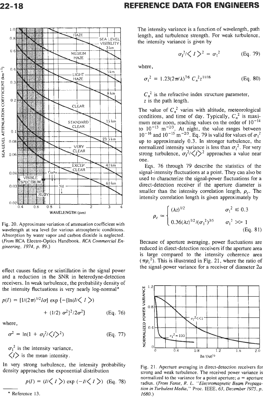
Particulate and aerosol scattering depend on many
factors, including the size distribution, shape, and
composition (refractive index)
of the scatterers. Fig.
20
shows the wavelength variation of the attenuation coeffi-
cient
((Y~,~)
for various atmospheric conditions. At
visible wavelengths, the attenuation coefficient is ap-
proximately*
(~(h)
L-
(3.912/VM)(O.55
/.~rn/A)'.~~~
"~4''~
(Eq. 74)
where
V,
(km) is the meteorological visibility. Because
precipitation particles are large compared to the optical
wavelength, the corresponding attenuation coefficient
does not depend
on
wavelength. Also, the dependence
on the microstructure of the particles
is
negligible
compared with the dependence on precipitation inten-
sity. The attenuation coefficient for rains is approxi-
mately*
(Y
=
0.21
r0.74
km-l
(Eq. 75)
where
r
is the rainfall rate (mdhr).
Turbulence
Scattering by atmospheric turbulence reduces the
spatial and temporal coherence of the signal beam. The
*
Reference
10.
22-18
REFERENCE
DATA
FOR ENGINEERS
Fig.
20.
Approximate variation of attenuation coefficient with
wavelength at sea level for various atmospheric conditions.
Absorption by water vapor and carbon dioxide is neglected.
(From
RCA Electro-optics Handbook.
RCA
Commercial En-
gineering,
1974,
p.
89.)
effect causes fading or scintillation in the signal power
and a reduction in the
SNR
in heterodyne-detection
receivers. In weak turbulence, the probability density of
the intensity fluctuations is very nearly log-normal*
p(~)
=
[I/(~T)’”IUI exp {-[In(I/<
I
>)
+
(1/2)
d]2/2u2}
(Eq.
76)
where,
ut
is the intensity variance,
<Z>
is the mean intensity.
In very strong turbulence, the intensity probability
density approaches the exponential distribution
~(1)
=
(I/<
I
>)
exp
(-I/<
I
>I
(Eq.
78)
*
Reference
13.
The intensity variance
is
a function of wavelength, path
length, and turbulence strength. For weak turbulence,
the intensity variance is given by
u?/<
I
>‘
=
u,2
(Eq.
79)
where,
at2 =
1.23(2~/A)~’~
C:Z”’~~
0%.
80)
C;
is the refractive index structure parameter,
z
is the path length.
The value of
C:
varies with altitude, meteorological
conditions, and time of day. Typically,
C:
is
maxi-
mum near noon, reaching values on the order of
to m-a3. At night, the value ranges between
m-u3.
Eq.
79 is valid for values of
uI2
up to approximately
0.3.
In stronger turbulence, the
normalized intensity variance is less than
u12.
For very
strong turbulence,
U?/<Z>~
approaches a value near
one.
Eqs.
76 through 79 describe the statistics of the
signal-intensity fluctuations at a point. They can also be
used to characterize the signal-power fluctuations for a
direct-detection receiver if the aperture diameter is
smaller than the intensity correlation length,
pc.
The
intensity correlation length is given approximately by
and
(Az)“~
uI2
5
0.3
pc
[0.36(A~)”~/(a12)~’~
u?
>>
I
(Eq.
81)
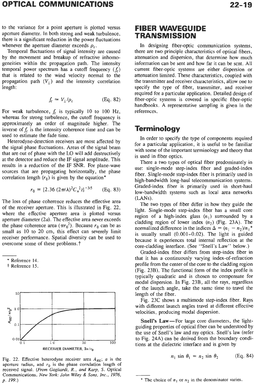
Because of aperture averaging, power fluctuations are
reduced in direct-detection receivers if the aperture area
is large compared to the intensity coherence area
(~p:).
This
is
illustrated in Fig. 21, where the ratio of
the signal-power variance for a receiver of diameter
2a
2Il/(XZ)’’~
Fig.
21.
Aperture averaging in direct-detection receivers
for
strong and weak turbulence. The received power variance is
normalized
to
the variance
for
a point aperture;
a
=
aperture
radius.
(From Fante,
R.
L.
“Electromagnetic Beam Propaga-
tion in Turbulent Media,”
Proc.
IEEE,
63,
December
1975,
p.
1680.)
22-19
to the variance for a point aperture is plotted versus
aperture diameter. In both strong and weak turbulence,
there is a significant reduction in the power fluctuations
whenever the aperture diameter exceeds
pc
.
Temporal fluctuations of signal intensity are caused
by the movement and breakup of refractive inhomo-
geneities within the propagation path. The intensity
temporal power spectrum has a cutoff frequency
(A)
that is related to the wind velocity normal to the
propagation path
(V,
)
and the intensity correlation
length:
f,
=
VllP,
For weak turbulence,
f,
is typically
10
to
100
Hz,
whereas for strong turbulence, the cutoff frequency is
approximately an order
of
magnitude higher. The
inverse off, is the intensity coherence time and can be
used to estimate the fade time.
Heterodyne-detection receivers
are
most affected by
the signal phase fluctuations. Areas of the signal beam
that are out
of
phase with the LO will add destructively
at the detector and reduce the IF signal amplitude. This
results in a reduction of the IF
SNR.
For plane-wave
sources that are propagating horizontally, the phase
correlation length
(ro)
is given by the equation*
ro
=
t2.36
(~T/A)~C,~Z]-~’~
(Eq. 83)
The loss of phase coherence reduces the effective area
of the receiver aperture. This is illustrated in Fig.
22,
where the effective aperture area is plotted versus
aperture diameter (24. The effective area never exceeds
the phase coherence area
(m:).
Because
ro
can be as
small as
10
to 20 cm, this effect can severely limit
receiver performance. Spatial diversity can be used to
overcome some of these problems.
t
*
Reference
14.
t
Reference
15.
RECEIVER DIAMETER.
20/r0
Fig.
22.
Effective heterodyne receiver area
ARE;
u is the
aperture radius, and
ro
is the phase correlation length
of
received signal.
(From Gugliurdi,
R.,
and
Kurp,
S.
Optical
Communications.
New
York: John
Wiley
&
Sons,
Inc., 1976,
p.
199.)
FIBER WAVEGUIDE
TRANSMISSION
In designing fiber-optic communication systems,
there are two principle characteristics of optical fibers,
attenuation and dispersion, that determine how much
information can be sent and how far it can be sent. All
current fiber-optic systems are either dispersion or
attenuation limited. These characteristics, coupled with
the transmitter and receiver characteristics, allow one to
specify the type of fiber, transmitter, and receiver
required for a particular application. Detailed design of
fiber-optic systems is covered in specific fiber-optic
handbooks. A representative sampling is given in the
references.
Terminology
In order to specify the type of components required
for a particular application, it is useful to be familiar
with some of the important terminology and theory that
is used in fiber optics.
There a two types of optical fiber predominately in
use: single-mode step-index fiber and graded-index
fiber. Single-mode step-index fiber is primarily used in
high-bandwidth long-haul telecommunication systems.
Graded-index fiber is primarily used in short-haul
low-bandwidth systems such as local area networks
(LANs).
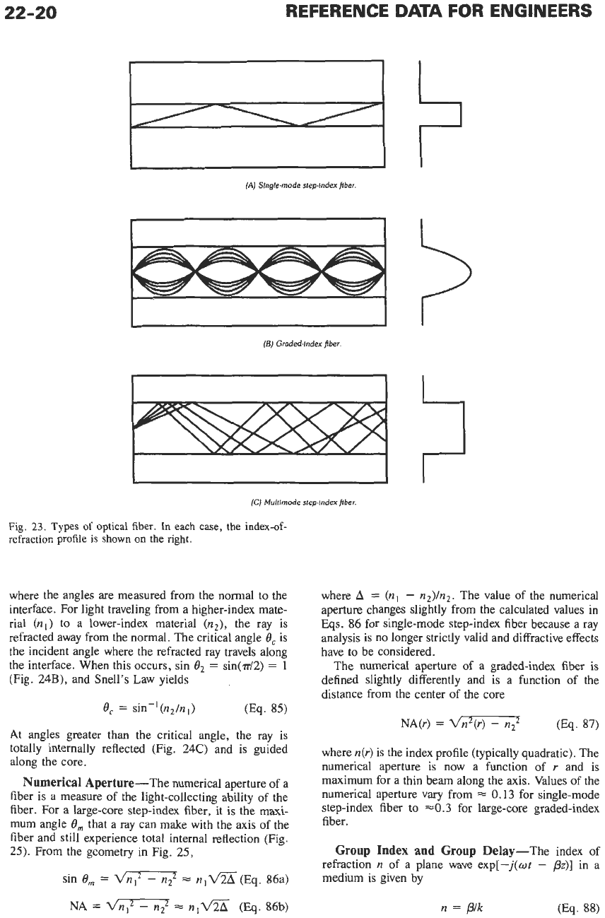
The two types of fiber differ in how they guide the
light. Single-mode step-index fiber has a small core
region of a high-index glass
(n,)
surrounded by a
cladding region of lower index
(n2)
(Fig. 23A). The
normalized difference in the indices
A
=
(nl
-
n2)/nl
*
is usually small (0.001-0.02). The light is guided
because it experiences total internal reflection at the
core-cladding interface. (See “Snell’s Law” below
.)
Graded-index fiber differs from step-index fiber in
that it has a continuously varying index-of-refraction
profile from the center of the core to the cladding region
(Fig. 23B). The functional form of the index profile is
typically quadratic and is chosen to compensate for
modal dispersion. In Fig. 23B, all the rays, regardless
of the launch angle, take the same time to travel the
length of the fiber.
Fig. 23C shows a multimode step-index fiber. Rays
with different launch angles travel at different effective
velocities, producing modal dispersion.
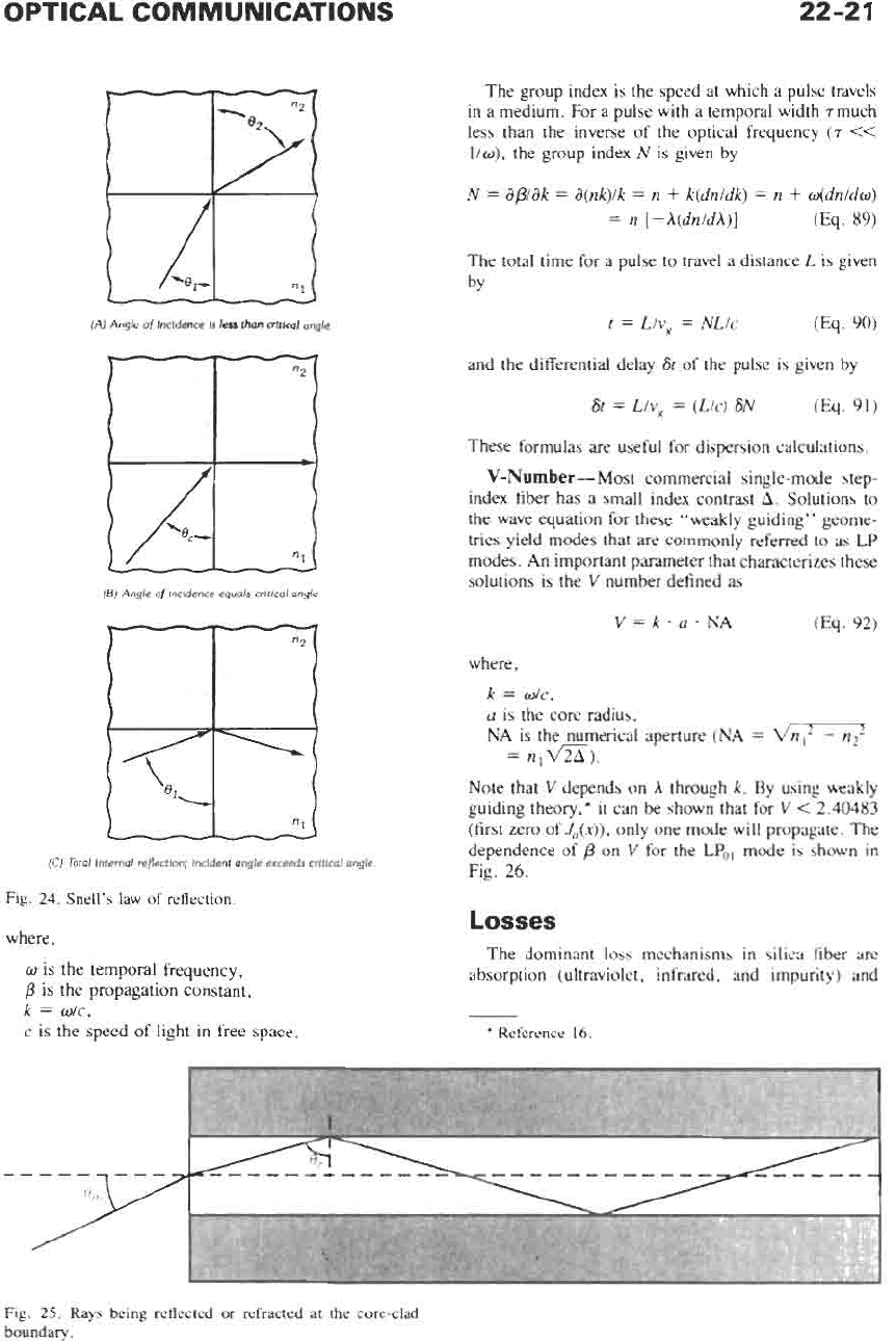
Snell’s
Law-For large core diameters, the light-
guiding properties of optical fiber can be understood by
the use
of
Snell’s law and ray optics. Snell’s law (refer
to Fig. 24A) can be derived from the boundary condi-
tions at the dielectric interface and is given by
nl
sin
=
n2
sin
02 (Eq.
84)
-
*
The choice
of
n,
or
n2
in the denominator varies.
22-20
REFERENCE
DATA
FOR ENGINEERS
CI
I
I
I
(AJ
Slnglc-mode steplndex pber
(5)
Graded-index fiber
I
I
I
(Cj
Multimode
step-index fiber.
Fig.
23.
Types
of
optical
fiber.
In
each
case,
the
index-of-
refraction
profile
is
shown
on
the
right.
where the angles are measured from the normal to the
interface. For light traveling from a higher-index mate-
rial
(nl)
to a lower-index material
(n2),
the ray is
refracted away from the normal. The critical angle
8,
is
the incident angle where the refracted ray travels along
the interface. When this occurs, sin
O2
=
sin(d2)
=
1
(Fig.
24B),
and Snell's Law yields
ec
=
sin-'(n,/n,)
(Eq.
85)
At angles greater than the critical angle, the ray is
totally internally reflected (Fig. 24C) and is guided
along the core.
Numerical Aperture-The numerical aperture of a
fiber is a measure
of
the light-collecting ability of the
fiber. For a large-core step-index fiber,
it
is
the maxi-
mum angle
8,
that a ray can make with the axis of the
fiber and still experience total internal reflection (Fig.
25).
From the geometry in Fig.
25,
sin
ern
=
dn12
-
nt
=
nlV%(Eq.
86a)
NA
=
dn12
-
n:
=
nlV%
(Eq.
86b)
where
A
=
(nl
-
n2)/n2. The value of the numerical
aperture changes slightly from the calculated values in
Eqs.
86
for single-mode step-index fiber because a ray
analysis
is
no longer strictly valid and diffractive effects
have to be considered.
The numerical aperture
of
a graded-index fiber is
defined slightly differently and is a function of the
distance from the center
of
the core
where n(r) is the index profile (typically quadratic). The
numerical aperture is now a function of
r
and is
maximum for a thin beam along the axis. Values
of
the
numerical aperture vary from
0.13
for single-mode
step-index fiber
to
~0.3
for large-core graded-index
fiber.
Group Index and Group Delay-The index of
refraction
n
of a plane wave exp[-j(ot
-
pz)]
in a
medium is given by
n
=
p/k
(E¶.
88)
OPTICAL COMMUNICATIONS
22-21
(A)
Angk
of
lncldmce
Is
lar
than
altknl
angk.
I
(6)
Angk
of
Incldmce
wah
ciitlml
angle.
7
(C)
Total
lnvmal
reflcalm;
lncldmt
angle
exceeds
c~ItIrnI
angle.
Fig.
24.
Snell’s
law
of reflection.
where,
w
is the temporal frequency,
/3
is the propagation constant,
k
=
dc,
c
is the
speed
of light in
free
space.
The group index is the
speed
at which a pulse travels
in a medium. For a pulse with a temporal width
T
much
less
than the inverse
of
the optical frequency
(T
CC
llw),
the group index
N
is
given by
N
=
apak
=
a(nk)lk
=
n
+
k(dn1dk)
=
n
+
ddnldo)
=
n
[-A(dnldA)]
(Eq.
89)
The total time
for
a pulse to travel a distance
L
is given
bY
t
=
Llv8
=
NL/c
(Eq.
90)
and the differential delay
St
of the pulse is given by
St
=
LlV8
=
(LIC)
SN
These formulas
are
useful for dispersion calculations.
V-Number-Most commercial single-mode step-
index fiber has a small index contrast
A.
Solutions to
the
wave
equation
for
these “weakly guiding” geome-
tries
yield modes that
are
commonly referred to as
LP
modes. An important parameter that characterizes these
solutions is the
V
number defined as
(Es.
91)
where,
k
=
dc,
a
is the core radius,
NA
is the numerical aperture
(NA
=
=
n,VZi).
Note that
V
depends on
A
through
k.
By using weakly
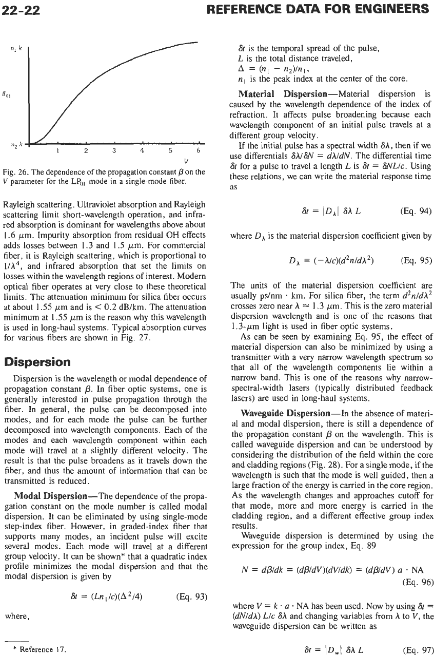
guiding theory,* it can be shown that for
V
<
2.40483
(first
zero
of
JJx)),
only one mode will propagate. The
dependence
of
/3
on
V
for the
LPo,
mode is shown in
Fig.
26.
Losses
The dominant loss mechanisms in silica fiber
are
absorption (ultraviolet, infrared, and impurity) and
*
Reference
16.
Fig. 25.
Rays
being reflected
or
refracted at
the
core-clad
boundary.
V
Fig.
26.
The dependence
of
the propagation constant
p
on
the
V
parameter
for
the
LPo,
mode
in
a
single-mode fiber.
Rayleigh scattering. Ultraviolet absorption and Rayleigh
scattering limit short-wavelength operation, and infra-
red absorption is dominant for wavelengths above about
1.6
ym. Impurity absorption from residual
OH
effects
adds losses between 1.3 and
1.5
pm. For commercial
fiber, it is Rayleigh scattering, which
is
proportional to
UA4,
and infrared absorption that set the limits on
losses within the wavelength regions of interest. Modern
optical fiber operates at very close to these theoretical
limits. The attenuation minimum for silica fiber occurs
at about
1.55
pm and is
<
0.2
dB/km. The attenuation
minimum at
1.55
pm is the reason why this wavelength
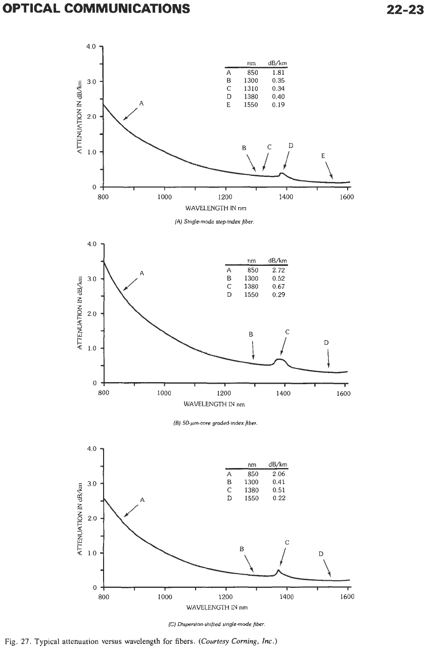
is used in long-haul systems. Typical absorption curves
for various fibers are shown in Fig.
27.
Dispersion
Dispersion is the wavelength
or
modal dependence of
propagation constant
p.
In fiber optic systems, one is
generally interested in pulse propagation through the
fiber. In general, the pulse can be decomposed into
modes, and for each mode the pulse can be further
decomposed into wavelength components. Each of the
modes and each wavelength component within each
mode will travel at a slightly different velocity. The
result is that the pulse broadens as it travels down the
fiber, and thus the amount of information that can be
transmitted is reduced.
Modal Dispersion-The dependence of the propa-
gation constant on the mode number is called modal
dispersion. It can be eliminated by using single-mode
step-index fiber. However, in graded-index fiber that
supports many modes, an incident pulse will excite
several modes. Each mode will travel at a different
group velocity. It can be shown* that a quadratic index
profile minimizes the modal dispersion and that the
modal dispersion is given by
St
=
(Ln
I
/c)(A
2/4)
(Eq.
93)
where,
St
is the temporal spread of the pulse,
L is the total distance traveled,
nl
is the peak index at the center of the core.
Material Dispersion-Material dispersion is
caused by the wavelength dependence of the index of
refraction. It affects pulse broadening because each
wavelength component of an initial pulse travels at a
different group velocity.
If
the initial pulse has a spectral width
6A,
then if we
use differentials
SIISN
=
dh/dN.
The differential time
St
for a pulse to travel a length
L
is
St
=
GNL/c.
Using
these relations, we can write the material response time
as
A
=
(nl
-
n2)/nl,
where
DA
is the material dispersion coefficient given by
DA
=
(-A/c)(d2n/dA2)
(Eq.
95)
The units
of
the material dispersion coefficient are
usually pdnm
km. For silica fiber, the term
d2n/dA2
crosses zero near
h
=
1.3 pm. This is the zero material
dispersion wavelength and is one
of
the reasons that
1.3-ym light is used in fiber optic systems.
As
can be seen by examining Eq.
95,
the effect
of
material dispersion can
also
be minimized by using a
transmitter with a very narrow wavelength spectrum
so
that all of the wavelength components lie within a
narrow band. This
is
one of the reasons why narrow-
spectral-width lasers (typically distributed feedback
lasers) are used in long-haul systems.
Waveguide Dispersion-In the absence of materi-
al and modal dispersion, there is still a dependence of
the propagation constant
/3
on the wavelength. This is
called waveguide dispersion and can be understood by
considering the distribution of the field within the core
and cladding regions (Fig.
28).
For a single mode, if the
wavelength is such that the mode is well guided, then a
large fraction of the energy is carried in the core region.
As
the wavelength changes and approaches cutoff for
that mode, more and more energy is carried in the
cladding region, and a different effective group index
results.
Waveguide dispersion is determined by using the
expression for the group index, Eq.
89
N
=
dp/dk
=
(dp/dV)(dV/dk)
=
(dp/dV)
a
.
NA
(Eq.
96)
where
V
=
k
.
a
*
NA has been used. Now by using 6t
=
(dN/dA)
L/c
SA and changing variables from
A
to
V,
the
waveguide dispersion can be written as
*
Reference 17.
6t
=
ID,\
SAL
(Eq.
97)
OPTICAL COMMUNICATIONS
22-23
$
4'0
3.0
1
z
z
0
2.0
F:
a
3
6
5
1.0
nm
dB/km
A
850 1.81
B
1300 0.35
C
1310 0.34
D
1380 0.40
E
1550 0.19
/A
P
\
-\
J
J
E\
I
0
800 1000 1200
1400
1600
WAVELENGTH
IN
nm
(A)
Slngle-mode step-Index fiber.
z
2
2
2.0
4
P
Q
1.0
h
/A
I'
nm
dBh
A
850 2.72
B
1300 0.52
C
1380 0.67
D
1550 0.29
D
C
o!
I
I
I I I
I
I
800
1000
1200 1400 1600
WAVELENGTH
IN
nm
(5)
50.sm-core graded-Index fiber
4.0
nm dBhm
A
850 2.06
B
1300 0.41
C
1380 0.51
D
1550 0.22
-I
800
1000
1200 1400 1600
WAVELENGTH
IN
nm
(C)
Dlsperslon-shifted single-mode fiber.
Fig.
27.
Typical attenuation versus wavelength
for
fibers.
(Courtesy Corning,
hc.)