Munson B.R. Fundamentals of Fluid Mechanics
Подождите немного. Документ загружается.

8.1 General Characteristics of Pipe Flow 387
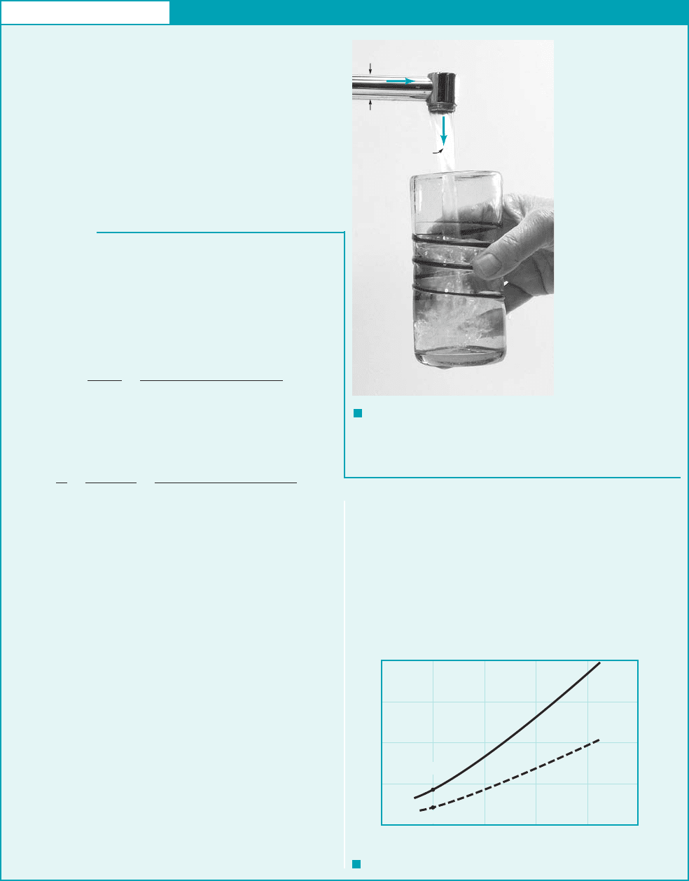
GIVEN Water at a temperature of 50 °F flows through a pipe
of diameter D 0.73 in. and into a glass as shown in Fig. E8.1a.
FIND Determine
(a) the minimum time taken to fill a 12-oz glass (volume
0.0125 ft
3
) with water if the flow in the pipe is to be laminar.
Repeat the calculations if the water temperature is 140 °F.
(b) the maximum time taken to fill the glass if the flow is to be tur-
bulent. Repeat the calculations if the water temperature is 140 °F.
S
OLUTION
F I G U R E E8.1
a
F I G U R E E8.1
b
Laminar or Turbulent Flow
E
XAMPLE 8.1
(a) If the flow in the pipe is to remain laminar, the minimum
time to fill the glass will occur if the Reynolds number is the max-
imum allowed for laminar flow, typically
Thus, where from Table B.1,
and at while
and at Thus, the maximum
average velocity for laminar flow in the pipe is
Similarly, at With of glass
and we obtain
(Ans)
Similarly, at To maintain laminar flow, the less
viscous hot water requires a lower flowrate than the cold water.
(b) If the flow in the pipe is to be turbulent, the maximum time to
fill the glass will occur if the Reynolds number is the minimum al-
lowed for turbulent flow, Thus,
and
at
(Ans)
Similarly, and at
COMMENTS Note that because water is “not very viscous,”
the velocity must be “fairly small” to maintain laminar flow. In
general, turbulent flows are encountered more often than lami-
nar flows because of the relatively small viscosity of most com-
mon fluids (water, gasoline, air). By repeating the calculations
at various water temperatures, T (i.e., with different densities
and viscosities), the results shown in Fig. E8.1b are obtained. As
the water temperature increases, the kinematic viscosity,
/, decreases and the corresponding times to fill the glass
increase as indicated. (Temperature effects on the viscosity of
gases are the opposite; increase in temperature causes an in-
crease in viscosity.)
140 °F.t 12.8 sV 0.335 ft
s
50 °Ft 4.65 s
rD 0.925 ft
s
V 4000m
Re 4000.
140 °F.t 24.4 s
8.85 s at T 50 °F
t
V
Q
V
1p
42D
2
V
410.0125 ft
3
2
1p 30.73
124
2
ft
2
210.486 ft
s2
VQt
Vvolume140 °F.V 0.176 ft
s
0.486 lb
#
s
slug 0.486 ft
s
V
2100m
rD
210012.73 10
5
lb
#
s
ft
2
2
11.94 slugs
ft
3
210.73
12 ft2
140 °F.lb
#
s
ft
2
m 0.974 10
5
r 1.91 slugs
ft
3
50 °F,m 2.73 10
5
lb
#
s
ft
2
slugs
ft
3
r 1.94V 2100 m
rD,
Re rVD
m 2100.
If the flowing fluid had been honey with a kinematic viscosity
( /) 3000 times greater than that of water, the velocities given
earlier would be increased by a factor of 3000 and the times re-
duced by the same factor. As shown in the following sections, the
pressure needed to force a very viscous fluid through a pipe at such
a high velocity may be unreasonably large.
,
Q
D
V
laminar
flow
turbulent
flow
40
30
20
10
0
0 50 100 150 200 250
(50
°
F, 8.85 s)
(50
°
F, 4.65 s)
T,
°
F
t, s
JWCL068_ch08_383-460.qxd 9/23/08 10:50 AM Page 387
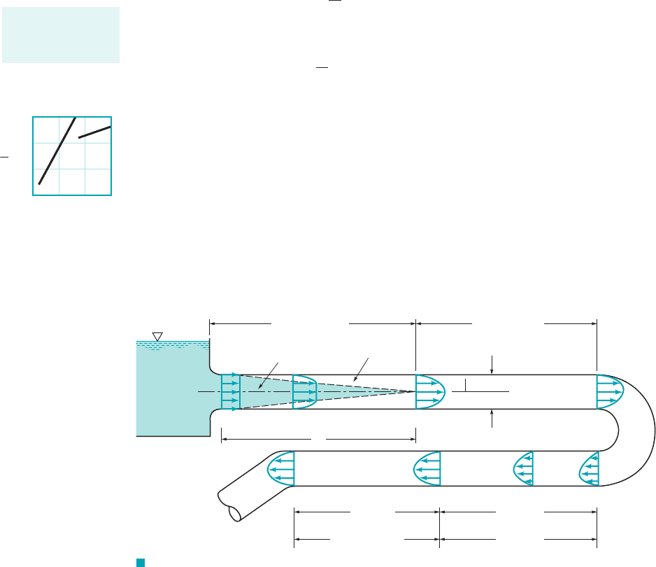
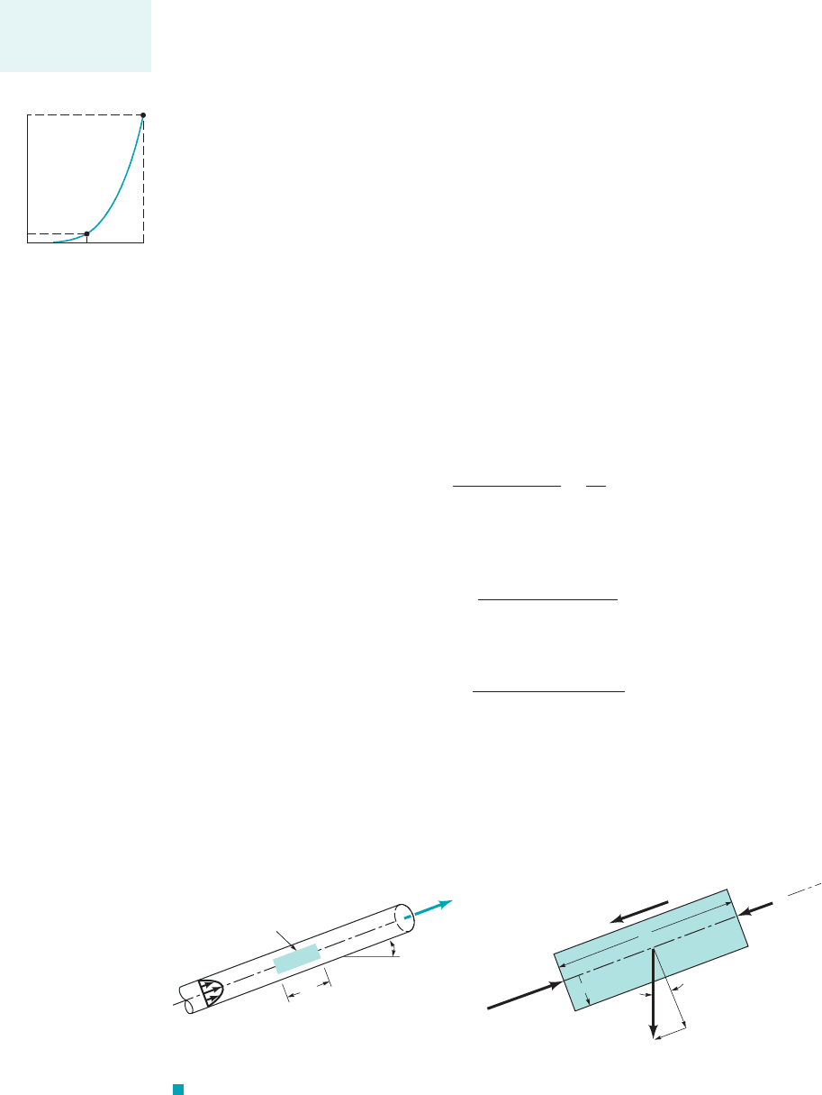
8.1.2 Entrance Region and Fully Developed Flow
Any fluid flowing in a pipe had to enter the pipe at some location. The region of flow near where
the fluid enters the pipe is termed the entrance region and is illustrated in Fig. 8.5. It may be the
first few feet of a pipe connected to a tank or the initial portion of a long run of a hot air duct com-
ing from a furnace.
As is shown in Fig. 8.5, the fluid typically enters the pipe with a nearly uniform velocity
profile at section 112. As the fluid moves through the pipe, viscous effects cause it to stick to the
pipe wall 1the no-slip boundary condition2. This is true whether the fluid is relatively inviscid air
or a very viscous oil. Thus, a boundary layer in which viscous effects are important is produced
along the pipe wall such that the initial velocity profile changes with distance along the pipe, x,
until the fluid reaches the end of the entrance length, section 122, beyond which the velocity pro-
file does not vary with x. The boundary layer has grown in thickness to completely fill the pipe.
Viscous effects are of considerable importance within the boundary layer. For fluid outside the
boundary layer [within the inviscid core surrounding the centerline from 112to 122], viscous effects
are negligible.
The shape of the velocity profile in the pipe depends on whether the flow is laminar or tur-
bulent, as does the length of the entrance region, As with many other properties of pipe flow,
the dimensionless entrance length, correlates quite well with the Reynolds number. Typi-
cal entrance lengths are given by
(8.1)
and
(8.2)
For very low Reynolds number flows the entrance length can be quite short if
whereas for large Reynolds number flows it may take a length equal to many pipe diameters before
the end of the entrance region is reached for For many practical engineer-
ing problems, so that as shown by the figure in the margin,
Calculation of the velocity profile and pressure distribution within the entrance region is
quite complex. However, once the fluid reaches the end of the entrance region, section 122of Fig.
8.5, the flow is simpler to describe because the velocity is a function of only the distance from
the pipe centerline, r, and independent of x. This is true until the character of the pipe changes
in some way, such as a change in diameter, or the fluid flows through a bend, valve, or some
other component at section 132. The flow between 122and 132is termed fully developed flow. Be-
yond the interruption of the fully developed flow [at section 142], the flow gradually begins its
20D 6/
e
6 30D.10
4
6 Re 6 10
5
Re ⫽ 20002.1/
e
⫽ 120D
Re ⫽ 102,1/
e
⫽ 0.6D
/
e
D
⫽ 4.4 1Re2
1
Ⲑ
6
for turbulent flow
/
e
D
⫽ 0.06 Re for laminar flow
/
e
Ⲑ
D,
/
e
.
388 Chapter 8 ■ Viscous Flow in Pipes
Inviscid core
Boundary layer
Entrance region
flow
Fully developed
flow
D
x
r
(2)(1)
ᐉ
e
(3)
(4)(5)(6)
x
6
– x
5
Fully developed
flow
x
5
– x
4
Developing
flow
F I G U R E 8.5 Entrance region, developing flow, and fully developed flow in a pipe
system.
The entrance length
is a function of the
Reynolds number.
100
10
1
0.1
10
6
10
4
10
2
10
0
ᐉ
e
D
Re
JWCL068_ch08_383-460.qxd 9/23/08 10:50 AM Page 388
return to its fully developed character [section 152] and continues with this profile until the next
pipe system component is reached [section 162]. In many cases the pipe is long enough so that
there is a considerable length of fully developed flow compared with the developing flow length
and
In other cases the distances between one component
1bend, tee, valve, etc.2of the pipe system and the next component is so short that fully developed
flow is never achieved.
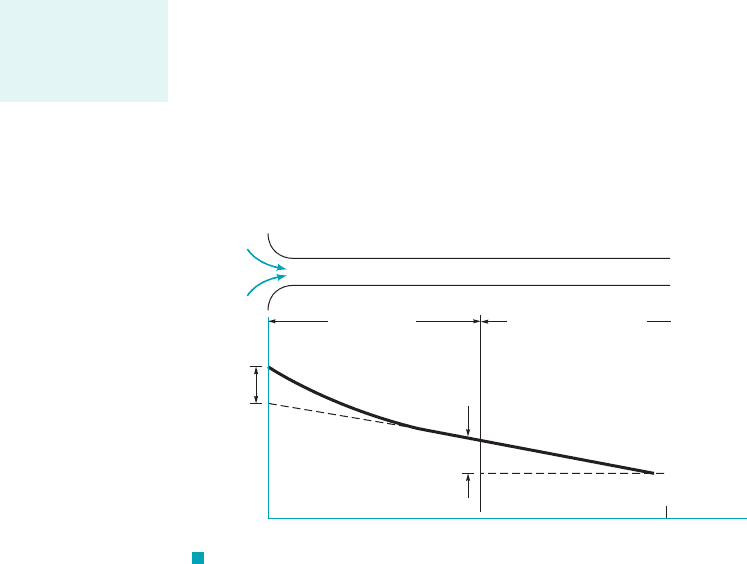
8.1.3 Pressure and Shear Stress
Fully developed steady flow in a constant diameter pipe may be driven by gravity and兾or pressure
forces. For horizontal pipe flow, gravity has no effect except for a hydrostatic pressure variation
across the pipe, that is usually negligible. It is the pressure difference, between
one section of the horizontal pipe and another which forces the fluid through the pipe. Viscous ef-
fects provide the restraining force that exactly balances the pressure force, thereby allowing the
fluid to flow through the pipe with no acceleration. If viscous effects were absent in such flows,
the pressure would be constant throughout the pipe, except for the hydrostatic variation.
In non-fully developed flow regions, such as the entrance region of a pipe, the fluid accel-
erates or decelerates as it flows 1the velocity profile changes from a uniform profile at the entrance
of the pipe to its fully developed profile at the end of the entrance region2. Thus, in the entrance
region there is a balance between pressure, viscous, and inertia 1acceleration2forces. The result is
a pressure distribution along the horizontal pipe as shown in Fig. 8.6. The magnitude of the pres-
sure gradient, is larger in the entrance region than in the fully developed region, where it
is a constant,
The fact that there is a nonzero pressure gradient along the horizontal pipe is a result of vis-
cous effects. As is discussed in Chapter 3, if the viscosity were zero, the pressure would not vary
with x. The need for the pressure drop can be viewed from two different standpoints. In terms of
a force balance, the pressure force is needed to overcome the viscous forces generated. In terms
of an energy balance, the work done by the pressure force is needed to overcome the viscous dis-
sipation of energy throughout the fluid. If the pipe is not horizontal, the pressure gradient along it
is due in part to the component of weight in that direction. As is discussed in Section 8.2.1, this
contribution due to the weight either enhances or retards the flow, depending on whether the flow
is downhill or uphill.
The nature of the pipe flow is strongly dependent on whether the flow is laminar or turbu-
lent. This is a direct consequence of the differences in the nature of the shear stress in laminar and
turbulent flows. As is discussed in some detail in Section 8.3.3, the shear stress in laminar flow is
a direct result of momentum transfer among the randomly moving molecules 1a microscopic phe-
nomenon2. The shear stress in turbulent flow is largely a result of momentum transfer among the
randomly moving, finite-sized fluid particles 1a macroscopic phenomenon2. The net result is that
the physical properties of the shear stress are quite different for laminar flow than for turbulent
flow.
0p
0x ¢p
/60.
0p
0x,
¢p p
1
p
2
,gD,
1x
6
x
5
2 1x
5
x
4
24.31x
3
x
2
2 /
e
8.1 General Characteristics of Pipe Flow 389
Entrance
pressure
drop
Entrance flow
Fully developed
flow:
p/ x = constant
∂∂
Δp
x
3
– x
2
= ᐉ
x
2
= ᐉ
e
x
1
= 0
p
x
3
x
F I G U R E 8.6 Pressure distribution along a horizontal pipe.
Laminar flow char-
acteristics are dif-
ferent than those
for turbulent flow.
JWCL068_ch08_383-460.qxd 9/23/08 10:50 AM Page 389

390 Chapter 8 ■ Viscous Flow in Pipes
As is indicated in the previous section, the flow in long, straight, constant diameter sections of a
pipe becomes fully developed. That is, the velocity profile is the same at any cross section of the
pipe. Although this is true whether the flow is laminar or turbulent, the details of the velocity pro-
file 1and other flow properties2are quite different for these two types of flow. As will be seen in
the remainder of this chapter, knowledge of the velocity profile can lead directly to other useful
information such as pressure drop, head loss, flowrate, and the like. Thus, we begin by develop-
ing the equation for the velocity profile in fully developed laminar flow. If the flow is not fully de-
veloped, a theoretical analysis becomes much more complex and is outside the scope of this text.
If the flow is turbulent, a rigorous theoretical analysis is as yet not possible.
Although most flows are turbulent rather than laminar, and many pipes are not long enough
to allow the attainment of fully developed flow, a theoretical treatment and full understanding of
fully developed laminar flow is of considerable importance. First, it represents one of the few the-
oretical viscous analyses that can be carried out “exactly” 1within the framework of quite general
assumptions2without using other ad hoc assumptions or approximations. An understanding of the
method of analysis and the results obtained provides a foundation from which to carry out more
complicated analyses. Second, there are many practical situations involving the use of fully devel-
oped laminar pipe flow.
There are numerous ways to derive important results pertaining to fully developed laminar
flow. Three alternatives include: 112from applied directly to a fluid element, 122from the
Navier–Stokes equations of motion, and 132from dimensional analysis methods.
8.2.1 From Applied Directly to a Fluid Element
We consider the fluid element at time t as is shown in Fig. 8.7. It is a circular cylinder of fluid of
length and radius r centered on the axis of a horizontal pipe of diameter D. Because the veloc-
ity is not uniform across the pipe, the initially flat ends of the cylinder of fluid at time t become
distorted at time when the fluid element has moved to its new location along the pipe as
shown in the figure. If the flow is fully developed and steady, the distortion on each end of the
fluid element is the same, and no part of the fluid experiences any acceleration as it flows, as shown
by the figure in the margin. The local acceleration is zero because the flow is steady,
and the convective acceleration is zero because the flow is fully devel-
oped. Thus, every part of the fluid merely flows along its streamline parallel to the pipe walls with
constant velocity, although neighboring particles have slightly different velocities. The velocity
varies from one pathline to the next. This velocity variation, combined with the fluid viscosity, pro-
duces the shear stress.
If gravitational effects are neglected, the pressure is constant across any vertical cross sec-
tion of the pipe, although it varies along the pipe from one section to the next. Thus, if the pres-
sure is at section 112, it is at section 122where is the pressure drop be-
tween sections (1) and (2). We anticipate the fact that the pressure decreases in the direction of
flow so that A shear stress, acts on the surface of the cylinder of fluid. This viscous
stress is a function of the radius of the cylinder,
As was done in fluid statics analysis 1Chapter 22, we isolate the cylinder of fluid as is shown
in Fig. 8.8 and apply Newton’s second law, In this case, even though the fluid is mov-
ing, it is not accelerating, so that Thus, fully developed horizontal pipe flow is merely aa
x
⫽ 0.
F
x
⫽ ma
x
.
t ⫽ t1r2.
t,¢p 7 0.
¢pp
2
⫽ p
1
⫺ ¢pp ⫽ p
1
1V ⴢ V ⫽ u 0u
Ⲑ
0x i
ˆ
⫽ 02
10V
Ⲑ
0t ⫽ 02
t ⫹ dt
/
F ⴝ ma
F ⫽ ma
8.2 Fully Developed Laminar Flow
Steady, fully devel-
oped pipe flow ex-
periences no
acceleration.
Velocity profiles
Streamlines
(1) (2)
D
Velocity
profile
V = u(r)i
r
Fluid element at time t
Element at time t + t
δ
x
ᐉ
^
F I G U R E 8.7 Motion
of a cylindrical fluid element within a
pipe.
JWCL068_ch08_383-460.qxd 9/23/08 10:50 AM Page 390
balance between pressure and viscous forces—the pressure difference acting on the end of the
cylinder of area and the shear stress acting on the lateral surface of the cylinder of area
This force balance can be written as
which can be simplified to give
(8.3)
Equation 8.3 represents the basic balance in forces needed to drive each fluid particle along
the pipe with constant velocity. Since neither are functions of the radial coordinate, r, it
follows that must also be independent of r. That is, where C is a constant. At
1the centerline of the pipe2there is no shear stress At 1the pipe wall2the shear
stress is a maximum, denoted the wall shear stress. Hence, and the shear stress
distribution throughout the pipe is a linear function of the radial coordinate
(8.4)
as is indicated in Fig. 8.9. The linear dependence of on r is a result of the pressure force being
proportional to 1the pressure acts on the end of the fluid cylinder; 2and the shear
force being proportional to r 1the shear stress acts on the lateral sides of the cylinder; area 2.
If the viscosity were zero there would be no shear stress, and the pressure would be constant
throughout the horizontal pipe As is seen from Eqs. 8.3 and 8.4, the pressure drop and
wall shear stress are related by
(8.5)
A small shear stress can produce a large pressure difference if the pipe is relatively long
Although we are discussing laminar flow, a closer consideration of the assumptions involved
in the derivation of Eqs. 8.3, 8.4, and 8.5 reveals that these equations are valid for both laminar
and turbulent flow. To carry the analysis further we must prescribe how the shear stress is related
to the velocity. This is the critical step that separates the analysis of laminar from that of turbulent
flow—from being able to solve for the laminar flow properties and not being able to solve for the
turbulent flow properties without additional ad hoc assumptions. As is discussed in Section 8.3,
the shear stress dependence for turbulent flow is very complex. However, for laminar flow of a
1/
D 12.
¢p
4/t
w
D
1¢p 02.
2pr/
area pr
2
r
2
t
t
2t
w
r
D
C 2t
w
Dt
w
,
r D
21t 02.
r 0t Cr,2t
r
¢p nor /
¢p
/
2t
r
1p
1
2pr
2
1p
1
¢p2pr
2
1t22pr/ 0
2pr/.pr
2
,
8.2 Fully Developed Laminar Flow 391
2 rᐉ
τπ
(p
1
– Δp) r
2
π
x
r
ᐉ
p
1
r
2
π
F I G U R E 8.8 Free-body
diagram of a cylinder of fluid.
τ
V
c
(r)
τ
r
(0) = 0
τ
(D/2) =
w
ττ
Laminar
profile
u(r)
Ideal
(inviscid)
profile
x
V = V
c
/2
w
F I G U R E 8.9
Shear stress distribution within the
fluid in a pipe (laminar or turbulent
flow) and typical velocity profiles.
Basic horizontal
pipe flow is gov-
erned by a balance
between viscous
and pressure
forces.
JWCL068_ch08_383-460.qxd 9/23/08 10:50 AM Page 391
Newtonian fluid, the shear stress is simply proportional to the velocity gradient,
1see Section 1.62. In the notation associated with our pipe flow, this becomes
(8.6)
The negative sign is included to give with 1the velocity decreases from the pipe
centerline to the pipe wall2.
Equations 8.3 and 8.6 represent the two governing laws for fully developed laminar flow of
a Newtonian fluid within a horizontal pipe. The one is Newton’s second law of motion and the
other is the definition of a Newtonian fluid. By combining these two equations we obtain
which can be integrated to give the velocity profile as follows:
or
where is a constant. Because the fluid is viscous it sticks to the pipe wall so that at
Thus, Hence, the velocity profile can be written as
(8.7)
where is the centerline velocity. An alternative expression can be written by us-
ing the relationship between the wall shear stress and the pressure gradient 1Eqs. 8.5 and 8.72to give
where is the pipe radius.
This velocity profile, plotted in Fig. 8.9, is parabolic in the radial coordinate, r, has a max-
imum velocity, at the pipe centerline, and a minimum velocity 1zero2at the pipe wall. The vol-
ume flowrate through the pipe can be obtained by integrating the velocity profile across the pipe.
Since the flow is axisymmetric about the centerline, the velocity is constant on small area elements
consisting of rings of radius r and thickness dr as shown in the figure in the margin. Thus,
or
By definition, the average velocity is the flowrate divided by the cross-sectional area,
so that for this flow
(8.8)
and
(8.9)Q ⫽
pD
4
¢p
128m/
V ⫽
pR
2
V
c
2pR
2
⫽
V
c
2
⫽
¢pD
2
32m/
V ⫽ Q
Ⲑ
A ⫽ Q
Ⲑ
pR
2
,
Q ⫽
pR
2
V
c
2
Q ⫽
冮
u dA ⫽
冮
r⫽R
r⫽0
u1r22pr dr ⫽ 2p V
c
冮
R
0
c1 ⫺ a
r
R
b
2
dr dr
V
c
,
R ⫽ D
Ⲑ
2
u1r2⫽
t
w
D
4m
c1 ⫺ a
r
R
b
2
d
V
c
⫽ ¢pD
2
Ⲑ
116m/2
u1r2⫽ a
¢pD
2
16m/
bc1 ⫺ a
2r
D
b
2
d⫽ V
c
c1 ⫺ a
2r
D
b
2
d
C
1
⫽ 1¢p
Ⲑ
16m/2D
2
.r ⫽ D
Ⲑ
2.
u ⫽ 0C
1
u ⫽⫺a
¢p
4m/
b r
2
⫹ C
1
冮
du ⫽⫺
¢p
2m/
冮
r dr
du
dr
⫽⫺a
¢p
2m/
b r
du
Ⲑ
dr 6 0t 7 0
t ⫽⫺m
du
dr
“t ⫽ m du
Ⲑ
dy”
392 Chapter 8 ■ Viscous Flow in Pipes
Under certain re-
strictions the veloc-
ity profile in a pipe
is parabolic.
R
dr
r
dA
= 2 r dr
π
JWCL068_ch08_383-460.qxd 9/23/08 10:50 AM Page 392
As is indicated in Eq. 8.8, the average velocity is one-half of the maximum velocity. In general,
for velocity profiles of other shapes 1such as for turbulent pipe flow2, the average velocity is not
merely the average of the maximum and minimum 102velocities as it is for the laminar para-
bolic profile. The two velocity profiles indicated in Fig. 8.9 provide the same flowrate—one is the
fictitious ideal profile; the other is the actual laminar flow profile.
The above results confirm the following properties of laminar pipe flow. For a horizontal
pipe the flowrate is 1a2directly proportional to the pressure drop, 1b2inversely proportional to the
viscosity, 1c2inversely proportional to the pipe length, and 1d2proportional to the pipe diameter to
the fourth power. With all other parameters fixed, an increase in diameter by a factor of 2 will in-
crease the flowrate by a factor of 2
4
⫽ 16—the flowrate is very strongly dependent on pipe size.
This dependence is shown by the figure in the margin. Likewise, a small error in pipe diameter
can cause a relatively large error in flowrate. For example, a 2% error in diameter gives an 8% er-
ror in flowrate or so that This flow, the properties of
which were first established experimentally by two independent workers, G. Hagen 11797–18842
in 1839 and J. Poiseuille 11799–18692in 1840, is termed Hagen–Poiseuille flow. Equation 8.9 is
commonly referred to as Poiseuille’s law. Recall that all of these results are restricted to laminar
flow 1those with Reynolds numbers less than approximately 21002in a horizontal pipe.
The adjustment necessary to account for nonhorizontal pipes, as shown in Fig. 8.10, can be
easily included by replacing the pressure drop, by the combined effect of pressure and grav-
ity, , where is the angle between the pipe and the horizontal. 1Note that if
the flow is uphill, while if the flow is downhill.2This can be seen from the force balance
in the x direction 1along the pipe axis2on the cylinder of fluid shown in Fig. 8.10b. The method is
exactly analogous to that used to obtain the Bernoulli equation 1Eq. 3.62when the streamline is not
horizontal. The net force in the x direction is a combination of the pressure force in that direction,
and the component of weight in that direction, The result is a slightly mod-
ified form of Eq. 8.3 given by
(8.10)
Thus, all of the results for the horizontal pipe are valid provided the pressure gradient is adjusted
for the elevation term, that is, is replaced by so that
(8.11)
and
(8.12)
It is seen that the driving force for pipe flow can be either a pressure drop in the flow direction,
or the component of weight in the flow direction, If the flow is downhill, gravity
helps the flow 1a smaller pressure drop is required; 2. If the flow is uphill, gravity works
against the flow 1a larger pressure drop is required; 2. Note that 1whereg/ sin u ⫽ g¢zsin u 7 0
sin u 6 0
⫺g/ sin u.¢p,
Q ⫽
p1¢p ⫺ g/ sin u2D
4
128m/
V ⫽
1¢p ⫺ g/ sin u2D
2
32m/
¢p ⫺ g/ sin u¢p
¢p ⫺ g/ sin u
/
⫽
2t
r
⫺gpr
2
/ sin u.¢ppr
2
,
u 6 0
u 7 0u¢p ⫺ g/ sin u
¢p,
dQ
Ⲑ
Q ⫽ 4 dD
Ⲑ
D2.dQ ⬃ 4D
3
dD,1Q ⬃ D
4
1m ⫽ 02
1V
c
2
8.2 Fully Developed Laminar Flow 393
Poiseuille’s law is
valid for laminar
flow only.
sin = r
2
sin
θθγπ
π
p r
2
x
θ
r
2 r
τ
(b)(a)
Fluid cylinder
θ
Q
(p + Δp) r
2
π
π
F I G U R E 8.10 Free-body diagram of a fluid cylinder for flow in a nonhorizontal pipe.
~ D
4
Q
Q
D
D
0
Q
0
16Q
0
2D
0
JWCL068_ch08_383-460.qxd 9/23/08 10:50 AM Page 393

is the change in elevation2is a hydrostatic type pressure term. If there is no flow,
as expected for fluid statics.V 0 and ¢p g/ sin u g¢z,
¢z
394 Chapter 8 ■ Viscous Flow in Pipes
GIVEN An oil with a viscosity of and den-
sity flows in a pipe of diameter
FIND (a) What pressure drop, is needed to produce
a flowrate of if the pipe is horizontal with
and x
2
10 m?x
1
0
Q 2.0 10
5
m
3
s
p
1
p
2
,
D 0.020 m.r 900 kg
m
3
m 0.40 N
#
s
m
2
(b) How steep a hill, must the pipe be on if the oil is to flow
through the pipe at the same rate as in part 1a2, but with
(c) For the conditions of part 1b2, if what is the
pressure at section where x is measured along the pipe?x
3
5 m,
p
1
200 kPa,
p
1
p
2
?
u,
S
OLUTION
Laminar Pipe Flow
which is equivalent to that needed for
the horizontal pipe. For the horizontal pipe it is the work done by
the pressure forces that overcomes the viscous dissipation. For the
zero-pressure-drop pipe on the hill, it is the change in potential
energy of the fluid “falling” down the hill that is converted to the
energy lost by viscous dissipation. Note that if it is desired to in-
crease the flowrate to with the
value of given by Eq. 1 is Since the sine of an
angle cannot be greater than 1, this flow would not be possible.
The weight of the fluid would not be large enough to offset the
viscous force generated for the flowrate desired. A larger diame-
ter pipe would be needed.
(c) With the length of the pipe, does not appear in the
flowrate equation 1Eq. 12. This is a statement of the fact that for such
cases the pressure is constant all along the pipe 1provided the pipe
lies on a hill of constant slope2. This can be seen by substituting the
values of Qand from case 1b2into Eq. 8.12 and noting that
for any For example, if
Thus, so that
(Ans)
COMMENT Note that if the fluid were gasoline
and the Reynolds number would
be the flow would probably not be laminar, and
use of Eqs. 8.9 and 8.12 would give incorrect results. Also note
from Eq. 1 that the kinematic viscosity, is the impor-
tant viscous parameter. This is a statement of the fact that with
constant pressure along the pipe, it is the ratio of the viscous
force to the weight force that determines the
value of u.
1⬃g rg21⬃m2
n m
r,
Re 2790,
m
3
2,
r 680 kg
10
4
N
#
s
m
2
1m 3.1
p
3
200 kPa
p
1
p
2
p
3
/ x
3
x
1
5 m.¢p p
1
p
3
0/.
¢p 0u
/,p
1
p
2
sin u 1.15.u
p
1
p
2
,Q 1.0 10
4
m
3
s
N
m
2
,20,40012.31 m2
E
XAMPLE 8.2
(a) If the Reynolds number is less than 2100 the flow is
laminar and the equations derived in this section are valid. Since
the average velocity is
the Reynolds number is
Hence, the flow is laminar and from Eq.
8.9 with the pressure drop is
or
(Ans)
(b) If the pipe is on a hill of angle such that 0,
Eq. 8.12 gives
(1)
or
Thus,
(Ans)
COMMENT This checks with the previous horizontal result
as is seen from the fact that a change in elevation of
is equivalent to
a pressure change of ¢p rg ¢z 1900 kg
m
3
219.81 m
s
2
2
110 m2 sin113.34°22.31 m¢z / sin u
u 13.34°.
sin u
12810.40 N
#
s
m
2
212.0 10
5
m
3
s2
p1900 kg
m
3
219.81 m
s
2
210.020 m2
4
sin u
128mQ
prgD
4
¢p p
1
p
2
u
¢p 20,400 N
m
2
20.4 kPa
12810.40 N
#
s
m
2
2110.0 m212.0 10
5
m
3
s2
p10.020 m2
4
¢p p
1
p
2
128m/Q
pD
4
/ x
2
x
1
10 m,
6 2100.rVD
m 2.87
Re 3p10.0202
2
m
2
44 0.0637 m
s,
V Q
A 12.0 10
5
m
3
s2
8.2.2 From the Navier–Stokes Equations
In the previous section we obtained results for fully developed laminar pipe flow by applying
Newton’s second law and the assumption of a Newtonian fluid to a specific portion of the fluid—
a cylinder of fluid centered on the axis of a long, round pipe. When this governing law and assump-
tions are applied to a general fluid flow 1not restricted to pipe flow2, the result is the Navier–Stokes
equations as discussed in Chapter 6. In Section 6.9.3 these equations were solved for the specific
geometry of fully developed laminar flow in a round pipe. The results are the same as those given
in Eq. 8.7.
Poiseuille’s law can
be obtained from
the Navier–Stokes
equations.
JWCL068_ch08_383-460.qxd 9/23/08 10:51 AM Page 394
We will not repeat the detailed steps used to obtain the laminar pipe flow from the Navier–
Stokes equations 1see Section 6.9.32but will indicate how the various assumptions used and steps ap-
plied in the derivation correlate with the analysis used in the previous section.
General motion of an incompressible Newtonian fluid is governed by the continuity equa-
tion 1conservation of mass, Eq. 6.312and the momentum equation 1Eq. 6.1272, which are rewritten
here for convenience:
(8.13)
(8.14)
For steady, fully developed flow in a pipe, the velocity contains only an axial component, which
is a function of only the radial coordinate For such conditions, the left-hand side of
the Eq. 8.14 is zero. This is equivalent to saying that the fluid experiences no acceleration as it
flows along. The same constraint was used in the previous section when considering for
the fluid cylinder. Thus, with the Navier–Stokes equations become
(8.15)
The flow is governed by a balance of pressure, weight, and viscous forces in the flow direction,
similar to that shown in Fig. 8.10 and Eq. 8.10. If the flow were not fully developed 1as in an en-
trance region, for example2, it would not be possible to simplify the Navier –Stokes equations to that
form given in Eq. 8.15 1the nonlinear term would not be zero2, and the solution would be
very difficult to obtain.
Because of the assumption that the continuity equation, Eq. 8.13, is auto-
matically satisfied. This conservation of mass condition was also automatically satisfied by the
incompressible flow assumption in the derivation in the previous section. The fluid flows across
one section of the pipe at the same rate that it flows across any other section 1see Fig. 8.82.
When it is written in terms of polar coordinates 1as was done in Section 6.9.32, the compo-
nent of Eq. 8.15 along the pipe becomes
(8.16)
Since the flow is fully developed, and the right-hand side is a function of, at most, only
r. The left-hand side is a function of, at most, only x. It was shown that this leads to the condition
that the pressure gradient in the x direction is a constant— The same condition
was used in the derivation of the previous section 1Eq. 8.32.
It is seen from Eq. 8.16 that the effect of a nonhorizontal pipe enters into the Navier–Stokes
equations in the same manner as was discussed in the previous section. The pressure gradient in
the flow direction is coupled with the effect of the weight in that direction to produce an effective
pressure gradient of
The velocity profile is obtained by integration of Eq. 8.16. Since it is a second-order equa-
tion, two boundary conditions are needed—112the fluid sticks to the pipe wall 1as was also done
in Eq. 8.72and 122either of the equivalent forms that the velocity remains finite throughout the
flow 1in particular at 2or, because of symmetry, that at In the de-
rivation of the previous section, only one boundary condition 1the no-slip condition at the wall2was
needed because the equation integrated was a first-order equation. The other condition
was automatically built into the analysis because of the fact that
and at
The results obtained by either applying to a fluid cylinder 1Section 8.2.12or solving
the Navier–Stokes equations 1Section 6.9.32are exactly the same. Similarly, the basic assumptions
regarding the flow structure are the same. This should not be surprising because the two methods
are based on the same principle—Newton’s second law. One is restricted to fully developed lam-
inar pipe flow from the beginning 1the drawing of the free-body diagram2, and the other starts with
the general governing equations 1the Navier–Stokes equations2with the appropriate restrictions
concerning fully developed laminar flow applied as the solution process progresses.
F ⫽ ma
r ⫽ 0.t ⫽ 2t
w
r
Ⲑ
D ⫽ 0
t ⫽⫺m du
Ⲑ
dr10u
Ⲑ
0r ⫽ 0 at r ⫽ 02
r ⫽ 0.0u
Ⲑ
0r ⫽ 0r ⫽ 0u 6
q
⫺¢p
Ⲑ
/ ⫹ rg sin u.
0p
Ⲑ
0x ⫽⫺¢p
Ⲑ
/.
u ⫽ u1r2
0p
0x
⫹ rg sin u ⫽ m
1
r
0
0r
ar
0u
0r
b
V ⫽ u1r2i
ˆ
,
V ⴢV
p ⫹ rgk
ˆ
⫽ m
2
V
ⴢV ⫽ 0
g ⫽⫺gk
ˆ
F ⫽ ma
3V ⫽ u1r2i
ˆ
4.
0V
0t
⫹ V ⴢV ⫽⫺
p
r
⫹ g ⫹ n
2
V
ⴢV ⫽ 0
8.2 Fully Developed Laminar Flow 395
The governing
differential equa-
tions can be sim-
plified by
appropriate as-
sumptions.
JWCL068_ch08_383-460.qxd 9/23/08 10:51 AM Page 395
8.2.3 From Dimensional Analysis
Although fully developed laminar pipe flow is simple enough to allow the rather straightfor-
ward solutions discussed in the previous two sections, it may be worthwhile to consider this
flow from a dimensional analysis standpoint. Thus, we assume that the pressure drop in the hor-
izontal pipe, is a function of the average velocity of the fluid in the pipe, V, the length of
the pipe, the pipe diameter, D, and the viscosity of the fluid, , as shown by the figure in the
margin. We have not included the density or the specific weight of the fluid as parameters be-
cause for such flows they are not important parameters. There is neither mass 1density2times
acceleration nor a component of weight 1specific weight times volume2in the flow direction in-
volved. Thus,
There are five variables that can be described in terms of three reference dimensions 1M, L, T2.
According to the results of dimensional analysis 1Chapter 72, this flow can be described in terms
of dimensionless groups. One such representation is
(8.17)
where is an unknown function of the length to diameter ratio of the pipe.
Although this is as far as dimensional analysis can take us, it seems reasonable to impose a
further assumption that the pressure drop is directly proportional to the pipe length. That is, it takes
twice the pressure drop to force fluid through a pipe if its length is doubled. The only way that
this can be true is if where C is a constant. Thus, Eq. 8.17 becomes
which can be rewritten as
or
(8.18)
The basic functional dependence for laminar pipe flow given by Eq. 8.18 is the same as that
obtained by the analysis of the two previous sections. The value of C must be determined by
theory 1as done in the previous two sections2or experiment. For a round pipe, For ducts
of other cross-sectional shapes, the value of C is different 1see Section 8.4.32.
It is usually advantageous to describe a process in terms of dimensionless quantities. To this end
we rewrite the pressure drop equation for laminar horizontal pipe flow, Eq. 8.8, as
and divide both sides by the dynamic pressure, to obtain the dimensionless form as
This is often written as
where the dimensionless quantity
is termed the friction factor, or sometimes the Darcy friction factor [H. P. G. Darcy
(1803–1858)]. 1This parameter should not be confused with the less-used Fanning friction
f ⫽ ¢p1D
Ⲑ
/2
Ⲑ
1rV
2
Ⲑ
22
¢p ⫽ f
/
D
rV
2
2
¢p
1
2
rV
2
⫽
132m/V
Ⲑ
D
2
2
1
2
rV
2
⫽ 64 a
m
rVD
b a
/
D
b⫽
64
Re
a
/
D
b
rV
2
Ⲑ
2,
¢p ⫽ 32m/V
Ⲑ
D
2
C ⫽ 32.
Q ⫽ AV ⫽
1p
Ⲑ
4C2 ¢pD
4
m/
¢p
/
⫽
Cm V
D
2
D ¢p
mV
⫽
C/
D
f1/
Ⲑ
D2⫽ C/
Ⲑ
D,
f1/
Ⲑ
D2
D ¢p
mV
⫽ f a
/
D
b
k ⫺ r ⫽ 5 ⫺ 3 ⫽ 2
¢p ⫽ F1V, /, D, m2
m/,
¢p,
396 Chapter 8 ■ Viscous Flow in Pipes
(1) (2)
D
V
μ
ᐉ
Δp
= p
1
– p
2
= F(V, ᐉ, D,
)
Dimensional analy-
sis can be used to
put pipe flow para-
meters into dimen-
sionless form.
JWCL068_ch08_383-460.qxd 9/23/08 10:51 AM Page 396