Munson B.R. Fundamentals of Fluid Mechanics
Подождите немного. Документ загружается.

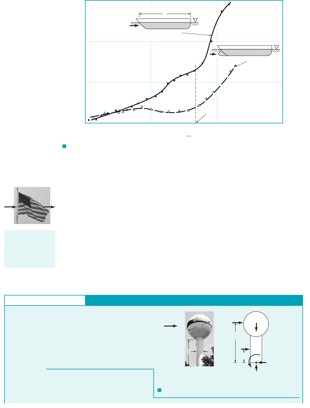
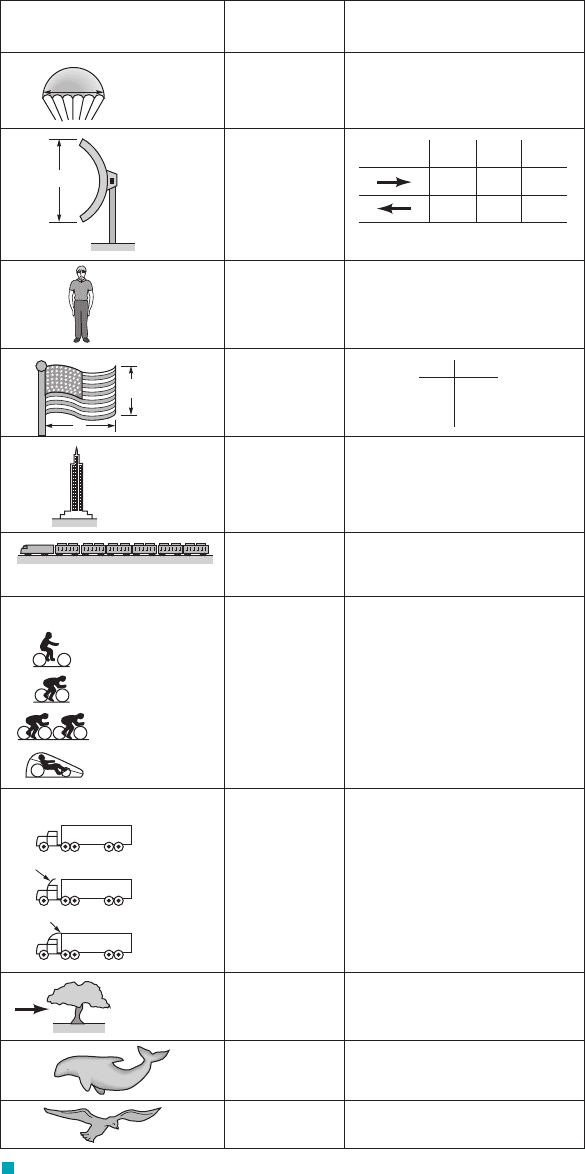
on the Froude number shown is typical. It results from the fact that the struc-
ture of the waves produced by the hull is a strong function of the ship speed or, in dimensionless
form, the Froude number. This wave structure is also a function of the body shape. For example,
the bow wave, which is often the major contributor to the wave drag, can be reduced by use of an
appropriately designed bulb on the bow, as is indicated in Fig. 9.26. In this instance the stream-
lined body 1hull without a bulb2has more drag than the less streamlined one.
Composite Body Drag. Approximate drag calculations for a complex body can often be
obtained by treating the body as a composite collection of its various parts. For example, the total
force on a flag pole because of the wind (see the figure in the margin) can be approximated by
adding the aerodynamic drag produced by the various components involved—the drag on the flag
and the drag on the pole. In some cases considerable care must be taken in such an approach be-
cause of the interactions between the various parts. It may not be correct to merely add the drag
of the components to obtain the drag of the entire object, although such approximations are often
reasonable.
C
Dw
⫽ d
w
Ⲑ
1rU
2
/
2
Ⲑ
22,
9.3 Drag 507
F I G U R E 9.26 Typical drag coefficient data as a function of Froude number and hull
characteristics for that portion of the drag due to the generation of waves (adapted from Ref. 25).
Design speed, Fr = 0.267
0.30.20.1
Hull with bow bulb
0.4
Hull with no bow bulb
U
U
0.0015
0.0010
0.0005
0
C
D
=
C
D
w
w
__________
U
2
2
1
__
2
ρ
Fr =
U
____
√
g
pole
flag
The drag on a com-
plex body can be
approximated as
the sum of the drag
on its parts.
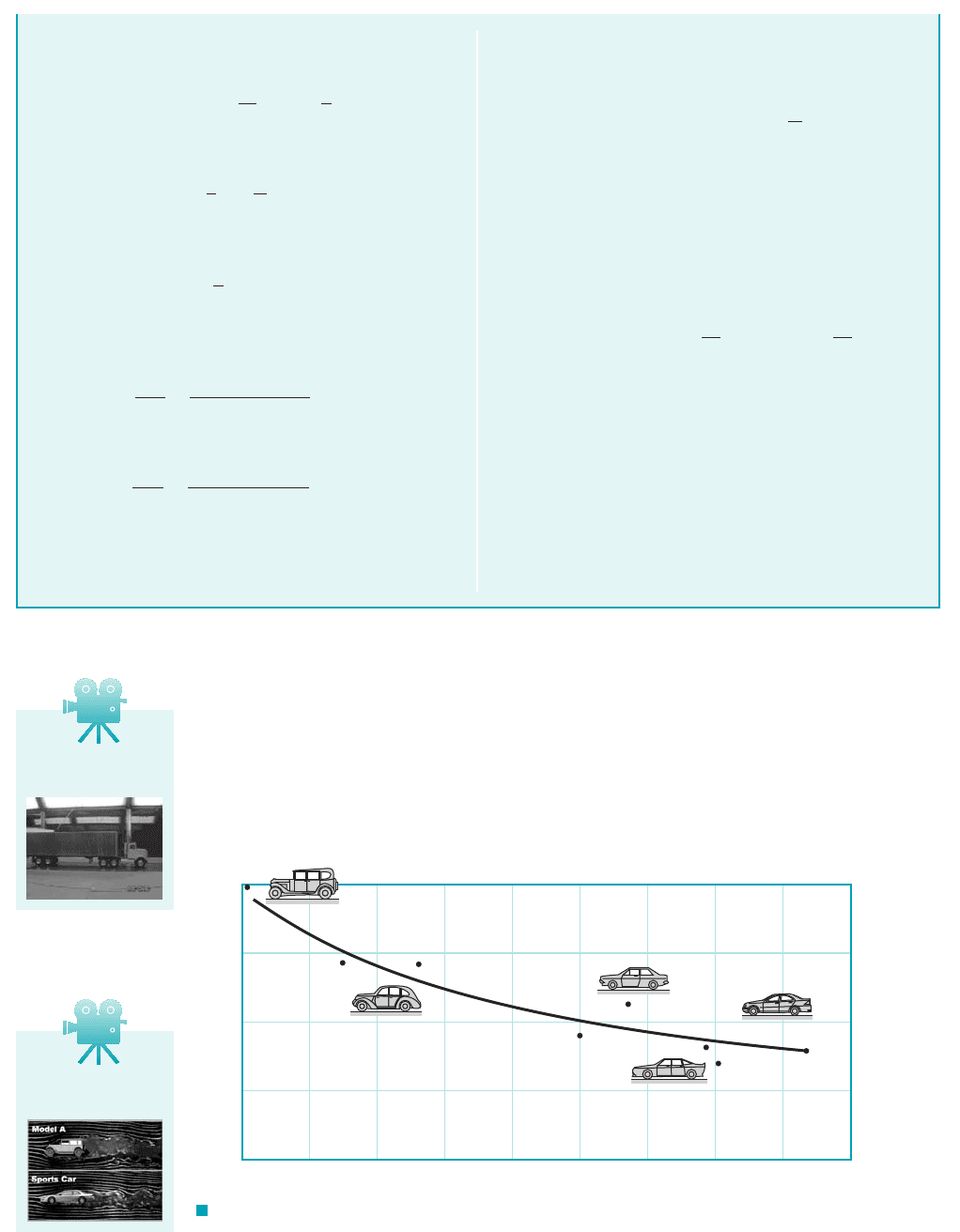
GIVEN A 60-mph 1i.e., 88-fps2wind blows past the water
tower shown in Fig. E9.13a.
FIND Estimate the moment 1torque2, M, needed at the base to
keep the tower from tipping over.
F I G U R E E9.13
Drag on a Composite Body
U = 60 mph
= 88 fps
D
s
= 40 ft
D
c
= 15 ft
b = 50 ft
s
c
b
+ D
s
/2
b/2
R
x
R
y
M
(b)
(
a)
D
c
D
s
b
E
XAMPLE 9.13
S
OLUTION
We treat the water tower as a sphere resting on a circular cylinder
and assume that the total drag is the sum of the drag from these
parts. The free-body diagram of the tower is shown in Fig.
JWCL068_ch09_461-533.qxd 9/23/08 11:48 AM Page 507
The aerodynamic drag on automobiles provides an example of the use of adding component
drag forces. The power required to move a car along a level street is used to overcome the rolling
resistance and the aerodynamic drag. For speeds above approximately 30 mph, the aerodynamic
drag becomes a significant contribution to the net propulsive force needed. The contribution of the
drag due to various portions of car 1i.e., front end, windshield, roof, rear end, windshield peak, rear
roof兾trunk, and cowl2have been determined by numerous model and full-sized tests as well as by
508 Chapter 9 ■ Flow over Immersed Bodies
E9.13b. By summing moments about the base of the tower, we
obtain
(1)
where
(2)
and
(3)
are the drag on the sphere and cylinder, respectively. For standard
atmospheric conditions, the Reynolds numbers are
and
The corresponding drag coefficients, and can be approx-
imated from Fig. 9.21 as
C
Ds
⬇ 0.3
and
C
Dc
⬇ 0.7
C
Dc
,C
Ds
Re
c
⫽
UD
c
n
⫽
188 ft
Ⲑ
s2115 ft2
1.57 ⫻ 10
⫺4
ft
2
Ⲑ
s
⫽ 8.41 ⫻ 10
6
Re
s
⫽
UD
s
n
⫽
188 ft
Ⲑ
s2140 ft2
1.57 ⫻ 10
⫺4
ft
2
Ⲑ
s
⫽ 2.24 ⫻ 10
7
d
c
⫽
1
2
rU
2
bD
c
C
Dc
d
s
⫽
1
2
rU
2
p
4
D
2
s
C
Ds
M ⫽ d
s
ab ⫹
D
s
2
b⫹ d
c
a
b
2
b
Note that the value of was obtained by an extrapolation of the
given data to Reynolds numbers beyond those given 1a potentially
dangerous practice!2. From Eqs. 2 and 3 we obtain
and
From Eq. 1 the corresponding moment needed to prevent the
tower from tipping is
(Ans)
COMMENT The above result is only an estimate because 1a2
the wind is probably not uniform from the top of the tower to the
ground, 1b2the tower is not exactly a combination of a smooth
sphere and a circular cylinder, 1c2the cylinder is not of infinite
length, 1d2there will be some interaction between the flow past
the cylinder and that past the sphere so that the net drag is not ex-
actly the sum of the two, and 1e2a drag coefficient value was ob-
tained by extrapolation of the given data. However, such approxi-
mate results are often quite accurate.
⫽ 3.64 ⫻ 10
5
ft
#
lb
M ⫽ 3470 lb a50 ft ⫹
40
2
ftb⫹ 4840 lb a
50
2
ftb
⫽ 4840 lb
d
c
⫽ 0.510.00238 slugs
Ⲑ
ft
3
2188 ft
Ⲑ
s2
2
150 ft ⫻ 15 ft210.72
⫽ 3470 lb
d
s
⫽ 0.510.00238 slugs
Ⲑ
ft
3
2188 ft
Ⲑ
s2
2
p
4
140 ft2
2
10.32
C
Ds
V9.13 Drag on a
truck
V9.14 Automobile
streamlining
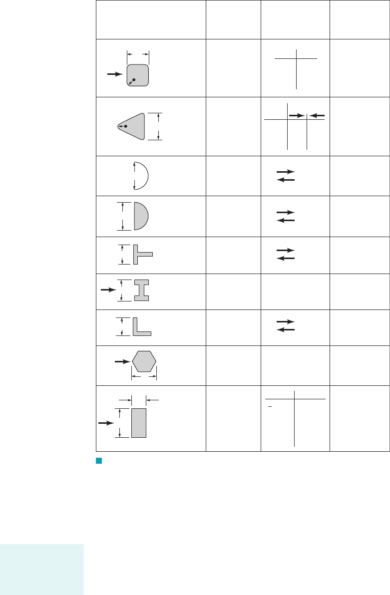
F I G U R E 9.27 The historical trend of streamlining automobiles to reduce their
aerodynamic drag and increase their miles per gallon (adapted from Ref. 5).
0.8
0.6
0.4
0.2
0
1920 1930 1940 1950 1960
Year
1970 1980 1990 2000 2010
C
D
JWCL068_ch09_461-533.qxd 9/23/08 11:48 AM Page 508

numerical calculations. As a result it is possible to predict the aerodynamic drag on cars of a wide
variety of body styles.
As is indicated in Fig. 9.27, the drag coefficient for cars has decreased rather continuously
over the years. This reduction is a result of careful design of the shape and the details 1such as
window molding, rear view mirrors, etc.2. An additional reduction in drag has been accomplished
by a reduction of the projected area. The net result is a considerable increase in the gas mileage,
especially at highway speeds. Considerable additional information about the aerodynamics of
road vehicles can be found in the literature 1Ref. 302.
The effect of several important parameters 1shape, Re, Ma, Fr, and roughness2on the drag co-
efficient for various objects has been discussed in this section. As stated previously, drag coefficient
information for a very wide range of objects is available in the literature. Some of this information
is given in Figs. 9.28, 9.29, and 9.30 below for a variety of two- and three-dimensional, natural and
man-made objects. Recall that a drag coefficient of unity is equivalent to the drag produced by the
dynamic pressure acting on an area of size A. That is, if Typical
nonstreamlined objects have drag coefficients on this order.
C
D
⫽ 1.d ⫽
1
2
rU
2
AC
D
⫽
1
2
rU
2
A
9.4 Lift 509
Fluids in the News
At 10,240 mpg it doesn’t cost much to “fill ’er up” Typical
gas consumption for a Formula 1 racer, a sports car, and a sedan
is approximately 2 mpg, 15 mpg, and 30 mpg, respectively.
Thus, just how did the winning entry in the 2002 Shell Eco-
Marathon achieve an incredible 10,240 mpg? To be sure, this
vehicle is not as fast as a Formula 1 racer (although the rules re-
quire it to average at least 15 mph) and it can’t carry as large a
load as your family sedan can (the vehicle has barely enough
room for the driver). However, by using a number of clever
engineering design considerations, this amazing fuel efficiency
was obtained. The type (and number) of tires, the appropriate
engine power and weight, the specific chassis design, and the
design of the body shell are all important and interrelated con-
siderations. To reduce drag, the aerodynamic shape of the high-
efficiency vehicle was given special attention through theoreti-
cal considerations and wind tunnel model testing. The result is
an amazing vehicle that can travel a long distance without hear-
ing the usual “fill ’er up.” (See Problem 9.90.)
As is indicated in Section 9.1, any object moving through a fluid will experience a net force
of the fluid on the object. For objects symmetrical perpendicular to the upstream flow, this force
will be in the direction of the free stream—a drag, If the object is not symmetrical 1or if it
does not produce a symmetrical flow field, such as the flow around a rotating sphere2, there
may also be a force normal to the free stream—a lift, Considerable effort has been put forth
to understand the various properties of the generation of lift. Some objects, such as an airfoil,
are designed to generate lift. Other objects are designed to reduce the lift generated. For exam-
ple, the lift on a car tends to reduce the contact force between the wheels and the ground, caus-
ing reduction in traction and cornering ability. It is desirable to reduce this lift.
9.4.1 Surface Pressure Distribution
The lift can be determined from Eq. 9.2 if the distributions of pressure and wall shear stress around
the entire body are known. As is indicated in Section 9.1, such data are usually not known. Typi-
cally, the lift is given in terms of the lift coefficient,
(9.39)C
L
⫽
l
1
2
rU
2
A
l.
d.
9.4 Lift
The lift coefficient
is a dimensionless
form of the lift.
Considerable effort
has gone into re-
ducing the aerody-
namic drag of auto-
mobiles.
JWCL068_ch09_461-533.qxd 9/23/08 11:48 AM Page 509
which is obtained from experiments, advanced analysis, or numerical considerations. The lift co-
efficient is a function of the appropriate dimensionless parameters and, as the drag coefficient, can
be written as
The Froude number, Fr, is important only if there is a free surface present, as with an under-
water “wing” used to support a high-speed hydrofoil surface ship. Often the surface roughness,
is relatively unimportant in terms of lift—it has more of an effect on the drag. The Mach
number, Ma, is of importance for relatively high-speed subsonic and supersonic flows
and the Reynolds number effect is often not great. The most important
parameter that affects the lift coefficient is the shape of the object. Considerable effort has gone
into designing optimally shaped lift-producing devices. We will emphasize the effect of the
shape on lift—the effects of the other dimensionless parameters can be found in the literature
1Refs. 13, 14, 292.
1i.e., Ma 7 0.82,
e,
C
L
⫽ f1shape, Re, Ma, Fr, e
Ⲑ
/2
510 Chapter 9 ■ Flow over Immersed Bodies
D
R
Square rod
with rounded
corners
D
R
Rounded
equilateral
triangle
D
Semicircular
shell
Semicircular
cylinder
D
D
T-beam
I-beam
D
D
Angle
D
Hexagon
ᐉ
D
Rectangle
Shape
Reference area
A
(b = length)
A = bD
A
= bD
A
= bD
A
= bD
A
= bD
A
= bD
A
= bD
A
= bD
A
= bD
Drag coefficient
C
D
=
Ᏸ
________
U
2
A
1
__
2
ρ
R/DC
D
0
0.02
0.17
0.33
2.2
2.0
1.2
1.0
R/DC
D
0
0.02
0.08
0.25
1.4
1.2
1.3
1.1
2.1
2.0
1.9
1.3
2.3
1.1
2.15
1.15
1.80
1.65
1.98
1.82
2.05
1.0
ᐉ/DC
D
0.1
0.5
0.65
1.0
2.0
3.0
1.9
2.5
2.9
2.2
1.6
1.3
Reynolds number
Re =
UD/
ρ
Re = 10
5
Re = 10
5
Re = 2 × 10
4
Re > 10
4
Re > 10
4
Re > 10
4
Re > 10
4
Re > 10
4
Re = 10
5
<
μ
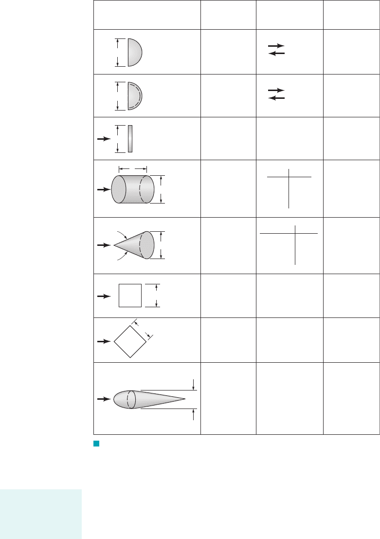
F I G U R E 9.28 Typical drag coefficients for regular two-dimensional
objects (Refs. 5, 6).
The lift coefficient
is a function of
other dimensionless
parameters.
JWCL068_ch09_461-533.qxd 9/23/08 11:49 AM Page 510
Most common lift-generating devices 1i.e., airfoils, fans, spoilers on cars, etc.2operate in the
large Reynolds number range in which the flow has a boundary layer character, with viscous ef-
fects confined to the boundary layers and wake regions. For such cases the wall shear stress,
contributes little to the lift. Most of the lift comes from the surface pressure distribution. A typi-
cal pressure distribution on a moving car is shown in Fig. 9.31. The distribution, for the most part,
is consistent with simple Bernoulli equation analysis. Locations with high-speed flow 1i.e., over
the roof and hood2have low pressure, while locations with low-speed flow 1i.e., on the grill and
windshield2have high pressure. It is easy to believe that the integrated effect of this pressure dis-
tribution would provide a net upward force.
For objects operating in very low Reynolds number regimes viscous effects
are important, and the contribution of the shear stress to the lift may be as important as that of the
pressure. Such situations include the flight of minute insects and the swimming of microscopic or-
ganisms. The relative importance of and p in the generation of lift in a typical large Reynolds
number flow is shown in Example 9.14.
t
w
1i.e., Re 6 12,
t
w
,
9.4 Lift 511
F I G U R E 9.29 Typical drag coefficients for regular three-dimensional
objects (Ref. 5).
D
Solid
hemisphere
D
Hollow
hemisphere
D
Thin disk
ᐉ
D
Circular
rod
parallel
to flow
D
Cone
Cube
D
Cube
D
D
Streamlined
body
Shape
Reference area
A
A
= D
2
__
4
π
A = D
2
__
4
π
A = D
2
__
4
π
A = D
2
__
4
π
A = D
2
__
4
π
A = D
2
A = D
2
A = D
2
__
4
π
Drag coefficient
C
D
1.17
0.42
1.42
0.38
1.1
, degrees C
D
10
30
60
90
0.30
0.55
0.80
1.15
ᐉ/DC
D
0.5
1.0
2.0
4.0
1.1
0.93
0.83
0.85
θ
1.05
0.80
0.04
Re > 10
4
Re > 10
4
Re > 10
3
Re > 10
5
Re > 10
4
Re > 10
4
Re > 10
4
Re > 10
5
Reynolds number
Re =
UD/
ρμ
θ
Usually most lift
comes from pres-
sure forces, not vis-
cous forces.
JWCL068_ch09_461-533.qxd 9/23/08 11:49 AM Page 511
512 Chapter 9 ■ Flow over Immersed Bodies
U
D
Parachute
D
Porous
parabolic
dish
Average
person
Fluttering
flag
D
l
Empire
State Building
Six-car passenger train
Bikes
Upright commuter
Racing
Drafting
Streamlined
Tractor-trailer trucks
Fairing
Gap seal
Standard
With fairing
With
fairing and
gap seal
Tree
U = 10 m/s
U = 20 m/s
U = 30 m/s
Dolphin
Large
birds
Shape Reference area
Frontal area
A =
D
2
__
4
π
Frontal area
A =
D
2
__
4
π
Standing
Sitting
Crouching
A = ᐉD
Frontal area
Frontal area
A = 5.5 ft
2
A = 3.9 ft
2
A = 3.9 ft
2
A = 5.0 ft
2
Frontal area
Frontal area
Frontal area
Frontal area
Frontal area
Wetted area
Drag coefficient
C
D
1.4
Porosity
Porosity = open area/total area
0 0.2 0.5
1.42 1.20 0.82
0.95 0.90 0.80
C
D
A = 9 ft
2
C
D
A = 6 ft
2
C
D
A = 2.5 ft
2
ᐉ/DC
D
2
1
3
0.12
0.07
0.15
1.4
1.8
1.1
0.88
0.50
0.12
0.96
0.76
0.70
0.43
0.26
0.20
0.0036 at Re = 6 × 10
6
(flat plate has C
Df
= 0.0031)
0.40
F I G U R E 9.30 Typical drag coefficients for objects of interest
(Refs. 5, 6, 15, 20).
JWCL068_ch09_461-533.qxd 9/23/08 11:49 AM Page 512

9.4 Lift 513
GIVEN When a uniform wind of velocity U blows past the
semicircular building shown in Fig. E9.14a,b, the wall shear
stress and pressure distributions on the outside of the building are
as given previously in Figs. E9.8b and E9.9a, respectively.
Lift from Pressure and Shear Stress Distributions
E
XAMPLE 9.14
FIND If the pressure in the building is atmospheric 1i.e., the
value, far from the building2, determine the lift coefficient and
the lift on the roof.
p
0
,
S
OLUTION
curves of and
plotted in Figs. E9.14c and E9.14d. The results are
and
Thus, the lift is
or
(Ans)
and
(4)
(Ans)
COMMENTS Consider a typical situation with
and standard atmospheric conditions
which
gives a Reynolds number of
Hence, the lift coefficient is
C
L
⫽ 0.88 ⫹
1.96
13.82 ⫻ 10
6
2
1
Ⲑ
2
⫽ 0.88 ⫹ 0.001 ⫽ 0.881
Re ⫽
UD
n
⫽
130 ft
Ⲑ
s2120 ft2
1.57 ⫻ 10
⫺4
ft
2
Ⲑ
s
⫽ 3.82 ⫻ 10
6
⫻ 10
⫺4
ft
2
Ⲑ
s2,10
⫺3
slugs
Ⲑ
ft
3
and n ⫽ 1.571r ⫽ 2.38 ⫻
b ⫽ 50 ft,U ⫽ 30 ft
Ⲑ
s,
D ⫽ 20 ft,
C
L
⫽
l
1
2
rU
2
A
⫽ 0.88 ⫹
1.96
1Re
l ⫽ a0.88 ⫹
1.96
1Re
b a
1
2
rU
2
Ab
l ⫽
1
2
rU
2
A ca⫺
1
2
b 1⫺1.762⫹
1
21Re
13.922d
冮
p
0
F1u2 cos u du ⫽ 3.92
冮
p
0
1p ⫺ p
0
2
1
2
rU
2
sin u du ⫽⫺1.76
versus u
F1u2 cos usin u versus u31p ⫺ p
0
2
Ⲑ
1rU
2
Ⲑ
224
From Eq. 9.2 we obtain the lift as
(1)
As is indicated in Fig. E9.14b, we assume that on the inside of the
building the pressure is uniform, and that there is no
shear stress. Thus, Eq. 1 can be written as
or
(2)
where b and D are the length and diameter of the building,
respectively, and Equation 2 can be put into
dimensionless form by using the dynamic pressure, plan-
form area, and dimensionless shear stress
to give
(3)
From the data in Figs. E9.8b and E9.9a, the values of the two in-
tegrals in Eq. 3 can be obtained by determining the area under the
⫹
1
21Re
冮
p
0
F1u2 cos u du d
l ⫽
1
2
rU
2
A c⫺
1
2
冮
p
0
1p ⫺ p
0
2
1
2
rU
2
sin u du
F1u2⫽ t
w
1Re2
1
Ⲑ
2
Ⲑ
1rU
2
Ⲑ
22
A ⫽ bD,
rU
2
Ⲑ
2,
dA ⫽ b1D
Ⲑ
22du.
l ⫽
bD
2
c⫺
冮
p
0
1p ⫺ p
0
2 sin u du ⫹
冮
p
0
t
w
cos u du d
⫹
冮
p
0
t
w
cos u b a
D
2
b du
l ⫽⫺
冮
p
0
1p ⫺ p
0
2 sin u b a
D
2
b du
p ⫽ p
0
,
l ⫽⫺
冮
p sin u dA ⫹
冮
t
w
cos u dA
U, p
0
Denotes p > p
0
Denotes p < p
0
F I G U R E 9.31 Pressure distribution on the surface of
an automobile.
JWCL068_ch09_461-533.qxd 9/23/08 11:49 AM Page 513
514 Chapter 9 ■ Flow over Immersed Bodies
A typical device designed to produce lift does so by generating a pressure distribution that
is different on the top and bottom surfaces. For large Reynolds number flows these pressure dis-
tributions are usually directly proportional to the dynamic pressure, with viscous effects
being of secondary importance. Hence, as indicated by the figure in the margin, for a given airfoil
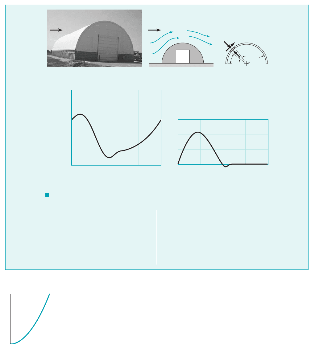
the lift is proportional to the square of the airspeed. Two airfoils used to produce lift are indicated
in Fig. 9.32. Clearly the symmetrical one cannot produce lift unless the angle of attack, is nonzero.
Because of the asymmetry of the nonsymmetric airfoil, the pressure distributions on the upper and
lower surfaces are different, and a lift is produced even with Of course, there will be a
certain value of 1less than zero for this case2for which the lift is zero. For this situation, the
pressure distributions on the upper and lower surfaces are different, but their resultant 1integrated2
pressure forces will be equal and opposite.
Since most airfoils are thin, it is customary to use the planform area, in the defini-
tion of the lift coefficient. Here b is the length of the airfoil and c is the chord length—the length
from the leading edge to the trailing edge as indicated in Fig. 9.32. Typical lift coefficients so de-
fined are on the order of unity. That is, the lift force is on the order of the dynamic pressure times
the planform area of the wing, The wing loading, defined as the average lift per
unit area of the wing, therefore, increases with speed. For example, the wing loading of thel
Ⲑ
A,
l ⬇ 1rU
2
Ⲑ
22A.
A ⫽ bc,
a
a ⫽ 0.
a,
rU
2
Ⲑ
2,
Note that the pressure contribution to the lift coefficient is
0.88 whereas that due to the wall shear stress is only
The Reynolds number dependency of is
quite minor. The lift is pressure dominated. Recall from Example
9.9 that this is also true for the drag on a similar shape.
From Eq. 4 with , we obtain the
lift for the assumed conditions as
l ⫽
1
2
rU
2
AC
L
⫽
1
2
10.00238 slugs
Ⲑ
ft
3
2130 ft
Ⲑ
s2
2
11000 ft
2
210.8812
A ⫽ 20 ft ⫻ 50 ft ⫽ 1000 ft
2
C
L
1.96
Ⲑ
1Re
1
Ⲑ
2
2⫽ 0.001.
or
There is a considerable tendency for the building to lift off the
ground. Clearly this is due to the object being nonsymmetrical.
The lift force on a complete circular cylinder is zero, although
the fluid forces do tend to pull the upper and lower halves
apart.
l ⫽ 944 lb
U
ᏸ
ᏸ ~ U
2
d
w
dA
p
0
dA
pdA
D
/2
θ
τ
θ
U
p
0
(b)(a)
(
c)(d)
1.0
0.5
0
–0.5
–1.0
–1.5
0
C
p
sin =
θ
sin
θ
p – p
0
_______
U
2
1
__
2
ρ
π
__
4
π
__
2
3
___
4
π
0
0
2
4
6
π
__
4
π
__
2
π
3
___
4
π
θ
, rad
θ
, rad
F( ) cos
θθ
π
U
p
0
F I G U R E E9.14
JWCL068_ch09_461-533.qxd 9/23/08 11:49 AM Page 514
1903 Wright Flyer aircraft was while for the present-day Boeing 747 aircraft it is
The wing loading for a bumble bee is approximately 1Ref. 152.
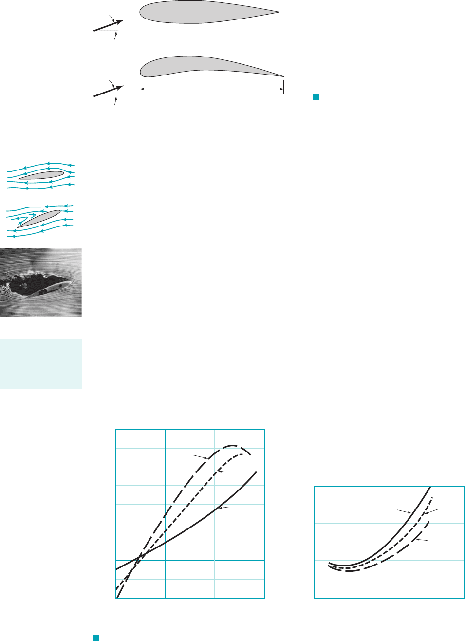
Typical lift and drag coefficient data as a function of angle of attack, and aspect ratio,
are indicated in Figs. 9.33a and 9.33b. The aspect ratio is defined as the ratio of the square of the
wing length to the planform area, If the chord length, c, is constant along the length of
the wing 1a rectangular planform wing2, this reduces to
In general, the lift coefficient increases and the drag coefficient decreases with an increase
in aspect ratio. Long wings are more efficient because their wing tip losses are relatively more mi-
nor than for short wings. The increase in drag due to the finite length of the wing is of-
ten termed induced drag. It is due to the interaction of the complex swirling flow structure near
the wing tips 1see Fig. 9.372and the free stream 1Ref. 132. High-performance soaring airplanes and
highly efficient soaring birds 1i.e., the albatross and sea gull2have long, narrow wings. Such wings,
however, have considerable inertia that inhibits rapid maneuvers. Thus, highly maneuverable fighter
or acrobatic airplanes and birds 1i.e., the falcon2have small-aspect-ratio wings.
Although viscous effects and the wall shear stress contribute little to the direct generation of
lift, they play an extremely important role in the design and use of lifting devices. This is because of
the viscosity-induced boundary layer separation that can occur on nonstreamlined bodies such as
airfoils that have too large an angle of attack 1see Fig. 9.182. As is indicated in Fig. 9.33, up to a cer-
tain point, the lift coefficient increases rather steadily with the angle of attack. If is too large, the
boundary layer on the upper surface separates, the flow over the wing develops a wide, turbulent
wake region, the lift decreases, and the drag increases. This condition, as indicated by the figures in
the margin, is termed stall. Such conditions are extremely dangerous if they occur while the airplane
is flying at a low altitude where there is not sufficient time and altitude to recover from the stall.
a
1a 6 2
a b
c.
a b
2
A.
a,a,
1 lb
ft
2
150 lb
ft
2
.
1.5 lb
ft
2
,
9.4 Lift 515
α
U
Symmetrical
Nonsymmetrical
c
α
U
F I G U R E 9.32 Symmetrical and
nonsymmetrical airfoils.
–0.4
–10 0 10
, degrees
(
a)(b)
α
, degrees
α
20
–0.2
0
0.2
0.4
0.6
0.8
1.0
1.2
1.4
C
L
C
D
= 7
= 3
= 1
= 1 = 3
= 7
0.03
0.02
0.01
0
–10 0 10 20
F I G U R E 9.33 Typical lift and drag coefficient data as a function of angle of attack and the
aspect ratio of the airfoil: (a) lift coefficient, (b) drag coefficient.
Not stalled
Stalled
At large angles of
attack the boundary
layer separates and
the wing stalls.
JWCL068_ch09_461-533.qxd 9/23/08 11:49 AM Page 515
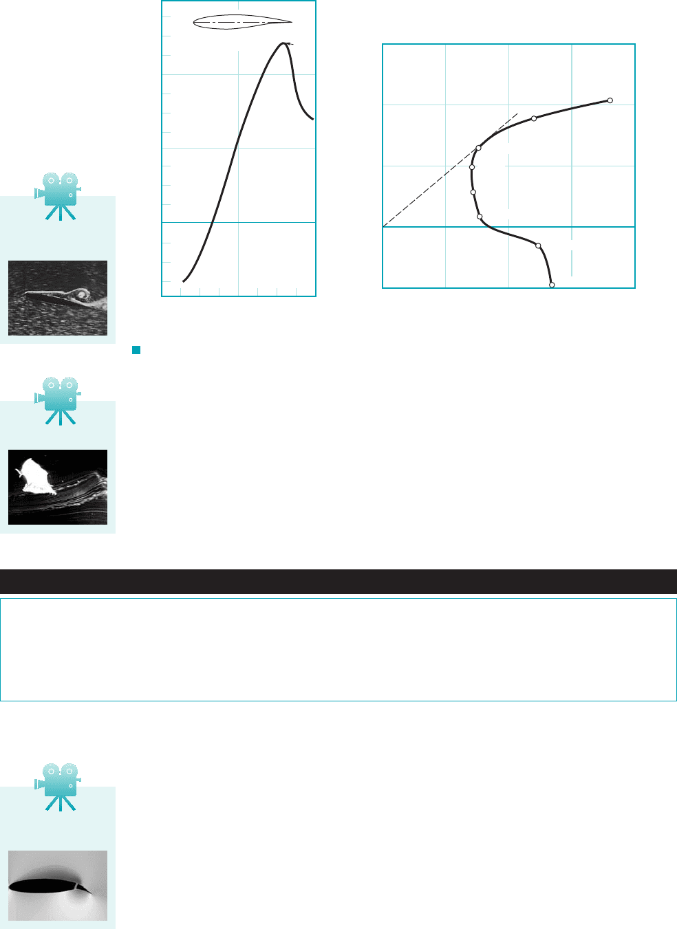
In many lift-generating devices the important quantity is the ratio of the lift to drag devel-
oped, Such information is often presented in terms of versus as is shown
in Fig. 9.34a, or in a lift-drag polar of versus with as a parameter, as is shown in Fig.
9.34b. The most efficient angle of attack 1i.e., largest 2can be found by drawing a line tan-
gent to the curve from the origin, as is shown in Fig. 9.34b. High-performance airfoils
generate lift that is perhaps 100 or more times greater than their drag. This translates into the fact
that in still air they can glide a horizontal distance of 100 m for each 1 m drop in altitude.
C
L
⫺ C
D
C
L
Ⲑ
C
D
aC
D
C
L
a,C
L
Ⲑ
C
D
l
Ⲑ
d ⫽ C
L
Ⲑ
C
D
.
As is indicated above, the lift and drag on an airfoil can be altered by changing the angle
of attack. This actually represents a change in the shape of the object. Other shape changes can
be used to alter the lift and drag when desirable. In modern airplanes it is common to utilize lead-
ing edge and trailing edge flaps as is shown in Fig. 9.35. To generate the necessary lift during
the relatively low-speed landing and takeoff procedures, the airfoil shape is altered by extending
special flaps on the front and兾or rear portions of the wing. Use of the flaps considerably enhances
the lift, although it is at the expense of an increase in the drag 1the airfoil is in a “dirty” config-
uration2. This increase in drag is not of much concern during landing and takeoff operations—
the decrease in landing or takeoff speed is more important than is a temporary increase in drag.
During normal flight with the flaps retracted 1the “clean” configuration2, the drag is relatively
small, and the needed lift force is achieved with the smaller lift coefficient and the larger dynamic
pressure 1higher speed2.
516 Chapter 9 ■ Flow over Immersed Bodies
F I G U R E 9.34 Two representations of the same lift and drag data for a typical airfoil:
(a) lift-to-drag ratio as a function of angle of attack, with the onset of boundary layer separation on the
upper surface indicated by the occurrence of stall, (b) the lift and drag polar diagram with the angle of
attack indicated (Ref. 27).
120
100
80
60
40
20
0
–20
–40
–8 –4 0 4 8
, degrees
α
C
L
__
C
D
NACA 64(1) – 412 airfoil
Re = 7 × 10
5
Stall
1.5
1.0
0.5
0
–0.5
0 0.005 0.010 0.015 0.02
C
D
C
L
(b)(a)
= –6°
α
= –4°
α
= –2°
α
= 0°
α
= 2°
α
= 4°
α
= 6°
α
= 8°
α
V9.16 Bat flying
Fluids in the News
Bats feel turbulence Researchers have discovered that at certain
locations on the wings of bats, there are special touch-sensing
cells with a tiny hair poking out of the center of the cell. These cells,
which are very sensitive to air flowing across the wing surface, can
apparently detect turbulence in the flow over the wing. If these hairs
are removed the bats fly well in a straight line, but when maneuver-
ing to avoid obstacles, their elevation control is erratic. When the
hairs grow back, the bats regain their complete flying skills. It is pro-
posed that these touch-sensing cells are used to detect turbulence on
the wing surface and thereby tell bats when to adjust the angle of at-
tack and curvature of their wings in order to avoid stalling out in
midair.
V9.15 Stalled
airfoil
V9.17 Trailing edge
flap
JWCL068_ch09_461-533.qxd 9/23/08 11:49 AM Page 516