Neamen D. Microelectronics: Circuit Analysis and Design
Подождите немного. Документ загружается.

938 Part 2 Analog Electronics
the small-signal parameters for Q
1
and Q
2
. (b) Using nodal analysis,
determine the small-signal closed-loop current gain
A
if
= i
o
/i
s
. (c) Using
nodal analysis, find the input resistance
R
if
.
*12.50 (a) Using the small-signal equivalent circuit in Figure 12.25 for the cir-
cuit in Figure 12.24(a), derive the expression for the small-signal current
gain
A
if
= I
o
/I
s
. (b) Using the circuit parameters given in Figure
12.24(a) and assuming transistor parameters
h
FE
= 100
and
V
A
=∞
,
calculate the value of
A
if
. Compare this answer with the results of
Example 12.9.
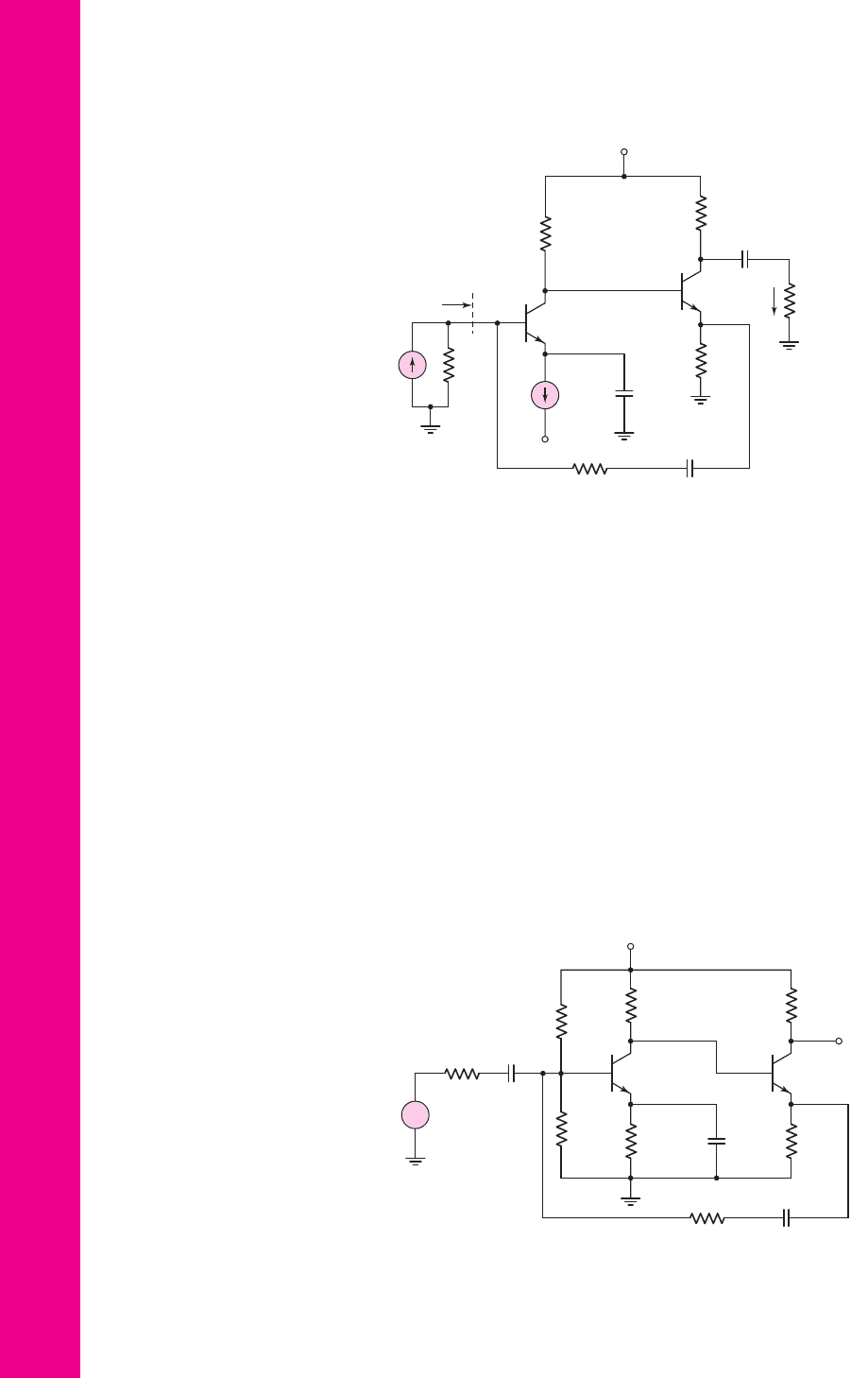
*12.51 The circuit in Figure P12.51 is an example of a shunt–series feedback circuit.
A signal proportional to the output current is fed back to the shunt connection
at the base of Q
1
. However, the circuit may be used as a voltage amplifier.
Assume transistor parameters of
h
FE
= 120
,
V
BE
(on) = 0.7
V, and
V
A
=∞
. (a) Determine the small-signal parameters for Q
1
and Q
2
. (b) Using
nodal analysis, determine the small-signal voltage gain
A
v
= v
o
/v
s
.
V
+
= +10 V
V
–
= –10 V
R
F
= 10 kΩ
R
C1
= 40 kΩ
R
L
=
0.5 kΩ
R
S
=
10 kΩ
I
E1
=
0.2 mA
R
E
=
1 kΩ
R
C2
= 2 kΩ
Q
2
Q
1
R
if
C → ∞
C → ∞
C → ∞
i
s
i
o
Figure P12.49
V
CC
= 10 V
R
F
= 1.2 kΩ
R
S
= 0.6 kΩ
R
E1
=
1 kΩ
R
C1
= 3 kΩ
R
E2
=
8.1 kΩ
R
C2
= 4 kΩ
R
1
=
38.3 kΩ
R
2
=
13.5 kΩ
Q
1
Q
2
C
C
→ ∞
C
F
→ ∞
C
E
→ ∞
v
s
v
o
+
–
Figure P12.51
nea80644_ch12_851-946.qxd 6/23/09 1:45 PM Page 938 pmath DATA-DISK:Desktop Folder:23/06/09:MHDQ134-12:
Chapter 12 Feedback and Stability 939
12.52 Consider the circuit in Figure P12.51 with transistor parameters,
h
FE
= 120
,
V
BE
(on) = 0.7
V, and
V
A
=∞
. Using nodal analysis, deter-
mine the input resistance
R
if
.
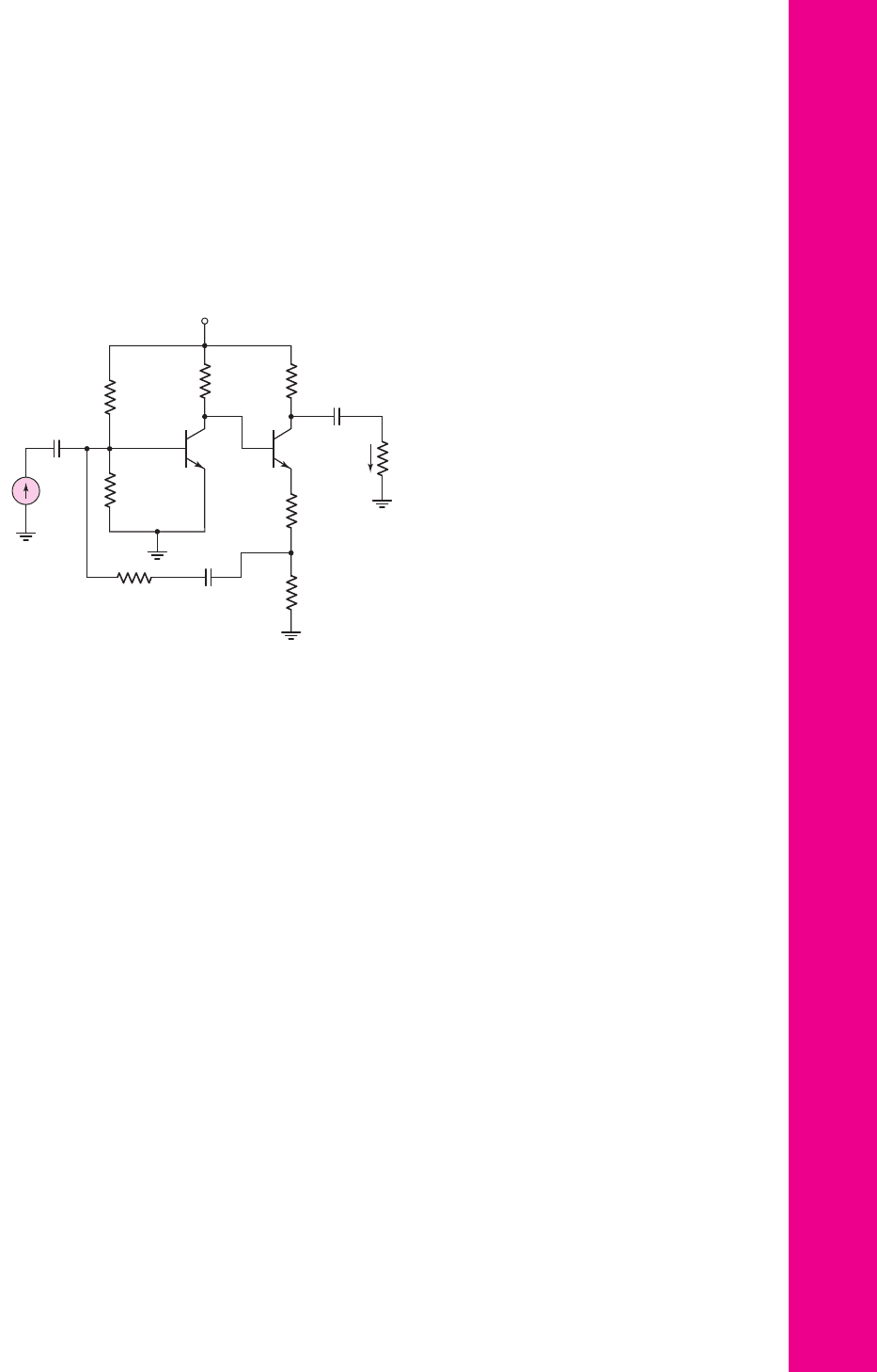
12.53 For the transistors in the circuit in Figure P12.53, the parameters are:
h
FE
= 50
,
V
BE
(on) = 0.7
V, and
V
A
=∞
. Using nodal analysis, deter-
mine the closed-loop current gain
A
if
= i
o
/i
s
.
V
CC
= 10 V
R
F
= 5 kΩ
R
C1
=
7 kΩ
R
1
=
17.9 kΩ
R
2
=
1.4 kΩ
R
C2
= 2.2 kΩ
R
E1
=
250 Ω
R
E2
= 500 Ω
Q
1
Q
2
C → ∞
C → ∞
C → ∞
R
L
= 2 kΩ
i
s
i
o
Figure P12.53
*D12.54 Design a discrete transistor feedback current amplifier to provide a current
gain of 30. Assume the available transistors have parameters
h
FE
= 120
and
V
A
=∞
. The signal current source has a source resistance of
R
S
= 25 k
and the load is
R
L
= 500
. Verify the design with a com-
puter simulation. Determine
R
if
and
R
of
.
Section 12.6 Transconductance (Series–Series) Amplifiers
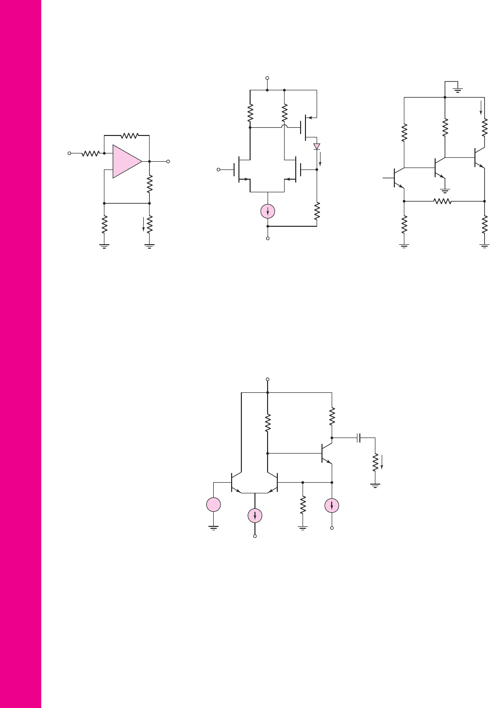
12.55 Consider the transconductance amplifier shown in Figure P12.55. Assume
the op-amp is ideal. (a) Derive the expression for the transconductance
function
A
gf
= I
o
/V
i
. (b) If the circuit is designed such that
R
F
/R
1
=
R
3
/R
2
, show that
I
o
/V
i
=−1/R
2
. (c) Design the circuit such that
I
o
/V
i
=−0.5
mA/V.
12.56 Consider the transconductance feedback amplifier shown in Figure P12.56
with
R
D
= 1.6k
and
R
L
= 248
. The transistor parameters are
V
TN
= 0.5
V,
V
TP
=−0.5
V,
K
n
= 2
mA/V
2
,
K
p
= 10
mA/V
2
, and
λ
n
=
λ
p
= 0
. The LED turn-on voltage is
V
γ
= 1.6
V. Assume the LED small-
signal resistance is
r
f
= 0
. The current source is ideal. (a) Determine the
quiescent values of
V
D1
,
I
DQ3
and
V
G2
. (b) Derive the small-signal transcon-
ductance function
A
gf
= I
o
/V
i
. (c) Calculate the value of
A
gf
= I
o
/V
i
.
12.57 The circuit in Figure P12.57 is the ac equivalent circuit of a series–series
feedback amplifier. Assume that the bias circuit, which is not shown, results
in quiescent collector currents of
I
C1
= 0.5
mA,
I
C2
= 1
mA, and
I
C3
=
2 mA. Assume transistor parameters of
h
FE
= 120
and
r
o
=∞
. Determine
the transconductance transfer function
A
gf
= I
o
/V
s
.
nea80644_ch12_851-946.qxd 6/23/09 1:45 PM Page 939 pmath DATA-DISK:Desktop Folder:23/06/09:MHDQ134-12:
940 Part 2 Analog Electronics
D12.58 Using a computer simulation analysis, redesign the circuit in Figure P12.57
by changing the value of R
F
to achieve a transconductance gain of
A
gf
=
I
o
/V
s
= 120 mA/V
.
12.59 In the circuit in Figure P12.59, the transistor parameters are:
h
FE
= 100
,
V
BE
(on) = 0.7
V, and
V
A
=∞
. Determine the transconductance transfer
function
A
gf
= i
o
/v
s
.
R
D
R
D
R
L
V
+
= 3 V
M
1
M
2
I
Q
=
2 mA
V
i
M
3
D
I
o
V
–
= –3 V
Figure P12.56
R
F
= 0.8 kΩ
R
C1
= 5 kΩ
R
C2
=
2 kΩ
R
C3
=
1 kΩ
R
E2
= 0.1 kΩ
R
E1
= 0.1 kΩ
Q
2
Q
1
Q
3
V
s
I
o
Figure P12.57
R
L
=
1 kΩ
R
C2
= 18.6 kΩ
R
C3
= 2 kΩ
Q
1
Q
2
Q
3
1 mA
2 mA
R
F
= 10 kΩ
V
+
= 10 V
V
–
V
–
C → ∞
v
s
i
o
+
–
Figure P12.59
V
o
V
i
R
2
R
1
R
L
V
L
R
3
R
F
+
–
I
o
Figure P12.55
D12.60 Design a feedback amplifier to supply a current to an LED. Use the config-
uration shown in Figure 12.27 where
R
L
is replaced by the LED. (a) As-
suming an ideal op-amp is available, design the circuit such that the diode
current is
I
O
= 3 ×10
−3
V
i
where
V
i
is in the range 0 to 5 V. (b) If
V
i
= 5
V,
what is the error in diode current if the op-amp has a finite gain of
A
g
= 10
3
mA/V and
h
FE
= 80
?
nea80644_ch12_851-946.qxd 6/23/09 1:45 PM Page 940 pmath DATA-DISK:Desktop Folder:23/06/09:MHDQ134-12:
Section 12.7 Transresistance (Shunt–Shunt) Amplifiers
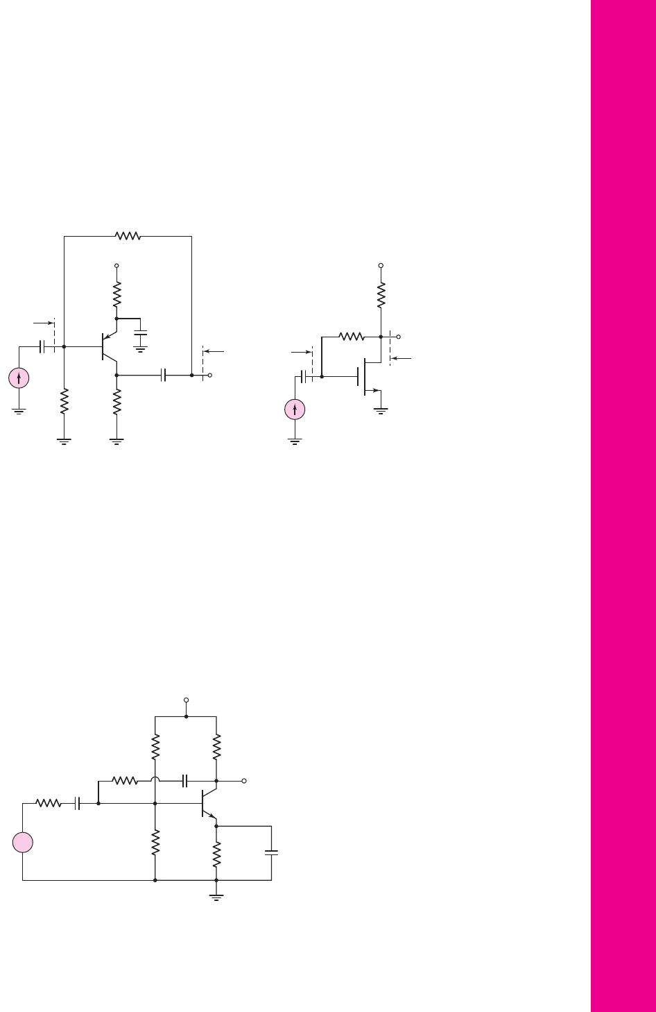
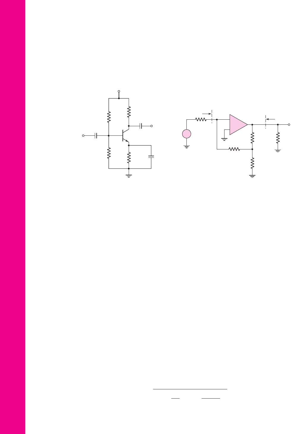
12.61 Consider the common-emitter circuit in Figure P12.61 driven by an ideal sig-
nal current source. The transistor parameters are
h
FE
= 80
,
V
EB
(
on
)
= 0.7
V,
and
V
A
= 100
V. (a) Determine the quiescent values
I
CQ
and
V
ECQ
. (b) Find
the transresistance transfer function
A
zf
= v
o
/i
s
. (c) Determine the input
resistance
R
if
. (d) Find the output resistance
R
of
.
Chapter 12 Feedback and Stability 941
12.62 The transistor parameters for the circuit shown in Figure P12.62 are
V
TN
=
0.4
V,
K
n
= 0.5
mA/V
2
, and
λ = 0
. (a) Find (i) the quiescent drain current
I
DQ
and (ii) the small-signal transistor parameters. (b) Determine the transre-
sistance transfer function
A
zf
= v
o
/i
s
. (c) Find the output resistance
R
of
.
12.63 Consider Problem 12.62. (a) What is the magnitude of the ideal transresis-
tance transfer function
A
zf
as the transistor transconductance parameter
g
m
→∞
. (b) Determine the value of
g
m
so that
A
zf
is within 95 percent
of the ideal magnitude.
12.64 For the circuit in Figure P12.64, the transistor parameters are:
h
FE
= 150
,
V
BE
(on) = 0.7
V, and
V
A
=∞
. Determine the value of R
F
that will result
in a closed-loop voltage gain of
A
v
= V
o
/V
s
=−5.0
.
Figure P12.61
R
E
=
0.5 kΩ
R
C
=
1 kΩ
R
F
= 10 kΩ
R
B
=
100 kΩ
i
s
V
+
= 5 V
R
if
v
o
R
o
f
C
C1
→ ∞
C
E
→ ∞
C
C2
→ ∞
R
D
=
5 kΩ
R
F
= 25 kΩ
i
s
R
if
R
o
f
V
+
= 3 V
v
o
C
C
Figure P12.62
V
s
V
o
V
CC
= 12 V
R
S
= 5 kΩ
R
F
R
E
=
1 kΩ
R
C
= 6 kΩ
R
1
=
150 kΩ
R
2
=
24 kΩ
C → ∞
C → ∞
C
E
→ ∞
+
–
Figure P12.64
nea80644_ch12_851-946.qxd 6/23/09 1:45 PM Page 941 pmath DATA-DISK:Desktop Folder:23/06/09:MHDQ134-12:
12.65 Consider the three-stage cascade feedback circuit in Figure l2.41. Each
stage corresponds to the circuit in Figure P12.65, with transistor parame-
ters:
h
FE
= 180
,
V
BE
(on) = 0.7
V, and
V
A
=∞
. The source resistor is
R
S
= 10 k
, and the load resistor is
R
L
= 4k
. Determine the value of R
F
such that the closed-loop gain is
A
v
= v
o
/v
i
=−80
.
942 Part 2 Analog Electronics
V
s
V
o
R
if
R
of
R
L
= 4 kΩ
R
F
= 10 kΩ
R
S
= 5 kΩ
R
1
=
50 kΩ
R
2
= 10 kΩ
+
–
–
+
Figure P12.66
12.66 The op-amp in the circuit in Figure P12.66 has an open-loop differential
voltage gain of
A
d
= 10
4
. Neglect the current into the op-amp, and assume
the output resistance looking back into the op-amp is zero. Determine:
(a) the closed-loop voltage gain
A
v
= V
o
/V
s
, (b) the input resistance
R
if
,
and (c) the output resistance
R
of
.
D12.67 Design a feedback transresistance amplifier using an op-amp with parame-
ters
R
i
= 10 k
,
R
o
= 100
, and a low-frequency open-loop gain of
A
v
= 10
4
to produce a gain of
5k
. The source resistance is
R
S
= 500
and the load resistance is
R
L
= 2k
. Determine the actual gain, input
resistance, and output resistance using a computer simulation.
Section 12.8 Loop Gain
12.68 The op-amp in Figure 12.20 has an open-loop differential input resistance R
i
,
an open-loop current gain A
i
, and a zero output resistance. Break the feed-
back loop at an appropriate point, and derive the expression for the loop gain.
12.69 The small-signal parameters of the transistors in the circuit in Figure P12.37
are h
FE
and
V
A
=∞
. Derive the expression for the loop gain.
12.70 Determine the loop gain T for the circuit in Figure P12.49. The transistor
parameters are:
h
FE
= 100
,
V
BE
(on) = 0.7
V, and
V
A
=∞
.
12.71 The transistor parameters for the circuit shown in Figure P12.64 are:
h
FE
= 50
,
V
BE
(on) = 0.7
V, and
V
A
= 100
V. Find the loop gain T.
Section 12.9 Stability of the Feedback Circuit
12.72 A three-pole feedback amplifier has a loop gain given by
T
(
f
)
=
β
5 × 10
4
1 + j
f
10
3
1 + j
f
5 × 10
4
2
12 V
8 kΩ
4 kΩ
15 kΩ
4 kΩ
C → ∞
C → ∞
C → ∞
…
…
Figure P12.65
nea80644_ch12_851-946.qxd 6/23/09 1:45 PM Page 942 pmath DATA-DISK:Desktop Folder:23/06/09:MHDQ134-12:

(a) Determine the frequency
f
180
at which the phase is
−
180 degrees. (b) At
the frequency
f
180
, determine the value of
β
such that
|
T ( f
180
)
|
= 0.25
.
12.73 The open-loop voltage gain of an amplifier is given by
A
v
=
10
4
1 + j
f
5 × 10
3
2
1 + j
f
5 × 10
5
(a) Assuming the feedback transfer function is not a function of frequency,
determine the frequency at which the phase of the loop gain is 180 degrees.
(b) At what value of
β
will the feedback amplifier become unstable? (c) Using
the value of
β
found in part (b), what is the low-frequency closed-loop
gain? (d) Is the closed-loop feedback system stable for smaller or larger
values of
β
?
12.74 A loop gain function is given by
T ( f ) =
β(10
3
)
1 + j
f
10
4
1 + j
f
5 × 10
4
1 + j
f
10
5
Sketch the Nyquist plot for: (a)
β = 0.005
, and (b)
β = 0.05
. (c) Is the
system stable or unstable in each case?
12.75 A three-pole feedback amplifier has a loop gain function given by
T ( f ) =
β(5 ×10
3
)
1 + j
f
10
3
2
1 + j
f
5 × 10
4
(a) Sketch the Nyquist diagram for
β = 0.20
. (b) Determine the value of
β
that produces a phase margin of 80 degrees.
12.76 A three-pole feedback amplifier has a loop gain given by
T ( f ) =
β(10
4
)
1 + j
f
10
3
1 + j
f
10
4
1 + j
f
10
5
Sketch Bode plots of the loop gain magnitude and phase for: (a)
β = 0.005
,
and (b)
β = 0.05
. (c) Is the system stable or unstable in each case? If the
system is stable, what is the phase margin?
12.77 A feedback system has an amplifier with a low-frequency open-loop gain of
5 × 10
4
and has poles at
10
3
Hz,
10
5
Hz, and
10
7
Hz. (a) Determine the fre-
quency
f
180
at which the phase of the loop gain is 180 degrees. (b) Deter-
mine the feedback transfer function
β
for which the phase margin of the
system is
45
◦
. (c) Using the results of part (b), determine the low-frequency
closed-loop gain.
12.78 The open-loop voltage gain of an amplifier is given by
A
v
=
10
5
1 + j
f
10
3
1 + j
f
10
5
(a) If the low-frequency, closed-loop gain is 100, is this amplifier stable?
(b) If so, determine the phase margin.
Chapter 12 Feedback and Stability 943
nea80644_ch12_851-946.qxd 6/23/09 1:45 PM Page 943 pmath DATA-DISK:Desktop Folder:23/06/09:MHDQ134-12:

12.79 The loop gain function of a feedback system is described by
T
(
f
)
=
β
10
3
1 + j
f
10
4
1 + j
f
10
5
1 + j
f
10
6
(a) Determine the frequency
f
180
at which the phase of
T ( f )
is
−180
degrees. (b) For
β = 0.019
, (i) find
|
T ( f
180
)
|
and (ii) find the phase at which
|
T
|
= 1
. (c) Using the results of part (b), determine the low-frequency
closed-loop gain
A
f
(0)
.
12.80 Consider a feedback amplifier for which the open-loop gain is given by
A( f ) =
2 × 10
3
1 + j
f
5 × 10
3
1 + j
f
10
5
2
(a) Determine the frequency f
180
at which the phase of
A( f )
is
−180
de-
grees. (b) For
β = 0.0045
, determine the magnitude of the loop gain
T ( f )
at the frequency
f = f
180
and determine the phase of
A( f )
when
|T ( f )|=1
.
Determine the closed-loop, low-frequency gain. Is the system stable or
unstable? (c) Repeat part (b) for
β = 0.15
.
12.81 Consider a four-pole feedback system with a loop gain given by
T ( f ) =
β(10
3
)
1 + j
f
10
3
1 + j
f
10
4
1 + j
f
10
5
1 + j
f
10
6
Determine the value of
β
that produces a phase margin of 45 degrees.
Section 12.10 Frequency Compensation
12.82 A feedback amplifier has a low-frequency open-loop gain of 4000 and three
poles at
f
P1
= 400
kHz,
f
P2
= 4
MHz, and
f
P3
= 40
MHz. A dominant
pole is to be inserted such that the phase margin is 60 degrees. Assuming the
original poles remain fixed, determine the dominant pole frequency.
12.83 The loop gain of a three-pole amplifier is given by
T ( f ) =
10
3
1 + j
f
10
4
2
1 + j
f
10
6
(a) Show that this function will lead to an unstable feedback system. (b) Insert
a dominant pole such that the phase margin is 45 degrees. Assume the orig-
inal poles remain fixed. What is the dominant pole frequency.
12.84 A loop gain function is given by
T ( f ) =
500
1 + j
f
10
4
1 + j
f
5 × 10
4
1 + j
f
10
5
(a) Determine the frequency f
180
(to a good approximation) at which the
phase of T( f ) is
−180
degrees. (b) What is the magnitude of T( f ) at the fre-
quency
f = f
180
found in part (a)? (c) Insert a dominant pole such that the
phase margin is approximately 60 degrees. Assume the original poles are
fixed. What is the dominant pole frequency?
944 Part 2 Analog Electronics
nea80644_ch12_851-946.qxd 6/23/09 1:45 PM Page 944 pmath DATA-DISK:Desktop Folder:23/06/09:MHDQ134-12:
12.85 An open-loop amplifier can be described by
A
v
=
10
4
1 + j
f
10
5
A dominant pole is to be inserted such that a closed-loop amplifier with a
low-frequency gain of 50 has a phase margin of 45 degrees. (a) Determine
β
and the required dominant pole frequency. (b) The feedback transfer function
is increased such that the closed-loop, low-frequency gain of the amplifier in
part (a) is 20. Determine the phase margin of this new amplifier.
12.86 The open-loop amplifier of a feedback system has its first two poles at
f
P1
= 1
MHz and
f
P2
= 10
MHz, and has a low-frequency open-loop gain of
|A
o
|=100
dB. (a) A dominant pole is to be added such that the closed-loop
amplifier with a low-frequency gain of 20 has a phase margin of 45 degrees.
What is the dominant pole frequency? (b) If the feedback transfer function
from part (a) is increased such that the closed-loop low-frequency gain is 5,
determine the phase margin of the amplifier.
12.87 A feedback amplifier with a compensation capacitor has a low-frequency
loop gain of
T (0) = 100
dB and poles at
f
P1
= 10
Hz,
f
P2
= 5
MHz,
and
f
P3
= 10
MHz. (a) Find the frequency at which
|T ( f )|=1
, and de-
termine the phase margin. (b) If the frequency
f
P1
is due to a compen-
sation capacitor
C
F
= 20
pF, determine the new dominant pole frequency
f
P1
and phase margin if the compensation capacitor is increased to
C
F
= 75
pF.
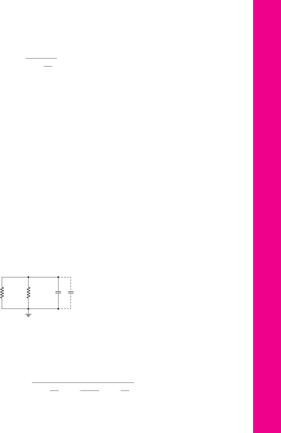
12.88 The equivalent circuit at the interface between the first and second stages of
an op-amp is shown in Figure P12.88. The parameters are
R
o1
= 2
M
,
R
i2
= 750
k
, and
C
i
= 1.2
pF. (a) Determine the pole frequency for this
part of the circuit. (b) Determine the additional Miller capacitance
C
M
that
would need to be added so that the pole frequency is moved to
f
PD
= 6
Hz.
(c) If the gain of the second-stage amplifier is 1000, what is the required
value of a feedback capacitor around the second-stage amplifier to produce
this Miller capacitance.
Chapter 12 Feedback and Stability 945
R
o1
R
i2
C
i
C
M
Figure P12.88
12.89 The amplifier described in Problem 12.82 is to be stabilized by moving the
first pole by using Miller compensation. Assuming that
f
P2
and
f
P3
remain
fixed, determine the frequency to which
f
P1
must be moved such that the
phase margin is 60 degrees.
12.90 The loop gain of an amplifier is given by
T ( f ) =
β
5 × 10
5
1 + j
f
10
4
1 + j
f
5 × 10
5
1 + j
f
10
7
nea80644_ch12_851-946.qxd 6/23/09 1:45 PM Page 945 pmath DATA-DISK:Desktop Folder:23/06/09:MHDQ134-12:

The pole at
f
P1
= 10
4
is to be moved such that the feedback amplifier
with a closed-loop low-frequency gain of 40 has a phase margin of 60 de-
grees. (a) Find the value of
β
. (b) Determine the new pole frequency.
COMPUTER SIMULATION PROBLEMS
Consider the circuit shown in Figure 12.24(a). Replace the input signal
source with an ideal signal voltage source. Using a computer simulation,
investigate the small-signal voltage gain, input resistance
R
if
, and output
resistance
R
of
as a function of the feedback resistance
R
F
.
12.92 For the circuit shown in Figure 12.39, investigate the small-signal voltage
gain, input resistance, and output resistance as a function of the transistor
width-to-length ratio, using a computer simulation.
12.93 Consider the circuit shown in Figure 12.37(a). Using a computer simula-
tion, plot the loop gain as a function of frequency.
12.94 In the circuit shown in Figure P12.42, use a computer simulation to plot
the small-signal voltage gain versus frequency. Determine the low-fre-
quency and high-frequency cutoff values.
DESIGN PROBLEMS
[Note: Each design should be correlated with a computer simulation analysis.]
*D12.95 The circuit shown in Figure P12.46 is to have a minimum loop gain of
T = 200
. Design the width-to-length ratios of the transistors to meet this
requirement. Use appropriate transistor parameters.
*D12.96 Op-amps with low-frequency open-loop gains of
5 × 10
4
and dominant-
pole frequencies of 8 Hz are available. Design a cascade of noninverting
amplifiers such that the overall voltage gain is 500 and the bandwidth is
15 kHz
*D12.97 An op-amp has a low-frequency open-loop gain of
5 × 10
4
and a dominant-
pole frequency of 10 Hz. Using this op-amp, design a preamplifier system
that can amplify the output of a microphone and produce a 1 V peak sig-
nal over a frequency range from 10 Hz to 15 kHz. The equivalent circuit
of the microphone is a voltage source in series with an output resistance.
The voltage source produces a 5 mV peak signal and the output resistance
is
10 k
.
*D12.98 The equivalent circuit of a transducer that measures the speed of a motor
is a current source in parallel with an output resistance. The current source
produces an output of
1 μA
per revolution per second of the motor and the
output resistance is
50 k
. Design a discrete transistor circuit that pro-
duces a full-scale output of 5 V for a maximum motor speed of 60 revolu-
tions per second. The nominal transistor current gain is
h
FE
= 100
with
tolerances of
±20
percent. The accuracy of the output signal is to remain
within
±1
percent.
946 Part 2 Analog Electronics
nea80644_ch12_851-946.qxd 6/23/09 1:45 PM Page 946 pmath DATA-DISK:Desktop Folder:23/06/09:MHDQ134-12:
12.91

Chapter
947
Operational
Amplifier Circuits
13
13
Thus far, we have considered basic circuit configurations, such as the common emitter,
emitter follower, and diff-amp, among others. We have discussed the basic concepts in
design and analysis, including biasing techniques, frequency response, and feedback
effects. In this chapter, we combine basic circuit configurations to form larger analog
circuits that are fabricated as integrated circuits. Operational amplifiers are used
extensively in electronic systems, so we concentrate on several configurations of
operational amplifier circuits.
We introduced the ideal op-amp in Chapter 9. Now, we analyze and design the
circuitry of the op-amp, to determine how the various circuit configurations can be
combined to form a nearly ideal op-amp.
PREVIEW
In this chapter, we will:
• Discuss the general design philosophy of an operational amplifier circuit.
• Describe and analyze the dc and ac characteristics of the classic 741 bipolar
operational amplifier circuit.
• Describe and analyze the dc and ac characteristics of CMOS operational
amplifier circuits.
• Describe and analyze the dc and ac characteristics of BiCMOS operational
amplifier circuits.
• Describe the characteristics of two hybrid JFET operational amplifier circuits.
• As an application, design a two-stage CMOS op-amp to match a given output
stage.
nea80644_ch13_947-1008.qxd 6/25/09 10:51 AM Page 947 VK TEMPWORK:Desktop Folder:25/06/09pp:MHDQ134-13: