Neamen D. Microelectronics: Circuit Analysis and Design
Подождите немного. Документ загружается.

948 Part 2 Analog Electronics
13.1 GENERAL OP-AMP CIRCUIT DESIGN
Objective: • Discuss the general design philosophy of an operational
amplifier circuit.
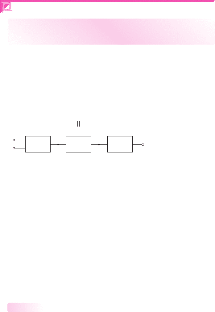
An operational amplifier, in general, is a three-stage circuit, as shown in Figure 13.1,
and is fabricated as an integrated circuit. The first stage is a differential amplifier,
the second stage provides additional voltage gain, and the third stage provides cur-
rent gain and low output impedance. A feedback capacitor is often included in the
second stage to provide frequency compensation as discussed in the last chapter. In
some cases, in particular with MOSFET op-amp circuits, only the first two stages
are used.
Diff–amp
Gain
stage
Output
stage
v
1
v
o
v
2
C
F
Figure 13.1 General block diagram of an operational amplifier
We have on numerous occasions made reference to the op-amp. In Chapter 9,
we analyzed and designed op-amp circuits using the ideal op-amp model. In
Chapter 10, we introduced current-source biasing and introduced the active load.
The differential amplifier, using current source biasing and active loads was
considered in Chapter 11. We also introduced the bipolar Darlington pair in
Chapter 11, which is often used as a second gain stage. Previously, in Chapter 8,
we considered the class-AB output stage that is often used in operational ampli-
fier circuits. These individual building blocks will now be combined to form the
operational amplifier.
In Chapter 9, as mentioned, we analyzed and designed ideal op-amp circuits.
Practical operational amplifiers, as we will see in this chapter, exhibit characteristics
that deviate from the ideal characteristics. Once we have analyzed these practical
op-amp circuits and determined some of their nonideal properties, we will then con-
sider, in the next chapter, the effect of these nonideal characteristics on the op-amp
circuits.
General Design Philosophy
All stages of the operational amplifier circuit are direct coupled. There are no cou-
pling capacitors and there are also no bypass capacitors. These types of capacitors
would require extremely large areas on the IC chip and hence are impractical. In ad-
dition, resistors whose values are over approximately
50 k
are avoided in ICs, since
they also require large areas and introduce parasitic effects. Op-amp circuits are de-
signed with transistors having matching characteristics.
13.1.1
nea80644_ch13_947-1008.qxd 6/23/09 1:59 PM Page 948 pmath DATA-DISK:Desktop Folder:23/06/09:MHDQ134-13:
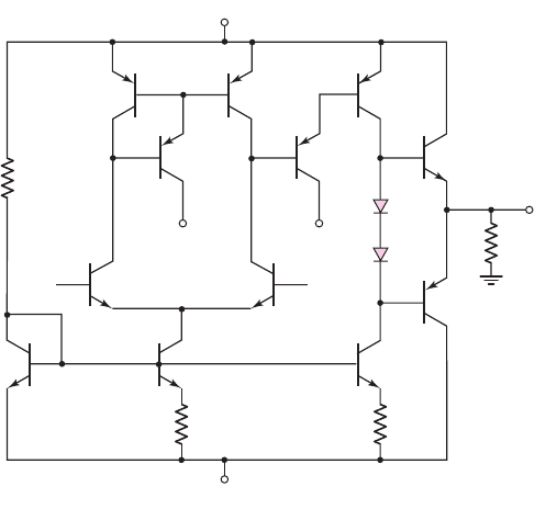
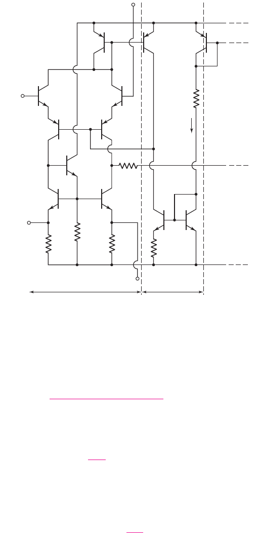
We may begin to design a simple bipolar operational amplifier by using the
knowledge gained in the previous chapters. Figure 13.2 shows the general configu-
ration of the circuit. The first stage will be a differential pair, Q
1
and Q
2
, biased with
a Widlar current source, Q
3
, Q
4
, and R
2
, and using a three-transistor active load.
Assuming matched transistors, we expect the dc voltage at the collector of Q
6
to be
two base-emitter voltage drops below the positive bias voltage. Therefore, the
Darlington pair, Q
8
and Q
9
, that forms the second stage should be properly biased.
The bias current for Q
8
is supplied by the Widlar current source, Q
4
, Q
10
, and R
3
. The
output stage is the complementary push–pull, emitter-follower configuration of Q
11
and Q
12
. The crossover distortion is eliminated by including the diodes D
1
and D
2
.
The emitter-follower configuration provides low output resistance so that the op-amp
can drive a load with minimal loading effect. By changing the value of R
3
slightly,
the current through Q
10
and Q
8
can be changed, which will change the collector–
emitter voltages across these transistors. This part of the circuit then acts as a dc
voltage shifter such that the output voltage,
v
O
, can be set equal to zero for zero
input voltages.
From results that we have derived previously, we expect the differential-mode
voltage gain of the first stage to be in the range of 10
2
–10
3
, depending on the specific
transistor parameters and the voltage gain of the second stage to also be the range of
10
2
–10
3
. The voltage gain of the output stage, an emitter follower, is essentially
unity. The overall voltage gain of the op-amp circuit is then expected to be in the
range of 10
4
–10
6
. From our study in Chapter 9, this magnitude of voltage gain is
required for the circuit to act essentially as an ideal op-amp.
The same op-amp configuration can be designed with MOS transistors. In
general, as we have seen, BJT circuits have higher voltage gains, whereas MOSFET
circuits have higher input resistances. So, whether a bipolar or MOSFET design is
used depends to a large extent on the specific application of the op-amp.
Chapter 13 Operational Amplifier Circuits 949
R
1
D
1
D
2
R
L
R
3
R
2
Q
5
Q
1
Q
2
v
2
v
O
v
1
Q
6
Q
8
Q
9
Q
11
V
+
V
–
V
–
V
–
Q
7
Q
4
Q
10
Q
12
Q
3
Figure 13.2 A simple bipolar operational amplifier
nea80644_ch13_947-1008.qxd 6/23/09 1:59 PM Page 949 pmath DATA-DISK:Desktop Folder:23/06/09:MHDQ134-13:

Circuit Element Matching
Integrated circuit design is based directly on the ability to fabricate transistors on a
chip that have nearly identical characteristics. In the analysis of current mirrors in
Chapter 10 and differential amplifiers in Chapter 11, we assumed that transistors in a
given circuit were matched. Transistors are matched when they have identical
parameters. For bipolar transistors, the parameters are
I
S
,
β
, and
V
A
. Recall that
I
S
includes the electrical parameters of the semiconductor material as well as the cross-
sectional area (geometry) of the base-emitter junction. For NMOS transistors, the
parameters are
V
TN
, K
n
, and
λ
n
, and for PMOS transistors, the same corresponding
parameters must be identical. Again, recall that the parameter K
n
contains semicon-
ductor parameters as well as the width-to-length (geometry) of the transistor.
The absolute parameter values of transistors on an IC chip may vary substan-
tially (on the order of
±25
percent) from one IC chip to the next because of process-
ing variations. However, the variation in parameter values of adjacent or nearby
transistors on a given IC chip are usually within a fraction of a percent. In general,
much of an amplifier design is based on the ratio of transistor parameters and on the
ratio of resistor values rather than on the absolute values. For this reason, the opera-
tional amplifiers described in this chapter can be fabricated as ICs, but are almost
impossible to fabricate with discrete circuit elements.
Test Your Understanding
TYU 13.1 Using a computer simulation, determine the dc voltages and currents in
the bipolar op-amp circuit in Figure 13.2. Use reasonable resistor values. Adjust the
value of R
3
such that the output voltage is nearly zero for zero input voltages.
TYU 13.2 Consider the basic diff-amp with active load and current biasing in Fig-
ure 13.2. Using a computer simulation, investigate the change in the voltage at the
collector of Q
2
as Q
1
and Q
2
, and also Q
5
and Q
6
, become slightly mismatched.
13.2 A BIPOLAR OPERATIONAL AMPLIFIER CIRCUIT
Objective: • Describe and analyze the dc and ac characteristics of
the classic 741 bipolar operational amplifier circuit.
The 741 op-amp has been produced since 1966 by many semiconductor device
manufacturers. Since then, there have been many advances in op-amp design, but the
741 is still a widely used general-purpose op-amp. Even though the 741 is a fairly old
design, it still provides a useful case study to describe the general circuit configura-
tion and to perform a detailed dc and small-signal analysis. From the ac analysis, we
determine the voltage gain and the frequency response of this circuit.
Circuit Description
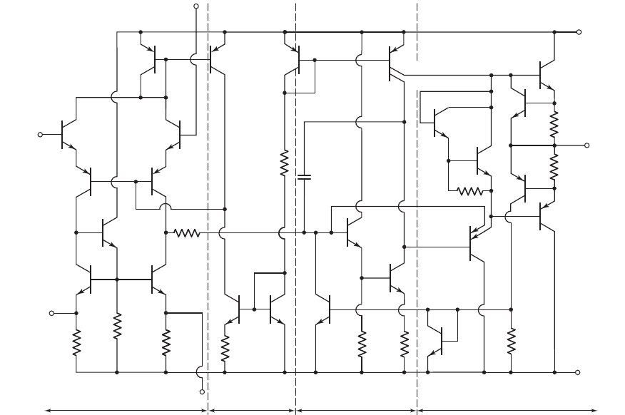
Figure 13.3 shows the equivalent circuit of the 741 op-amp. For easier analysis, we break
the overall circuit down into its basic circuits and consider each one individually.
13.2.1
13.1.2
950 Part 2 Analog Electronics
nea80644_ch13_947-1008.qxd 6/23/09 1:59 PM Page 950 pmath DATA-DISK:Desktop Folder:23/06/09:MHDQ134-13:
Chapter 13 Operational Amplifier Circuits 951
R
2
=
1 kΩ
R
3
=
50 kΩ
R
1
=
1 kΩ
V
–
V
+
R
11
=
50 kΩ
R
6
=
27 Ω
R
5
=
40 kΩ
C
1
=
30 pF
300 Ω
Q
22
Q
5
Q
1
Q
2
Q
14
Q
19
R
7
=
22 Ω
R
10
=
Q
3
Q
13A
Q
18
Q
20
Q
8
Q
24
Q
11
R
9
=
50 kΩ
R
4
=
5 kΩ
Q
10
Q
23
Q
16
Q
15
Q
21
Q
12
Q
9
Q
17
Q
13B
R
8
=
100 Ω
50 kΩ
Q
7
Q
6
Q
4
Offset
null
Inverting
input
Output
Offset
null
Noninverting
input
Input stage Bias circuit Gain stage Output stage
Figure 13.3 Equivalent circuit, 741 op-amp
As with most op-amps, this circuit consists of three stages: the input differential
amplifier, the gain stage, and the output stage. Figure 13.3 also shows a separate bias
circuit, which establishes the bias currents throughout the op-amp. Like most op-
amps, the 741 is biased with both positive and negative supply voltages. This elimi-
nates the need for input coupling capacitors, which in turn means that the circuit is
also a dc amplifier. The dc output voltage is zero when the applied differential input
signal is zero. Typical supply voltages are
V
+
= 15
V and
V
−
=−15 V
, although
input voltages as low as
±5
V can be used.
Input Diff-Amp
The input diff-amp stage is more complex than those previously covered. The input
stage consists of transistors Q
1
through Q
7
, with biasing established by transistors Q
8
through Q
12
. The two input transistors Q
1
and Q
2
act as emitter followers, which
results in a high differential input resistance. The differential output currents from Q
1
and Q
2
are the inputs to the common-base amplifier formed by Q
3
and Q
4
, which
provides a relatively large voltage gain.
Transistors Q
5
, Q
6
, and Q
7
, with associated resistors R
1
, R
2
, and R
3
, form the
active load for the diff-amp. A single-sided output at the common collectors of Q
4
and Q
6
is the input signal to the following gain stage.
The dc output voltage at the collector of Q
6
is at a lower potential than the inputs
at the bases of Q
1
and Q
2
. As the signal passes through the op-amp, the dc voltage
level shifts several times. By design, when the signal reaches the output terminal, the
nea80644_ch13_947-1008.qxd 6/23/09 1:59 PM Page 951 pmath DATA-DISK:Desktop Folder:23/06/09:MHDQ134-13:
dc voltage should be zero if a zero differential input signal is applied. The two null
terminals on the input stage are used to make appropriate adjustments to accomplish
this design goal. The “null technique” and the corresponding portion of the circuit
will be discussed in detail in the next chapter.
The dc current biasing is initiated through the diode-connected transistors Q
12
and Q
11
and resistor R
5
. Transistors Q
11
and Q
10
, with resistor R
4
, form a Widlar
current source that establishes the bias currents in the common-base transistors Q
3
and Q
4
, as well as the current mirror formed by Q
9
and Q
8
.
Transistors Q
3
and Q
4
are lateral pnp devices, which refers to the fabrication
process and the geometry of the transistors. Lateral pnp transistors provide added
protection against voltage breakdown, although the current gain is smaller than in
npn devices.
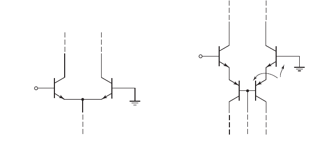
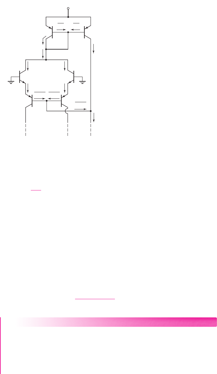
Figure 13.4(a) shows a basic common-emitter differential pair used as the input
to a diff-amp. If the input voltage V
1
were to be connected to a supply voltage of
15 V, with V
2
at ground potential, then the B–E junction of Q
2
would be reverse bi-
ased by approximately 14.3 V. Since the breakdown voltage of an npn B–E junction
is typically in the range of 3–6 V, transistor Q
2
in Figure 13.4(a) would probably
enter breakdown and suffer permanent damage.
952 Part 2 Analog Electronics
+
+
–
–
Q
1
Q
2
+
+
–
Q
1
Q
2
+
–
–
Q
3
Q
4
(a) (b)
≈ 0.7 V ≈ 14.3 V
V
1
= 15 V
V
2
≈ 0.7 V
≈ 0.7 V
≅ 13.6 V
V
1
= 15 V
V
2
Figure 13.4 (a) Basic common-emitter differential pair, with a large differential voltage and
(b) the 741 input stage, with a large differential voltage
By comparison, Figure 13.4(b) shows the input stage of the 741 op-amp with the
same input voltages. The B–E junctions of Q
1
and Q
3
are forward biased, which means
that the series combination of B–E junctions of Q
2
and Q
4
is reverse biased by approx-
imately 13.6 V. The breakdown voltage of a lateral pnp B–E junction is typically on the
order of 50 V, which means that for this input voltage polarity, the B–E junction of Q
4
provides the necessary breakdown protection for the input diff-amp stage.
Gain Stage
The second, or gain, stage consists of transistors Q
16
and Q
17
. Transistor Q
16
operates
as an emitter follower; therefore, the input resistance of the gain stage is large. As
previously discussed, a large input resistance to the gain stage minimizes loading
effects on the diff-amp stage.
Transistor Q
13
is effectively two transistors connected in parallel, with common
base and emitter terminals. The area of Q
13A
is effectively one-fourth the area of Q
12
,
nea80644_ch13_947-1008.qxd 6/23/09 1:59 PM Page 952 pmath DATA-DISK:Desktop Folder:23/06/09:MHDQ134-13:

and the area of Q
13B
is effectively three-fourths that of Q
12
. Transistor Q
13B
provides
the bias current for Q
17
and also acts as an active load to produce a high-voltage gain.
Transistor Q
17
operates in a common-emitter configuration; therefore, the voltage at
the collector of Q
17
is the input signal to the output stage. The signal undergoes
another dc level shift as it goes through this gain stage.
The 741 is internally compensated by the feedback capacitor C
1
connected
between the output and input terminals of the gain stage. This Miller compensation
technique assures that the 741 op-amp forms stable feedback circuits.
Output Stage
The output stage of an op-amp should provide a low output resistance, as well as a
current gain, if it is to drive relatively large load currents. The output stage is there-
fore a class-AB circuit consisting of the complementary emitter-follower pair Q
14
and Q
20
.
The output of the gain stage is connected to the base of Q
22
, which operates as
an emitter follower and provides a very high input resistance; the gain stage therefore
suffers no significant loading effects due to the output stage. Transistor Q
13A
provides
a bias current for Q
22
, as well as for Q
18
and Q
19
, which are used to establish a qui-
escent bias current in the output transistors Q
14
and Q
20
. Transistors Q
15
and Q
21
are
referred to as short-circuit protection devices. These transistors are normally off;
they conduct only if the output is inadvertently connected to ground, resulting in a
very large output current. We will consider the characteristics of the output stage in
Section 13.2.2.
An abbreviated data sheet for the 741 is shown in Table 13.1. During our
discussions in this chapter, we will compare our analysis results to the values in the
table. A more complete data sheet for the 741 op-amp is given in Appendix B.
Chapter 13 Operational Amplifier Circuits 953
Table 13.1 Data for 741 at T
=
300 K and supply voltage of
±
15 V
Parameter Minimum Typical Maximum Units
Input bias current 80 500 nA
Differential-mode input
resistance 0.3 2.0
M
Input capacitance 1.4 pF
Output short-circuit current 25 mA
Open-loop gain (
R
L
≥ 2k
) 50,000 200,000 V/V
Output resistance 75
Unity-gain frequency 1 MHz
DC Analysis
In this section, we will analyze the dc characteristics of the 741 op-amp to determine
the dc bias currents. We assume that both the noninverting and inverting input termi-
nals are at ground potential, and that the dc supply voltages are
V
+
= 15 V
and
V
−
=−15 V
. As an approximation, we assume
V
BE
= 0.6V
for npn transistors and
V
EB
= 0.6V
for pnp transistors. In most dc calculations, we neglect dc base
currents, although we include base current effects in a few specific cases.
13.2.2
nea80644_ch13_947-1008.qxd 6/25/09 10:04 AM Page 953 pmath DATA-DISK:Desktop Folder:25/06/09:MHDQ134-13:
Bias Circuit and Input Stage
Figure 13.5 shows the bias circuit and input stage portion of the 741 circuit. The
reference current, which is established in the bias circuit branch composed of Q
12
,
Q
11
, and R
5
, is
I
REF
=
V
+
− V
EB12
− V
BE11
− V
−
R
5
(13.1)
Transistors Q
11
and Q
10
and resistor R
4
form a Widlar current source. Therefore, I
C10
is determined from the relationship
I
C10
R
4
= V
T
ln
I
REF
I
C10
(13.2)
where V
T
is the thermal voltage and Q
10
and Q
11
are assumed to be matched transistors.
Neglecting base currents,
I
C8
= I
C9
= I
C10
. The quiescent collector currents in
Q
1
through Q
4
are then
I
C1
= I
C2
= I
C3
= I
C4
=
I
C10
2
(13.3)
Assuming the dc currents in the input stage are exactly balanced, the dc voltage at the
collector of Q
6
, which is the input to the second stage, is the same as the dc voltage
at the collector of Q
5
. We can write
V
C6
= V
BE7
+ V
BE6
+ I
C6
R
2
+ V
−
(13.4)
As previously discussed, the dc level shifts through the op-amp.
954 Part 2 Analog Electronics
R
2
=
1 kΩ
R
3
=
50 kΩ
R
1
=
1 kΩ
Offset
null
Inverting
input
Offset
null
Noninverting
input
V
–
V
+
R
5
=
40 kΩ
300 Ω
Q
5
Q
6
Input stage Bias circuit
Q
1
Q
2
Q
3
Q
4
Q
8
Q
9
Q
7
R
4
=
5 kΩ
Q
10
Q
11
Q
12
I
REF
Figure 13.5 Bias circuit and input stage portion of 741 op-amp circuit
nea80644_ch13_947-1008.qxd 6/23/09 1:59 PM Page 954 pmath DATA-DISK:Desktop Folder:23/06/09:MHDQ134-13:

EXAMPLE 13.1
Objective: Calculate the dc currents in the bias circuit and input stage of the
741 op-amp.
The bias circuit and input stage are shown in Figure 13.5.
Solution: From Equation (13.1), the reference current is
I
REF
=
V
+
− V
EB12
− V
BE11
− V
−
R
5
=
15 − 0.6 −0.6 −(−15)
40
= 0.72 mA
Current I
C10
is found from Equation (13.2), as follows:
I
C10
(5) = (0.026) ln
0.72
I
C10
By trial and error, we find that
I
C10
= 19 μA
. The bias currents in the input stage
are then
I
C1
= I
C2
= I
C3
= I
C4
= 9.5 μA
From Equation (13.4), the voltage at the collector of Q
6
is
V
C6
= V
BE7
+ V
BE6
+ I
C6
R
2
+ V
−
= 0.6 +0.6 +(0.0095)(1) + (−15)
or
V
C6
∼
=
−13.8V
Comment: The bias currents in the input stage are quite small; the input base
currents at the noninverting and inverting terminals are generally in the nanoampere
range. Small bias currents mean that the differential input resistance is large.
EXERCISE PROBLEM
Ex 13.1: Consider the input stage and bias circuit of the 741 op-amp shown in
Figure 13.5. The resistor
R
5
is changed to
R
5
= 25 k
, and the bias voltages
are
V
+
= 5
V and
V
−
=−5
V. Let
V
BE
(on) = V
EB
(on) = 0.6
V and neglect
base currents. Determine the currents
I
REF
,
I
C10
,
I
C1
, and
I
C2
. (Ans.
I
REF
=
0.352 mA, I
C10
= 16 μA, I
C1
= I
C2
= 8 μ
A)
The transistor current gain of the lateral pnp transistors Q
3
, Q
4
, Q
8
, and Q
9
may
be relatively small, which means that the base currents in these transistors may not
be negligible. To determine the effect of the base currents, consider the expanded
input stage shown in Figure 13.6. The base currents in the npn transistors are still
assumed to be negligible. Current I
C10
establishes the base currents in Q
3
and Q
4
,
which then establish the emitter currents designated as I. At the Q
8
collector,
we have
2I = I
C8
+
2I
C9
β
p
= I
C9
1 +
2
β
p
(13.5)
Since Q
8
and Q
9
are matched,
I
C8
= I
C9
. Then,
I
C10
=
2I
1 + β
p
+ I
C9
=
2I
1 + β
p
+
2I
1 +
2
β
p
= 2I
β
2
p
+2β
p
+2
β
2
p
+3β
p
+2
(13.6)
Chapter 13 Operational Amplifier Circuits 955
nea80644_ch13_947-1008.qxd 6/23/09 1:59 PM Page 955 pmath DATA-DISK:Desktop Folder:23/06/09:MHDQ134-13:
Even if the pnp transistor base currents are not negligible, the bias currents in Q
1
and
Q
2
are, from Equation (13.6), very nearly
I =
I
C10
2
(13.7)
This bias current is essentially the same as originally assumed in Equation (13.3).
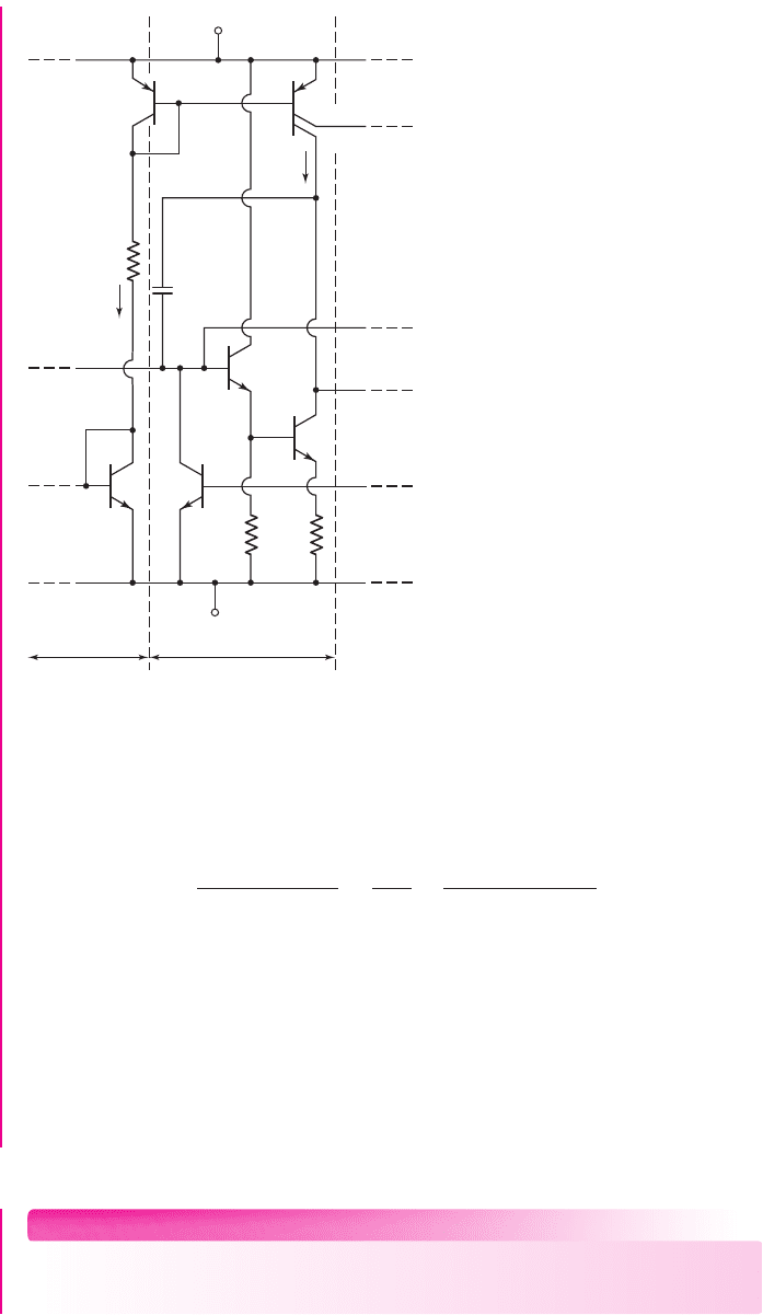
Gain Stage
Figure 13.7 shows the reference portion of the bias circuit and the gain stage. The
reference current is given by Equation (13.1). Transistors Q
12
and Q
13
form a current
mirror, and Q
13B
has a scale factor 0.75 times that of Q
12
. Neglecting base currents,
current I
C13B
is then
I
C13B
= 0.75I
REF
(13.8)
The emitter current in Q
16
is the sum of the base current in Q
17
and the current in R
9
,
as follows:
I
C16
∼
=
I
E16
= I
B17
+
I
E17
R
8
+ V
BE17
R
9
(13.9)
EXAMPLE 13.2
Objective: Calculate the bias currents in the gain stage of the 741 op-amp in Fig-
ure 13.7. Assume bias voltages of
±15
V.
Solution: In Example 13.1, we determined the reference current to be
I
REF
=
0.72
mA. From Equation (13.8), the collector current in Q
17
is
I
C17
= I
C13B
= 0.75I
REF
= (0.75)(0.72) = 0.54 mA
956 Part 2 Analog Electronics
Q
1
Q
2
V
+
Q
3
Q
4
Q
9
Q8
I
C9
I
C10
I
C8
2I
I
I
I
I
II
1 +
b
P
1 +
b
P
1 +
b
P
2I
I
C9
b
P
I
C9
b
P
Figure 13.6 Expanded input stage, 741 op-amp, showing base currents
nea80644_ch13_947-1008.qxd 6/23/09 1:59 PM Page 956 pmath DATA-DISK:Desktop Folder:23/06/09:MHDQ134-13:
Assuming
β = 200
for the npn transistor, the collector current in Q
16
is, from Equa-
tion (13.9),
I
C16
∼
=
I
B17
+
I
E17
R
8
+ V
BE17
R
9
=
0.54
200
+
(0.54)(0.1) + 0.6
50
or
I
C16
= 15.8 μA
Comment: The small bias current in Q
16
, in conjunction with the resistor R
9
, ensures
that the input resistance to the gain stage is large, which minimizes loading effects on
the diff-amp stage. The small bias current in Q
16
also means that the base current in
Q
16
is negligible, as assumed in the dc analysis of the input stage.
EXERCISE PROBLEM
Ex 13.2: Repeat Example 13.2 for bias voltages of
±5
V. (Ans.
I
REF
= 0.22 mA
,
I
C17
= 0.165 mA
,
I
C16
= 13.2 μA
)
Chapter 13 Operational Amplifier Circuits 957
V
–
V
+
R
5
=
40 kΩ
C
1
=
30 pF
Bias circuit Gain stage
Q
13A
Q
11
Q
23
R
9
=
50 kΩ
Q
16
V
C6
Q
12
Q
17
Q
13B
R
8
=
100 Ω
I
REF
I
C13B
Figure 13.7 Reference circuit and gain stage, 741 op-amp
nea80644_ch13_947-1008.qxd 6/23/09 1:59 PM Page 957 pmath DATA-DISK:Desktop Folder:23/06/09:MHDQ134-13: