Neubauer A., Freudenberger J., Kuhn V. Coding theory: algorithms, architectures and applications
Подождите немного. Документ загружается.


266 SPACE–TIME CODES
where
X
= diag[λ
1
···λ
r
] is a diagonal matrix containing the different power levels.
The transmit filter V
X
comprises those columns of V
H
that correspond to the r largest
singular values of H. Equivalently, the receive filter U
X
contains those columns of U
H
that are associated with the used eigenmodes. Using V
X
and U
X
leads to
y = U
H
X
· r =
H
·
X
· s +
˜
n .
Since
H
and
X
are diagonal matrices, the data streams are perfectly separated into
parallel channels whose signal-to-noise ratios amount to
γ
i
= σ
2
H,i
· λ
i
·
σ
2
X
σ
2
N
= σ
2
H,i
· λ
i
·
E
s
N
0
.
They depend on the squared singular values σ
2
H,i
and the specific transmit power levels λ
i
.
For digital communications, the input alphabet is not Gaussian distributed as assumed in
Section 5.3 but consists of discrete symbols. Hence, finding the optimal bit and power allo-
cation is a combinatorial problem and cannot be found by gradient methods as discussed on
241. Instead, algorithms presented elsewhere (Fischer and Huber, 1996; Hughes-Hartogs,
1989; Krongold et al., 1999; Mutti and Dahlhaus, 2004) have to be used. Different opti-
misation strategies are possible. One target may be to maximise the throughput at a given
average error rate. Alternatively, we can minimise the error probability at a given total
throughput or minimise the transmit power for target error and data rates.
No Channel Knowledge at Transmitter
In Section 5.3 it was shown that the resource space can be used even in the absence of
channel knowledge at the transmitter. The loss compared with the optimal waterfilling
solution is rather small. However, the price to be paid is the application of advanced signal
processing tools at the receiver. A famous example is the Bell Labs Layered Space–Time
(BLAST) architecture (Foschini, 1996; Foschini and Gans, 1998; Foschini et al., 1999).
Since no channel knowledge is available at the transmitter, the best strategy is to transmit
independent equal power data streams called layers. At least two BLAST versions exist.
The first, termed diagonal BLAST, distributes the data streams onto the transmit antennas
according to a certain permutation pattern. This kind of interleaving ensures that the symbols
within each layer experience more different fading coefficients, leading to a higher diversity
gain during the decoding process.
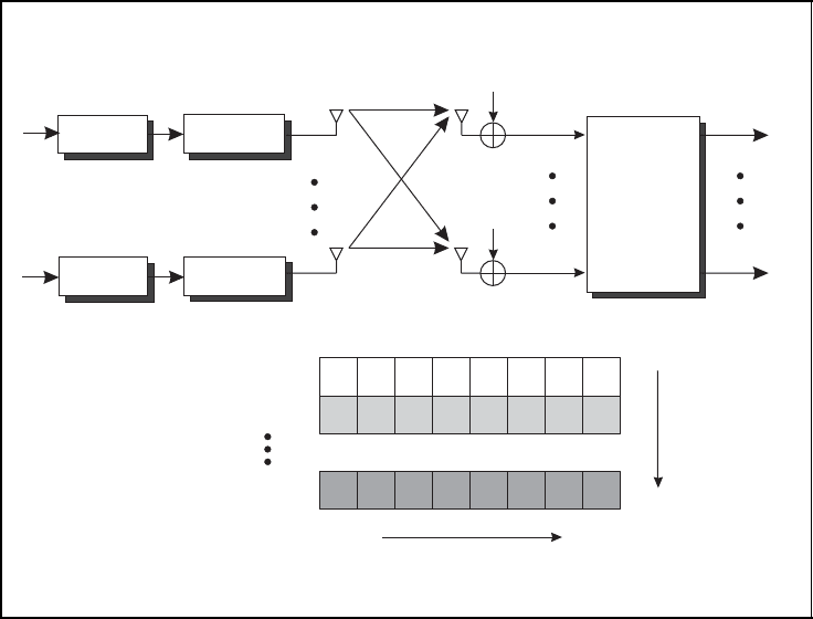
In this section, we focus only on the second version, termed vertical BLAST, which is
shown in Figure 5.39. Hence, no interleaving between layers is performed and each data
stream is solely assigned to a single antenna, leading to x = s. The name stems from the
vertical arrangement of the layers. This means that channel coding is applied per layer.
Alternatively, it is also possible to distribute a single coded data stream onto the transmit
antennas. There are slight differences between the two approaches, especially concerning
the detection at the receiver. As we will soon see, per-layer encoding makes it possible to
include the decoder in an iterative turbo detection, while this is not directly possible for a
single code stream.
From the mathematical description in Equation (5.78) we see that a superposition
r
µ
=
N
T
ν=1
h
µ,ν
· x
ν
+ n
µ
SPACE–TIME CODES 267
Spatial multiplexing with V-BLAST
V-BLAST
space-time
u
1
u
N
T
b
1
b
N
T
˜x
1
˜x
N
T
h
1,1
h
1,N
T
h
N
R
,1
h
N
R
,N
T
x
1
x
1
x
2
x
N
T
x
N
T
n
1
n
N
R
r
1
r
N
R
time
space
encoder
encoder
modulator
modulator
detector
Figure 5.39: Multilayer transmission with vertical BLAST (V-BLAST) and per-layer
encoding
of all transmitted layers is obtained at each receive antenna 1 ≤ µ ≤ N
R
. The task of
the space –time detector is to separate the data streams again. In coded systems, the
space–time detector and decoder are generally implemented separately for complexity
reasons. However, both components can exchange iteratively information equivalent to
the turbo principle for concatenated codes discussed in Chapter 4. We will continue the
discussion with the optimum bit-by-bit space–time detector that delivers LLRs. Since the
computational complexity becomes demanding for high modulation levels and many layers,
alternative detection strategies are discussed subsequently.
5.5.2 Iterative APP Preprocessing and Per-layer Decoding
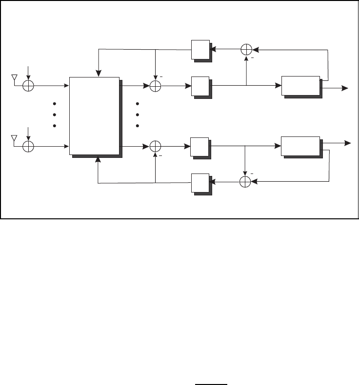
As mentioned above, we will now consider a receiver structure as depicted in Figure 5.40.
A joint preprocessor calculates LLRs L(
ˆ
b
ν
| r) for each layer ν on the basis of the received
samples r
1
up to r
N
R
. As we assume a memoryless channel H, the preprocessor can work
in a symbol-by-symbol manner without performance loss. After de-interleaving, the FEC
decoders deliver independently for each layer estimates ˆu
ν
of the information bits as well
as LLRs L(
ˆ
b
ν
) of the coded bits. From the LLRs, the extrinsic parts, i.e. the parts generated
268 SPACE–TIME CODES
Turbo detection for V-BLAST
L(b
1
| r)
L(b
N
T
| r)
ˆu
1
ˆu
N
T
L(b
1
)
L(b
N
T
)
L
a
(b
1
)
L
a
(b
N
T
)
n
1
n
N
R
r
1
r
N
R
APP
decoder
decoder
−1
−1
processor
Figure 5.40: Iterative turbo detection of V-BLAST for per-layer encoding
from the code’s redundancy, are extracted, interleaved and fed back as a-priori information
to the preprocessor. Now, a second iteration can start with an improved output of the joint
preprocessor owing to the available side information from the previous iteration. As already
described in Chapter 4, an iterative detection process is obtained that aims to approach the
maximum likelihood solution (Liew and Hanzo, 2002).
We will now have a more thorough look at the joint preprocessor. The major steps
are summarised in Figure 5.41. From Equation (5.79) we see that the LLR depends on the
ratio of conditional probabilities Pr{b
ν
= ξ | r} which are defined as
Pr{b
ν
= ξ | r}=
p(b
ν
, r)
p(r)
.
Since p(r) is identical in numerator and denominator of the log likelihood ratio, it can be
skipped, leading to the right-hand side of Equation (5.79). The joint probability densities
have to be further processed to obtain a tractable form. For multilevel modulation schemes
such as QAM and PSK, each symbol s is assigned to several bits b
ν
with 1 ≤ ν ≤ ld(M).
The probability that a certain bit b
ν
takes a value ξ can be calculated by summing the
probabilities Pr{s} over those symbols s whose νth bit equals ξ
Pr{b
ν
= ξ }=
s,bν=ξ
Pr{s}.
At this point it has to be emphasised that r comprises corrupted versions of all N
T
trans-
mitted symbols. Therefore, it is not sufficient to consider a single symbol s. Instead, the set

SPACE–TIME CODES 269
APP-preprocessor for V-BLAST
■ LLR of APP preprocessor
L(b
ν
| r) = log
Pr{b
ν
= 0 | r}
Pr{b
ν
= 1 | r}
= log
p(b
ν
= 0, r)
p(b
ν
= 1, r)
(5.79)
■ Joint probability density
p(b
ν
= ξ,r) =
s∈S
ν
(ξ)
p(s, r) =
s∈S
ν
(ξ)
p(r | s) · Pr{s} (5.80)
■ Conditional probability density function
p(r | s) ∝= exp
!
−
r − Hs
2
σ
2
N
"
(5.81)
■ A-priori probability
Pr{s}=
N
T
ld(M)
ν=1
Pr{b
ν
(s)} (5.82)
Figure 5.41: APP calculation steps for the joint preprocessor of V-BLAST systems
of N
T
symbols and, correspondingly, all bits b
ν
with 1 ≤ ν ≤ N
T
ld(M) have to be taken
into account. For this purpose, we define a kind of vector modulation that maps a vector
b =
b
1
b
2
··· b
N
T
ld(M)
T
of N
T
ld(M) bits onto a vector
s =
s
1
s
2
··· s
N
T
T
of N
T
symbols. The set of vectors is divided into subsets S
ν
(ξ) containing those symbol
ensembles for which the νth bit of their binary representation b takes the value b
ν
=
ξ, leading to Equation (5.80). This transforms the generally unknown joint probability
p(b
ν
, r) into an expression depending on the conditional densities p(r | s) and the a-priori
probabilities Pr{s}. The former determine the channel statistics and are proportional to the
expression in Equation (5.81). Assuming that all bits b
ν
are statistically independent, the
a-priori probability Pr{s} can be factorised into the marginal probabilities according to
Equation (5.82) where the bits b
ν
(s) are determined by the specific symbol vector s.
From the above equations we can already conclude that the computational complexity
grows linearly with the number of possible hypotheses and, hence, exponentially with the

270 SPACE–TIME CODES
number of layers as well as the number of bits per symbol. Thus, this optimal approach is
feasible only for small systems and small modulation alphabets.
Turbo Iterations
In the first iteration, no a-priori information from the decoders is available. Hence, the
a-priori probabilities are constant, Pr{s}=2
−N
T
ld(M)
, and can be dropped. The insertion
of Equation (5.80) and Equation (5.81) into Equation (5.79) then leads to Equation (5.83)
in Figure 5.42. We observe that the numerator and denominator only differ by the sub-
sets S
ν
(ξ) which distinguish the two hypotheses b
ν
= 0 and b
ν
= 1. Subsequent per-layer
soft-output decoding according to Bahl, Cocke, Jelinek, Raviv (BCJR) or max-log MAP
algorithms (rf. to Section 3.4) provides LLRs for each code bit and layer.
APP preprocessor and turbo iterations
■ LLR of APP preprocessor in first iteration
L(b
ν
| r) = log
#
s∈S
ν
(0)
exp
!
−
r−Hs
2
σ
2
N
"
#
s∈S
ν
(1)
exp
!
−
r−Hs
2
σ
2
N
"
(5.83)
■ Calculating a-priori probabilities from decoder LLRs
Pr{b
ν
= ξ }=
exp[−ξL
a
(b
ν
)]
1 + exp[−L
a
(b
ν
)]
(5.84)
■ A-priori information per symbol
Pr{s}=
N
T
ld(M)
ν=1
exp[−b
ν
(s)L
a
(b
ν
)]
1 + exp[−L
a
(b
ν
)]
→
N
T
ld(M)
ν=1
exp[−b
ν
(s)L
a
(b
ν
)] (5.85)
■ LLR of APP preprocessor after first iteration
L(b
ν
| r) = log
#
s∈S
ν
(0)
exp
!
−
r−Hs
2
σ
2
N
−
#
N
T
ld(M)
ν=1
b
ν
(s)L
a
(b
ν
)
"
#
s∈S
ν
(1)
exp
!
−
r−Hs
2
σ
2
N
−
#
N
T
ld(M)
ν=1
b
ν
(s)L
a
(b
ν
)
"
(5.86)
Figure 5.42: APP preprocessor and turbo iterations for the V-BLAST system

SPACE–TIME CODES 271
They are fed back into the APP processor and have to be converted into a-priori proba-
bilities Pr{s}. Using the results from the introduction of APP decoding given in Section 3.4,
we can easily derive Equation (5.83) where ξ ∈{0, 1} holds. Inserting the expression for
the bit-wise a-priori probability in Equation (5.84) into Equation (5.82) directly leads to
Equation (5.85). Since the denominator of Equation (5.84) does not depend on the value
of b
ν
itself but only on the decoder output L(b
ν
), it is independent of the specific symbol
vector s represented by the bits b
ν
. Hence, it becomes a constant factor regarding s and
can be dropped, as done on the right-hand side.
Replacing the a-priori probabilities in Equation (5.79) with the last intermediate results
leads to the final expression in Equation (5.86). On account of b
ν
∈{0, 1}, the a-priori
LLRs only contribute to the entire result if a symbol vector s with b
ν
= 1 is considered.
For these cases, the L(b
ν
) contains the correct information only if it is negative, otherwise
its information is wrong. Therefore, true a-priori information increases the exponents in
Equation (5.86) which is consistent with the negative squared Euclidean distance which
should also be maximised.
Max-Log MAP Solution
As already mentioned above, the complexity of the joint preprocessor still grows expo-
nentially with the number of users and the number of bits per symbol. In Section 3.4 a
suboptimum derivation of the BCJR algorithm has been introduced. This max-log MAP
approach works in the logarithmic domain and uses the Jacobian logarithm
log
e
x
1
+ e
x
2
= log
.
e
max{x
1
,x
2
}
1 + e
−|x
1
−x
2
|
/
= max{x
1
,x
2
}+log
.
1 + e
−|x
1
−x
2
|
/
Obviously, the right-hand side depends on the maximum of x
1
and x
2
as well as on the
absolute difference. If the latter is large, the logarithm is close to zero and can be dropped.
We obtain the approximation
log
e
x
1
+ e
x
2
≈ max{x
1
,x
2
} (5.87)
Applying approximation (5.87) to Equation (5.86) leads to
L(b
ν
| r) ≈ min
s∈S
ν
(1)
r − Hs
2
σ
2
N
+
N
T
ld(M)
ν=1
b
ν
(s)L
a
(b
ν
)
,
− min
s∈S
ν
(0)
r − Hs
2
σ
2
N
+
N
T
ld(M)
ν=1
b
ν
(s)L
a
(b
ν
)
,
(5.88)
We observe that the ratio has become a difference and the sums in numerator and denom-
inator have been exchanged by the minima searches. The latter can be performed pairwise
between the old minimum and the new hypothesis. It has to be mentioned that the first
minimisation runs over all s ∈ S
ν
(0), while the second uses s ∈ S
ν
(1).
272 SPACE–TIME CODES
Using Expected Symbols as A-Priori Information
Although the above approximation slightly reduces the computational costs, often they
may be still too high. The prohibitive complexity stems from the sum over all possible
hypotheses, i.e. symbol vectors s. A further reduction can be obtained by replacing the
explicit consideration of each hypothesis with an average symbol vector
¯
s. To be more
precise, the sum in Equation (5.86) is restricted to the M hypotheses of a single symbol
s
µ
in s containing the processed bit b
ν
. This reduces the number of hypotheses markealy
from M
N
T
to M. For the remaining N
T
− 1 symbols in s, their expected values
¯s
µ
=
ξ∈S
ξ · Pr{ξ }∝
ξ∈S
ξ ·
ld(M)
ν=1
e
−b
ν
(ξ)L
a
(b
ν
)
(5.89)
are used. They are obtained from the a-priori information of the FEC decoders. As already
mentioned before, the bits b
ν
are always associated with the current symbol ξ of the sum.
In the first iteration, no a-priori information from the decoders is available, so that no
expectation can be determined. Assuming that all symbols are equally likely would result
in ¯s
µ
≡ 0 for all µ. Hence, the influence of interfering symbols is not considered at all
and the tentative result after the first iteration can be considered to be very bad. In many
cases, convergence of the entire iterative process cannot be achieved. Instead, either the
full-complexity algorithm or alternatives that will be introduced in the next subsections
have to be used in this first iteration.
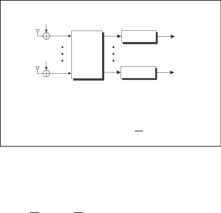
5.5.3 Linear Multilayer Detection
A reduction in the computational complexity can be achieved by separating the layers
with a linear filter. These techniques are already well known from multiuser detection
strategies in CDMA systems (Honig and Tsatsanis, 2000; Moshavi, 1996). In contrast to
optimum maximum likelihood detectors, linear approaches do not search for a solution in
the finite signal alphabet but assume continuously distributed signals. This simplifies the
combinatorial problem to an optimisation task that can be solved by gradient methods.
This leads to a polynomial complexity with respect to the number of layers instead of an
exponential dependency. Since channel coding and linear detectors can be treated separately,
this section considers an uncoded system. The MIMO channel output can be expressed by
the linear equation system
r = Hs + n
which has to be solved with respect to s.
Zero-Forcing Solution
The zero-forcing filter totally suppresses the interfering signals in each layer. It delivers the
vector s
ZF
∈ C
N
T
which minimises the squared Euclidean distance to the received vector r
s
ZF
= argmin
˜
s∈C
N
T
4
4
r − H
˜
s
4
4
2
(5.90)
Although Equation (5.90) resembles the maximum likelihood approach, it significantly dif-
fers from it by the unconstraint search space C
N
T
instead of S
N
T
. Hence, the result s
ZF
is
SPACE–TIME CODES 273
Linear detection for the V-BLAST system
linear
ZF/MMSE
detector
demodulator
demodulator
n
1
n
N
R
r
1
r
N
R
˜s
1
˜s
N
T
ˆ
u
1
ˆ
u
N
T
■ zero-forcing filter
W
ZF
= H ·
H
H
H
−1
■ Minimum mean-squared error filter
W
MMSE
= H ·
H
H
H +
σ
2
N
σ
2
S
I
N
T
−1
Figure 5.43: Linear detection for the V-BLAST system
generally not an element of S
N
T
. However, this generalisation transforms the combinatorial
problem into one that can be solved by gradient methods. Hence, the squared Euclidean dis-
tance in Equation (5.90) is partially differentiated with respect to
˜
s
H
. Setting this derivative
to zero
∂
∂
˜
s
H
4
4
r − H
˜
s
4
4
2
=
∂
∂
˜
s
H
r − H
˜
s
H
·
r − H
˜
s
=−H
H
r + H
H
H
˜
s
!
= 0 (5.91)
yields the solution
s
ZF
= W
H
ZF
· r = H
†
· r =
H
H
H
−1
· H
H
· r (5.92)
The filter matrix W
ZF
= H
†
= H
H
H
H
−1
is called the Moore–Penrose, or pseudo, inverse
and can be expressed by the right-hand side of Equation (5.92) if H has full rank. In this
case, the inverse of H
H
H exists and the filter output becomes
s
ZF
= (H
H
H)
−1
H
H
·
Hs + n
= s + W
H
ZF
· n (5.93)
Since the desired data vector s is only disturbed by noise, the final detection is obtained by
a scalar demodulator s
ZF
= Q(s
ZF
) of the filter outputs s
ZF
. The non-linear function Q(·)
represents the hard-decision demodulation.
Although the filter output does not suffer from interference, the resulting signal-to-noise
ratios per layer may vary significantly. This effect can be explained by the fact that the
total suppression of interfering signals is achieved by projecting the received vector into
the null space of all interferers. Since the desired signal may have only a small component

274 SPACE–TIME CODES
lying in this subspace, the resulting signal-to-noise ratio is low. It can be expressed by the
error covariance matrix
ZF
= E
s
ZF
− s
s
ZF
− s
H
= E
s + W
H
ZF
n − s
s + W
H
ZF
n − s
H
= W
H
ZF
E
nn
H
W
ZF
= σ
2
N
W
H
ZF
W
ZF
= σ
2
N
H
H
H
−1
(5.94)
which contains on its diagonal the mean-squared error for each layer. The last row holds if
the covariance matrix of the noise equals a diagonal matrix containing the noise power σ
2
N
.
The main drawback of the zero-forcing solution is the amplification of the background
noise. If the matrix H
H
H has very small eigenvalues, its inverse may contain very large
values that enhance the noise samples. At low signal-to-noise ratios, the performance of
the Zero-Forcing filter may be even worse than a simple matched filter. A better solution
is obtained by the Minimum Mean-Square Error (MMSE) filter described next.
Minimum Mean-Squared Error Solution
Looking back to Equation (5.90), we observe that the zero-forcing solution s
ZF
does not
consider that the received vector r is disturbed by noise. By contrast, the MMSE detector
W
MMSE
does not minimise the squared Euclidean distance between the estimate and the r,
but between the estimate
s
MMSE
= W
H
MMSE
· r with W
MMSE
= argmin
W∈C
N
T
×N
R
E
4
4
W
H
r − s
4
4
2
(5.95)
and the true data vector s. Similarly to the ZF solution, the partial derivative of the squared
Euclidean distance with respect to W is determined and set to zero. With the relation
∂W
H
/∂W = 0 (Fischer, 2002), the approach
∂
∂W
E
tr
.
(W
H
r − x)(W
H
r − x)
H
/
= W
H
RR
−
SR
!
= 0
(5.96)
leads to the well-known Wiener solution
W
H
MMSE
=
SR
·
−1
RR
(5.97)
The covariance matrix of the received samples has the form
RR
= E{rr
H
}=H
XX
H
H
+
NN
(5.98)
while the cross-covariance matrix becomes
SR
= E{sr
H
}=
SS
H
H
+
SN
(5.99)
Assuming that noise samples and data symbols are independent of each other and identically
distributed, we obtain the basic covariance matrices
NN
= E{nn
H
}=σ
2
N
· I
N
R
(5.100a)
SS
= E{ss
H
}=σ
2
S
· I
N
T
(5.100b)
SN
= E{sn
H
}=0 (5.100c)

SPACE–TIME CODES 275
Inserting them into Equations (5.98) and (5.99) yields the final MMSE filter matrix
W
MMSE
= H
H
H
H +
σ
2
N
σ
2
S
I
N
R
−1
(5.101)
The MMSE detector does not suppress the multiuser interference perfectly, and some
residual interference still disturbs the transmission. Moreover, the estimate is biased. The
error covariance matrix, with Equation (5.101), now becomes
MMSE
= E
s
MMSE
− s
s
MMSE
− s
H
= σ
2
N
H
H
H +
σ
2
N
σ
2
S
I
N
T
−1
(5.102)
From Equations (5.101) and (5.102) we see that the MMSE filter approaches the zero-
forcing solution if the signal-to-noise ratio tends to infinity.
5.5.4 Original BLAST Detection
We recognized from Subsection 5.5.3 that the optimum APP preprocessor becomes quickly
infeasible owing to its computational complexity. Moreover, linear detectors do not exploit
the finite alphabet of digital modulation schemes. Therefore, alternative solutions have
to be found that achieve a close-to-optimum performance at moderate implementation
costs. Originally, a procedure consisting of a linear interference suppression stage and a
subsequent detection and interference cancellation stage was proposed (Foschini, 1996;
Foschini and Gans, 1998; Golden et al., 1998; Wolniansky et al., 1998). It detects the
layers successively as shown in Figure 5.44, i.e. it uses already detected layers to cancel
their interference onto remaining layers.
In order to get a deeper look inside, we start with the mathematical model of our MIMO
system
r = Hx + n with H =
h
1
··· h
N
T
and express the channel matrix H by its column vectors h
ν
. A linear suppression of the
interference can be performed by applying a Zero Forcing (ZF) filter introduced on page
272. Since the ZF filter perfectly separates all layers, it totally suppresses the interference,
and the only disturbance that remains is noise (K
¨
uhn, 2006).
˜s
ZF
= W
H
ZF
r = s + W
H
ZF
n
However, the Moore-Penrose inverse incorporates the inverse (H
H
H)
−1
which may contain
large values if H is poorly conditioned. They would lead to an amplification of the noise
n and, thus, to small signal-to-noise ratios.
Owing to the successive detection of different layers, this procedure suffers from the
risk of error propagation. Hence, choosing a suited order of detection is crucial. Obvi-
ously, one should start with the layer having the smallest error probability because this
minimises the probability of error propagation. Since no interference disturbs the deci-
sion after the ZF filter, the best layer is the one with the largest SNR. This measure can
be determined by the error covariance matrix defined in Equation (5.104). Its diagonal