Neubauer A., Freudenberger J., Kuhn V. Coding theory: algorithms, architectures and applications
Подождите немного. Документ загружается.

256 SPACE–TIME CODES
≤
1
2
·
N
R
µ=1
r
ν=1
-
∞
0
e
−ξ
· exp
5
− ξ · λ
ν
E
s
4N
0
6
dξ
≤
1
2
·
7
r
ν=1
1
1 + λ
ν
·
E
s
4N
0
8
N
R
.
The upper bound can be relaxed a little by dropping the +1 in the denominator. It is still
tight for large SNR. Slight rewriting of the last inequality leads to inequality (5.60).
We can draw some important conclusions from the result in inequality (5.60). It resem-
bles the error probability of a transmission with D-fold diversity which is proportional to
P
s
∝
4E
s
N
0
−D
.
A comparison shows that the exponent rN
R
in inequality(5.60) is equivalent to the diversity
degree D . Hence, in order to achieve the maximum possible diversity degree, the minimum
rank r among all pairwise differences B −
˜
B should be maximised, leading to the rank
criterion presented in Equation (5.61). The maximum diversity degree equals N
T
N
R
. Since
the error probabilities are generally scaled logarithmically when depicted versus the SNR,
the diversity degree in the exponent determines the slope of the error probability curves
due to
log
7
4E
s
N
0
−D
8
= D · log
!
4E
s
N
0
"
−1
By contrast, the product
$
r
ν=1
λ
ν
1/r
multiplies the signal-to-noise ratio E
s
/N
0
in inequal-
ity(5.60). The logarithm turns this multiplication into an addition and, therefore, into a
horizontal shift of the corresponding error probability curve. By analogy with coding the-
ory, this shift is called the coding gain. The largest coding gain is obtained if the minimum
of all possible products is maximised as stated in Equation (5.62). If the design of B ensures
a full rank r = rank{B −
˜
B}=N
T
, the product of the eigenvalues equals the determinant
det(B −
˜
B)
g
c
= min
(B,
˜
B)
N
T
ν=1
λ
ν
1/N
T
= min
(B,
˜
B)
det(B −
˜
B)
1/N
T
.
Therefore, the criterion is termed the determinant criterion, as presented on Figure 5.32.
Some comments have to be made on these criteria. If no constraints are imposed
on the matrix B, i.e. it contains arbitrary symbols as in the case of Bell Labs Layered
Space–Time (BLAST)-like layered space–time transmissions, the maximum minimal rank
equals N
R
and only receive diversity is gained. Consequently, no coding gain can be
expected. However, N
T
data streams can be transmitted in parallel (one over each antenna)
boosting the achievable data rate. If appropriate space–time encoding is applied at the
transmitter, the code design may ensure a higher minimum rank, at most r = N
T
N
R
,as
well as a coding gain. However, the data rate is lower, as in the first case. Obviously, a
trade-off between reliability and data rate can be achieved (Zheng and Tse, 2003). In the
next section, a general description of space –time coding for the cases just discussed will
be introduced.
SPACE–TIME CODES 257
5.4 Orthogonal Space–Time Block Codes
In this chapter we pursue the goal of obtaining spatial diversity by deploying several anten-
nas at the transmitter but only a single antenna at the receiver. However, a generalisation to
multiple receive antennas is straightforward (K
¨
uhn, 2006). Furthermore, it is assumed that
the average energy E
s
per transmitted symbol is constant and, in particular, independent of
N
T
and the length of a space–time block. Since aiming for diversity is mostly beneficial if
the channel between one transmit and one receive antenna provides no diversity, we con-
sider frequency-non-selective channels. Moreover, the channel is assumed to be constant
during one space–time code word.
We saw from Section 5.1 that spatial receive diversity is simply achieved by maximum
ratio combining the received samples, resulting in a coherent (constructive) superposi-
tion, i.e. the squared magnitudes have been summed. Unfortunately, transmitting the same
symbol s[] from all N
T
transmit antennas generally leads to an incoherent superposition
r[] =
N
T
ν=1
h
ν
[] ·
s[]
√
N
T
+ n[] = s[] ·
1
√
N
T
·
N
T
ν=1
h
ν
[] + n[] = s[] ·
˜
h[] +n[]
at the receive antenna. The factor 1/
√
N
T
ensures that the average transmit power per
symbol is independent of N
T
. In the case of i.i.d. Rayleigh fading coefficients, the new
channel coefficient
˜
h[] has the same distribution as each single coefficient h
ν
[] and
nothing has been won. If the transmitter knows the channel coefficients, it can predistort
the symbols so that the superposition at the receiver becomes coherent. This strategy is
known as beamforming and is not considered in this book. Therefore, more sophisticated
signalling schemes are required in order to achieve a diversity gain.
Although orthogonal space –time block codes do not provide a coding gain, they have
the great advantage that decoding simply requires some linear combinations of the received
symbols. Moreover, they provide the full diversity degree achievable with a certain number
of transmit and receive antennas. In order to have an additional coding gain, they can be
easily combined with conventional channel coding concepts, as discussed in the previous
chapters.
5.4.1 Alamouti’s Scheme
Before we give a general description of space–time block codes, a famous but simple
example should illustrate the basic principle. We consider the approach introduced by
Alamouti (Alamouti, 1998) using two transmit antennas and a single receive antenna. The
original structure is depicted in Figure 5.33. As we will see, each symbol s[] is transmitted
twice. In order to keep the transmit power per symbol constant, each instance of the symbol
is normalised by the factor 1/
√
2.
Two consecutive symbols s[ − 1] and s[] are collected from the input sequence.
They are denoted as s
1
= s[ − 1] and s
2
= s[] respectively and are mapped onto the
N
T
= 2 transmit antennas as follows. At the first time instant, x
1
[] = s
1
/
√
2 is sent over
the first antenna and x
2
[] = s
2
/
√
2 over the second one. At the receiver, we obtain the
superposition
r[] = h
1
x
1
[] + h
2
x
2
[] + n[] =
1
√
2
·
h
1
s
1
+ h
2
s
2
+ n[] .
258 SPACE–TIME CODES
Alamouti’s space–time block code
s[]
s
1
= s[ − 1]
s
2
= s[]
demux
s
1
−s
∗
2
s
2
s
∗
1
x
1
[]
x
2
[]
h
1
h
2
n[]
r[]
■ Received block of two consecutive symbols
˜
r =
r[]
r[ + 1]
∗
=
1
√
2
·
h
1
h
2
h
∗
2
−h
∗
1
·
s
1
s
2
+
n[]
n[ + 1]
∗
=
˜
H · s +
˜
n
(5.63)
■ Estimated symbol vector after matched filtering
y =
˜
H
H
·
˜
r =
1
2
·
|h
1
|
2
+|h
2
|
2
0
0 |h
1
|
2
+|h
2
|
2
· s +
˜
H
H
·
˜
n (5.64)
Figure 5.33: Orthogonal space–time block code by Alamouti with N
T
= 2 transmit
antennas
Next, both symbols are exchanged and the first antenna transmits x
1
[ + 1] =−s
∗
2
/
√
2
while the second antenna emits x
2
[ + 1] = s
∗
1
/
√
2. This leads to
r[ + 1] = h
1
x
2
[ + 1] + h
2
x
2
[ + 1] + n[ + 1] =
1
√
2
·
h
1
− s
∗
2
+ h
2
s
∗
1
+ n[ + 1] .
Using vector notations, we can write the two received symbols and the two noise samples
into vectors r =
.
r[] r[ + 1]
/
T
and n =
.
n[] n[ + 1]
/
T
respectively. This yields the
compact description
r =
1
√
2
·
s
1
s
2
−s
∗
2
s
∗
1
·
h
1
h
2
+ n = X
2
· h + n (5.65)
The columns of the space–time code word
X
2
=
x[] x[ + 1]
=
1
√
2
·
s
1
−s
∗
2
s
2
s
∗
1
(5.66)
represent the symbols transmitted at a certain time instant, while the rows represent the
symbols transmitted over a certain antenna. The entire set of all code words is denoted by
X
2
. Since K = 2 symbols s
1
and s
2
are transmitted during L = 2 time slots, the rate of this
SPACE–TIME CODES 259
code is R = K/L = 1. It is important to mention that the columns in X
2
are orthogonal,
so that Alamouti’s scheme does not provide a coding gain.
Taking the conjugate complex of the second line in (5.65), we can rewrite this equation
and obtain Equation (5.63) in Figure 5.33. Obviously, this slight modification has trans-
formed the Multiple-Input Single-Output (MISO) channel h into an equivalent MIMO
channel
˜
H = H[X
2
] =
1
√
2
·
h
1
h
2
−h
∗
2
h
∗
1
.
This matrix has orthogonal columns, so that the matched filter
˜
H represents the optimum
receive filter according to Section 5.1. The matched filter output is given in Equation (5.64).
A comparison of the diagonal elements with the results of the receive diversity concept
on page 224 illustrates the equivalence of both concepts. The multiple antenna side has
simply been moved from the receiver to the transmitter, leading to similar results. In both
cases, the squared magnitudes of the contributing channel coefficients h
ν
are summed.
Hence, the full diversity degree of D = 2 is obtained which is the largest possible degree
for N
T
= 2.
However, there exists a major difference between transmit and receive diversity which
can be illuminated by deriving the signal-to-noise ratio. For Alamouti’s scheme, the signal
power after matched filtering becomes
S =
1
4
·
|h
1
|
2
+|h
2
|
2
2
· σ
2
S
while
N =
1
2
·
|h
1
|
2
+|h
2
|
2
· σ
2
N
holds for the received noise power. Consequently, we obtain
γ =
S
N
=
1
2
·
|h
1
|
2
+|h
2
|
2
·
σ
2
S
σ
2
N
. =
1
2
·
|h
1
|
2
+|h
2
|
2
·
E
s
N
0
(5.67)
instead of (|h
1
|
2
+|h
2
|
2
)E
s
/N
0
for the receive diversity concept. Comparing both SNRs,
we observe that they differ by the factor 1/
√
2. This corresponds to an SNR loss of 3 dB
because no array gain is possible without channel knowledge at the transmitter. The reason
for this difference is that we assumed perfect channel knowledge at the receiver, so that
the matched filter delivered an array gain of 10 log
10
(N
R
) ≈ 3 dB. However, we have
no channel knowledge at the transmitter, and hence no array gain. With perfect channel
knowledge at the transmitter, both results would have been identical.
Moreover, the off-diagonal elements are zero, so that no interference between s
1
and s
2
disturbs the decision. Additionally, the noise remains white when multiplied with a matrix
consisting of orthogonal columns. Hence, the symbol-by symbol detection
ˆs
µ
= argmin
a∈S
y
µ
− (|h
1
|
2
+|h
2
|
2
)a
2
. (5.68)
is optimum.

260 SPACE–TIME CODES
Application to UMTS
In the UMTS standard (release 99) (3GPP, 1999), a slightly different implementation was
chosen because the compatibility with one-antenna devices should be preserved. This mod-
ification does not change the achievable diversity gain. Instead of setting up the space–time
code word according to Equation (5.66), the code matrix has the form
X
2
=
x[ − 1] x[]
=
1
√
2
·
s
1
s
2
−s
∗
2
s
∗
1
(5.69)
This implementation transmits both original symbols s
1
and s
2
over the first antenna,
whereas the complex conjugate symbols s
∗
1
and −s
∗
2
are emitted over the second antenna.
If a transmitter has only a single antenna, we simply have to remove the second row of X
2
;
the signalling in the first row is not affected at all. On the other hand, switching from N
T
= 1
to N
T
= 2 just requires the activation of the second antenna without influencing the data
stream x
1
[]. The original approach of Alamouti would require a complete change of X
2
.
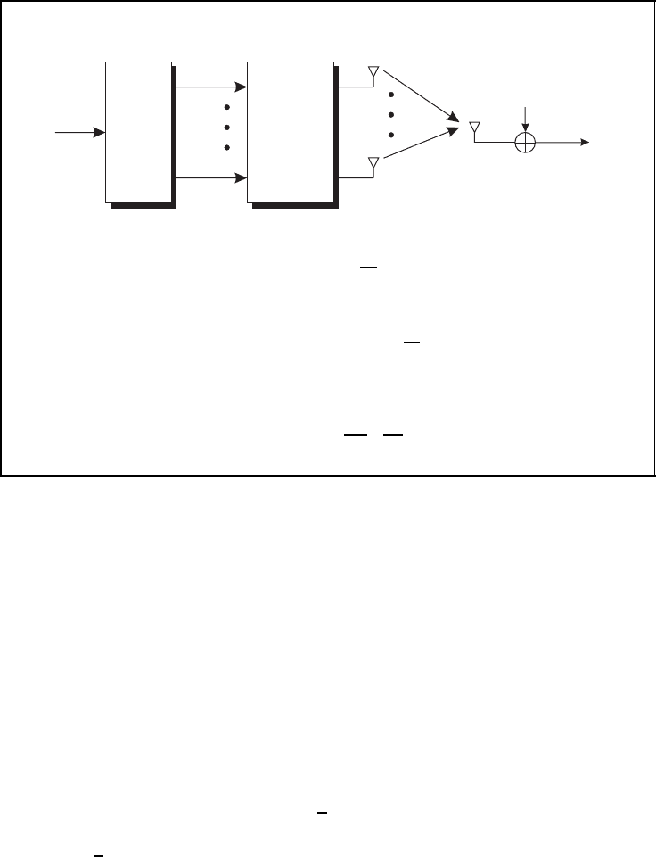
5.4.2 Extension to More than Two Transmit Antennas
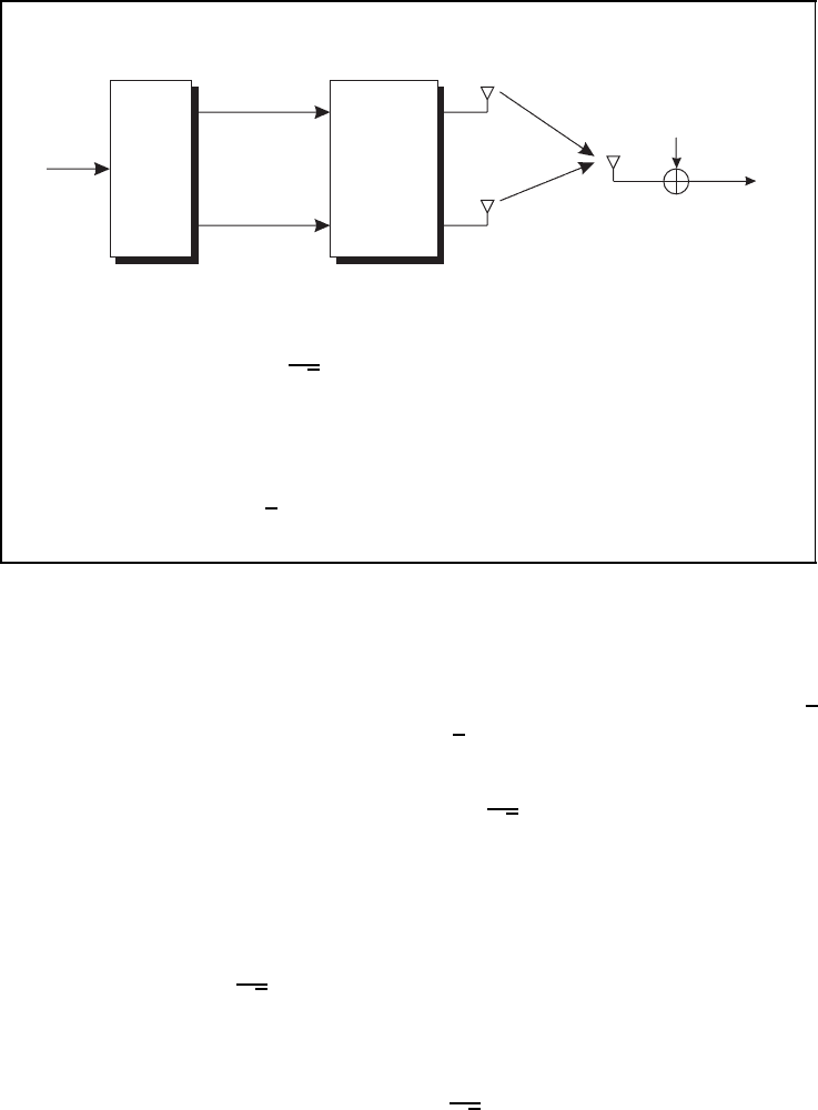
Figure 5.34 shows the basic structure of a space–time block coding system for N
R
= 1
receive antenna. The space–time encoder collects a block of K successive symbols s
µ
and
assigns them onto a sequence of L consecutive vectors
x[k] =
x
1
[k] ··· x
N
T
[k]
T
with 0 ≤ k<L. Therefore, the code matrix X
N
T
consists of K symbols s
1
, ... , s
K
as
well as their conjugate complex counterparts s
∗
1
, ... , s
∗
K
that are arranged in N
T
rows and
L columns. Since the matrix occupies L time instants, the code rate is given in Equation
(5.70). When comparing different space– time coding schemes, one important parameter is
the spectral efficiency η in Equation (5.71). It equals the product of R and the number m
of bits per modulation symbol s[]. Therefore, it determines the average number of bits
that are transmitted per channel use. In order to obtain orthogonal space–time block codes,
the rows in X
N
T
have to be orthogonal, resulting in the orthogonality constraint given in
Equation(5.72).
The factor in front of the identity matrix ensures that the average transmit power per
symbol equals E
s
/T
s
and is independent of N
T
and L. Since X
H
N
T
X
N
T
is a square N
T
× N
T
matrix, the equality
tr
X
N
T
X
H
N
T
= K ·
E
s
T
s
(5.73)
holds. In order to illustrate the condition in Equation (5.73), we will first look at Alamouti’s
scheme. Each of the two symbols is transmitted twice during one block, once as the original
version and a second time as the complex conjugate version. As the total symbol power
should be fixed to E
s
/T
s
, a scaling factor of 1/
√
2 in front of X
2
is required, as already
used on page 258. For general codes where a symbol is transmitted N times (either the
original symbol or its complex conjugate) with full power, the scaling factor 1/
√
N is
obtained. As we will see, some schemes attenuate symbols in X
N
T
differently, i.e. they are
not transmitted each time with full power. Consequently, this has to be considered when
determining an appropriate scaling factor.
SPACE–TIME CODES 261
Orthogonal space–time block codes
s[]
s
1
s
K
demux
X
N
T
(N
T
× L)
matrix
x
1
[k]
x
N
T
[k]
h
1
h
N
T
n[k]
r[k]
■ Code rate
R =
K
L
(5.70)
■ Spectral efficiency
η = m · R = m ·
K
L
(5.71)
■ Orthogonality constraint
X
N
T
X
H
N
T
=
K
N
T
·
E
s
T
s
· I
N
T
(5.72)
Figure 5.34: General structure of orthogonal space–time block codes with N
T
transmit
antennas
Unfortunately, Alamouti’s scheme is the only orthogonal space–time code with rate
R = 1. For N
T
> 2, orthogonal codes exist only for rates R<1. This loss in spectral
efficiency can be compensated for by using larger modulation alphabets, e.g. replacing
Quaternary Phase Shift Keying (QPSK) with 16-QAM, so that more bits per symbol can
be transmitted. However, we know from Subsection 5.1.1 that increasing the modulation
size M leads to higher error rates. Hence, we have to answer the question as to whether the
achievable diversity gain will be larger than the SNR loss due to a change of the modulation
scheme.
Half-rate codes exist for an arbitrary number of transmit antennas. Code matrices for
N
T
= 3 and N
T
= 4 are presented and summarised in Figure 5.35. Both codes achieve the
full diversity degree that equals N
T
. For N
T
= 3, each of the K = 4 symbols occurs 6 times
in X
3
, resulting in a scaling factor of 1/
√
6. With N
T
= 4 transmit antennas, again four
symbols are mapped onto L = 8 time slots, where each symbol is used 8 times, leading to
a factor 1/
√
8.
Figure 5.36 shows two codes with N
T
= 3 and N
T
= 4 (Tarokh et al., 1999a,b). Both
codes again have the full diversity degree and map K = 3 symbols onto L = 4 time slots,
leading to a rate of R = 3/4. In order to distinguish them from the codes presented so
far, we use the notation T
3
and T
4
. For N
T
= 3, the orthogonal space–time code word
is presented in Equation (5.76). Summing the squared magnitudes for each symbol in T
3
262 SPACE–TIME CODES
Orthogonal space–time block codes for R = 1/2
■ N
T
= 3 transmit antennas (L = 8, K = 4)
X
3
=
1
√
6
·
s
1
−s
2
−s
3
−s
4
s
∗
1
−s
∗
2
−s
∗
3
−s
∗
4
s
2
s
1
s
4
−s
3
s
∗
2
s
∗
1
s
∗
4
−s
∗
3
s
3
−s
4
s
1
s
2
s
∗
3
−s
∗
4
s
∗
1
s
∗
2
(5.74)
■ N
T
= 4 transmit antennas (L = 8, K = 4)
X
4
=
1
√
8
·
s
1
−s
2
−s
3
−s
4
s
∗
1
−s
∗
2
−s
∗
3
−s
∗
4
s
2
s
1
s
4
−s
3
s
∗
2
s
∗
1
s
∗
4
−s
∗
3
s
3
−s
4
s
1
s
2
s
∗
3
−s
∗
4
s
∗
1
s
∗
2
s
4
s
3
−s
2
s
1
s
∗
4
s
∗
3
−s
∗
2
s
∗
1
(5.75)
Figure 5.35: Half-rate orthogonal space–time block codes (Tarokh et al., 1999a)
Orthogonal space–time block codes for R = 3/4
■ N
T
= 3 transmit antennas (L = 4, K = 3)
T
3
=
1
√
12
·
2s
1
−2s
∗
2
√
2s
∗
3
√
2s
∗
3
2s
2
2s
∗
1
√
2s
∗
3
−
√
2s
∗
3
√
2s
3
√
2s
3
−s
1
− s
∗
1
+ s
2
− s
∗
2
s
1
− s
∗
1
+ s
2
+ s
∗
2
(5.76)
■ N
T
= 4 transmit antennas (L = 4, K = 3)
T
4
=
1
4
2s
1
−2s
∗
2
√
2s
∗
3
√
2s
∗
3
2s
2
2s
∗
1
√
2s
∗
3
−
√
2s
∗
3
√
2s
3
√
2s
3
−s
1
− s
∗
1
+ s
2
− s
∗
2
s
1
− s
∗
1
+ s
2
+ s
∗
2
√
2s
3
−
√
2s
3
−s
1
− s
∗
1
− s
2
− s
∗
2
−(s
1
+ s
∗
1
+ s
2
+ s
∗
2
)
(5.77)
Figure 5.36: Orthogonal space–time block codes with rate R = 3/4 (Tarokh et al.,
1999a)

SPACE–TIME CODES 263
results in a value of 12. Hence, the scaling factor amounts to 1/
√
12. For the code T
4
, the
summation yields a value of 16, and thus a scaling factor of 0.25.
The detection at the receiver works in the same way as for Alamouti’s scheme. K
¨
uhn
derived the equivalent channel matrices H[X
N
T
] for each space– time block code (K
¨
uhn,
2006). They make it possible to describe the received vector as the product of H[X
N
T
]
and the transmit vector x.
5
Since the columns of these matrices are orthogonal, a simple
multiplication with their Hermitian delivers the desired data symbol estimates ˜s
µ
.
5.4.3 Simulation Results
After the introduction of several orthogonal space –time block codes, we now analyse
their error rate performance. A first comparison regards all discussed schemes with BPSK
modulation. Hence, the spectral efficiencies are different, as shown in Figure 5.37. In the
left-hand diagram, the error rates are depicted versus E
s
/N
0
. Obviously, codes with identical
diversity degrees such as X
3
and T
3
achieve the same error rates because their differing
code rates are not considered. This somehow leads to an unfair comparison. Instead, one
Performance of orthogonal space–time block codes for BPSK
0 5 10 15 20
10
Ŧ5
10
Ŧ4
10
Ŧ3
10
Ŧ2
10
Ŧ1
10
0
0 5 10 15 20
10
Ŧ5
10
Ŧ4
10
Ŧ3
10
Ŧ2
10
Ŧ1
10
0
E
s
/N
0
in dB →
E
b
/N
0
in dB →
BER →
BER →
X
2
X
2
X
3
X
3
X
4
X
4
T
3
T
3
T
4
T
4
(a) error rate versus E
s
/N
0
(b) error rate versus E
b
/N
0
Figure 5.37: Bit error rates for different orthogonal STBCs with BPSK and code rates
R(X
2
) = 1, R(X
3
) = R(X
4
) = 0.5 and R(T
3
) = R(T
4
) = 0.75 (AWGN reference: bold
line). Reproduced by permission of John Wiley & Sons, Ltd
5
For the code matrices T
3
and T
4
, a real-valued description is required, i.e. the linear equation system does
not contain complex symbols and their conjugates, but only real and imaginary parts of all components.
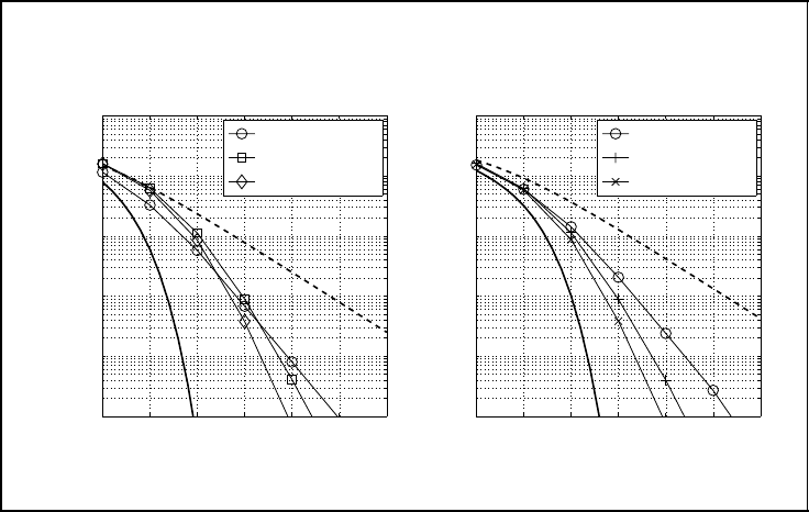
264 SPACE–TIME CODES
should depict the error rates versus E
b
/N
0
, where E
s
= RE
b
holds. First, the corresponding
results in the right-hand diagram illustrate that the slopes of all curves are still the same
because using E
b
/N
0
does not change the diversity degree. However, horizontal shifts
can be observed, so that T
4
now yields the best results. The higher diversity degree of 4
overcompensates for the lower code rate compared with Alamouti’s scheme. On the other
hand, the half-rate codes lose most, and Alamouti’s code outperforms X
3
over a wide range
of E
b
/N
0
values. As a reference, the AWGN curve is plotted as a bold line. Certainly, it
cannot be reached by any of the codes owing to a maximum diversity degree of only 4.
Next, we would like to compare different space–time coding schemes under the con-
straint of identical spectral efficiencies. Therefore, the modulation schemes have to be
adapted. In order to achieve a spectral efficiency η = 2 bit/s/Hz, Alamouti’s scheme has
to employ QPSK, while the codes X
3
and X
4
with R = 1/2 have to use 16-QAM or 16-
PSK. Owing to the better performance of 16-QAM, we confine ourselves to that modulation
scheme. For η = 3 bit/s/Hz, 8-PSK is chosen for X
2
and 16-QAM for T
3
and T
4
.
The results are depicted in Figure 5.38. On account of to the higher robustness of
QPSK compared with 16-QAM the code X
2
performs better than X
3
and X
4
for low
and medium signal-to-noise ratios (left-hand diagram). Asymptotically, the diversity gain
becomes dominating owing to the larger slope of the curves, so that X
3
and X
4
are bet-
ter for large SNR. The error rates of all space–time codes are significantly better than
simple QPSK transmission without diversity, although the AWGN performance is not
reached.
Performance of orthogonal space–time block codes
0 5 10 15 20 25 30
10
Ŧ5
10
Ŧ4
10
Ŧ3
10
Ŧ2
10
Ŧ1
10
0
0 5 10 15 20 25 30
10
Ŧ5
10
Ŧ4
10
Ŧ3
10
Ŧ2
10
Ŧ1
10
0
E
b
/N
0
in dB →E
b
/N
0
in dB →
BER →
BER →
X
2
, QPSK
X
3
, 16-QAM
X
4
, 16-QAM
X
2
, 8-PSK
T
3
, 16-QAM
T
4
, 16-QAM
(a) η = 2 bit/s/Hz
(b) η = 3 bit/s/Hz
Figure 5.38: Bit error rates for different orthogonal STBCs with η = 2 bit/s/Hz and
η = 3 bit/s/Hz (AWGN reference: bold solid line; Rayleigh reference: bold dashed line)
SPACE–TIME CODES 265
Diagram (b) illustrates results for a spectral efficiency η = 3 bit/s/Hz. Owing to the
relative high code rate R = 0.75 for T
3
and T
4
, only four instead of three bits per symbol
have to be transmitted, leading to the modulation schemes 8-PSK and 16-QAM. As we
know from Subsection 5.1.1, 16-QAM performs nearly as well as 8-PSK. Hence, the larger
diversity gain for T
3
and T
4
is visible over the whole range of SNRs, and the weaker
performance of 8-PSK compared with 16-QAM is negligible.
5.5 Spatial Multiplexing
5.5.1 General Concept
In the previous section, coding in space and time has been discussed, mainly for systems
with multiple transmit but only a single receive antenna. This approach aims to increase
the diversity degree and, hence, the reliability of a communication link. The achievable
data rate is not changed or even decreased by code rates R<1. By Contrast, multiple
antennas at transmitter and receiver make it possible to increase the data rate by exploiting
the resource space without increasing the bandwidth. This multiplexing gain is possible
by transmitting independent data streams over spatially separated channels. We will see
later that diversity and multiplexing gains can be obtained simultaneously by using a more
general description such as linear dispersion codes.
In this section, we assume frequency-non-selective fading channels between each pair
of transmit and receive antennas that can be modelled by complex-valued coefficients
whose real and imaginary parts are independent and Gaussian distributed. Linear modulation
schemes such as M-PSK or M-QAM are used at the transmitter. The improved throughput
by increasing M comes along with a larger sensitivity to noise and interference. Moreover,
the computational complexity of some detection schemes grows exponentially with the
number of the possible transmit vectors and, thus, with M. As stated in Section 5.2, the
general system model can be described by
r = H · x + n (5.78)
Principally, two cases have to be distinguished.
Exploiting Eigenmodes of Spatial Channel
If channel knowledge is available at transmitter and receiver side, we saw in Subsec-
tion 5.3.1 that capacity can be achieved by exploiting the channel’s eigenmodes and
applying the waterfilling principle. The maximum number of non-zero eigenmodes equals
the rank of H and is upper bounded by min{N
T
,N
R
}. However, it has to be mentioned that
the number of parallel data streams that can be supported also depends on the available
transmit power σ
2
X
> 0 and may be smaller than the rank of H.
The transmission strategy is accomplished by performing a singular value decomposition
of the channel matrix H = U
H
H
V
H
H
. If the waterfilling solution distributes the total
transmit power onto r data streams with powers λ
i
, the transmit vector is constructed by
x = V
X
·
1/2
X
· s,