Patrick F. Dunn, Measurement, Data Analysis, and Sensor Fundamentals for Engineering and Science, 2nd Edition
Подождите немного. Документ загружается.

76 Measurement and Data Analysis for Engineering and Science
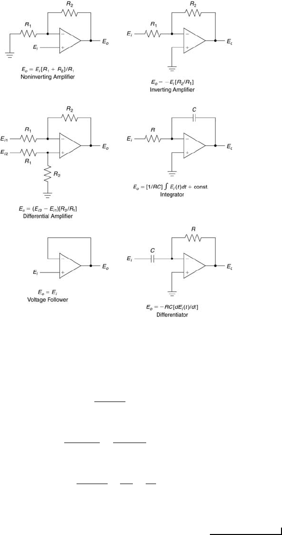
FIGURE 3.9
Other operational amplifier configurations.
This implies
E
A
=
R
2
R
1
+ R
2
E
i2
.
Application of Kirchhoff’s first law at node B yields
E
i1
− E
B
R
1
=
E
B
− E
o
R
2
.
This gives
E
B
=
R
1
R
2
R
1
+ R
2
E
i1
R
1
+
E
o
R
2
.
Now E
A
= E
B
because of the op amp’s high internal open-loop gain. Equating the
expressions for E
A
and E
B
gives the desired result, E
o
= (E
i2
− E
i1
)(R
2
/R
1
).
Measurement Systems 77
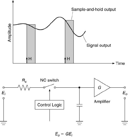
FIGURE 3.10
The sample-and-hold circuit.
In fact, op amps are the foundations of many signal-conditioning circuits.
One example is the use of an op amp in a simple sample-and-hold circuit, as
shown in Figure 3.10. In this circuit, the output of the op amp is held at a
constant value (= GE
i
) for a period of time (usually several microseconds)
after the normally-closed (NC) switch is held open using a computer’s logic
control. Sample-and-hold circuits are common features of A/D converters,
which are covered later in this chapter. They provide the capability to si-
multaneously acquire the values of several signals. These values are then
held by the circuit for a sufficient period of time until all of them are stored
in the computer’s memory.
Quite often in measurement systems, a differential signal, such as that
across the output terminals of a Wheatstone bridge, has a small (on the
order of tens of millivolts), DC-biased (on the order of volts) voltage. When
this is the case, it is best to use an instrumentation amplifier. An instru-
mentation amplifier is a high-gain, DC-coupled differential amplifier with a
single output, high input impedance, and high CMRR [13]. This configura-

78 Measurement and Data Analysis for Engineering and Science
tion assures that the millivolt-level differential signal is amplified sufficiently
and that the DC-bias and interference-noise voltages are rejected.
3.5 Filters
Another measurement system component is the filter. Its primary purpose
is to remove signal content at unwanted frequencies. Filters can be passive
or active. Passive filters are comprised of resistors, capacitors, and induc-
tors that require no external power supply. Active filters use resistors and
capacitors with operational amplifiers, which require power. Digital filtering
also is possible, where the signal is filtered after it is digitized.
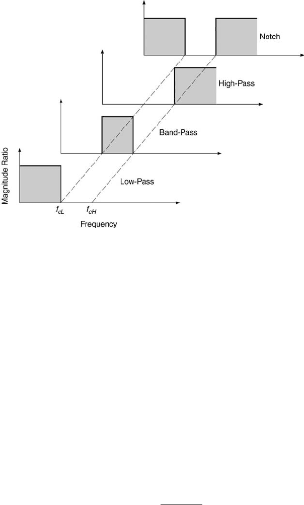
The most common types of ideal filters are presented in Figure 3.11.
The term ideal implies that the magnitude of the signal passing through the
filter is not attenuated over the desired passband of frequencies. The term
band refers to a range of frequencies and the term pass denotes the unaltered
passing. The range of frequencies over which the signal is attenuated is called
the stopband. The low-pass filter passes lower signal frequency content up
to the cut-off frequency, f
c
, and the high-pass filter passes content above
f
c
. A low-pass filter and high-pass filter can be combined to form either a
band-pass filter or a notch filter, each having two cut-off frequencies, f
cL
and f
cH
. Actual filters do not have perfect step changes in amplitude at
their cut-off frequencies. Rather, they experience a more gradual change,
which is characterized by the roll-off at f
c
, specified in terms of the ratio of
amplitude change to frequency change.
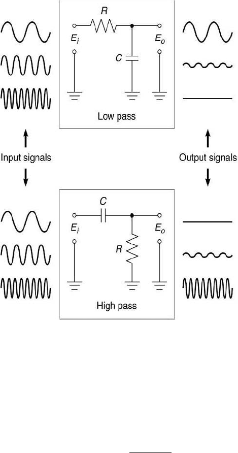
The simplest filter can be made using one resistor and one capacitor. This
is known as a simple RC filter, as shown in Figure 3.12. Referring to the top
of that figure, if E
o
is measured across the capacitor to ground, it serves as
a low-pass filter. Lower frequency signal content is passed through the filter,
whereas high frequency content is not. Conversely, if E
o
is measured across
the resistor to ground, it serves as a high-pass filter, as shown in the bottom
of the figure. Here, higher frequency content is passed through the filter,
whereas lower frequency content is not. For both filters, because they are
not ideal, some fraction of intermediate frequency content is passed through
the filter. The time constant of the simple RC filter, τ , equals RC. A unit
balance shows that the units of RC are (V/A)·(C/V) or s. An actual filter
differs from an ideal filter in that an actual filter alters both the magnitude
and the phase of the signal, but it does not change its frequency.
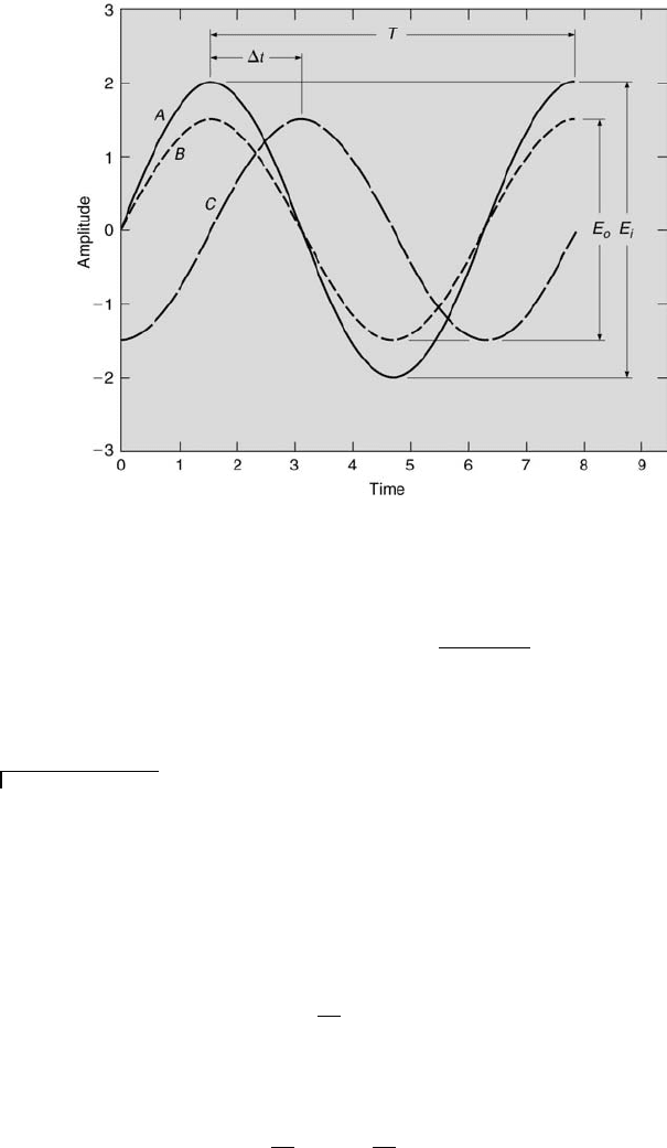
Actual filter behavior can be understood by first examining the case
of a simple sinusoidal input signal to a filter. This is displayed in Figure
3.13. The filter’s input signal (denoted by A in the figure) has a peak-to-
peak amplitude of E
i
, with a one-cycle period of T seconds. That is, the
signal’s input frequency, f, is 1/T cycles/s or Hz. Sometimes the input
Measurement Systems 79
FIGURE 3.11
Ideal filter characteristics.
frequency is represented by the circular frequency, ω, which has units of
rad/s. So, ω = 2πf . If the filter only attenuated the input signal’s amplitude,
it would appear as signal B at the filter’s output, having a peak-to-peak
amplitude equal to E
0
. In fact, however, an actual filter also delays the
signal in time by ∆t between the filter’s input and output, as depicted by
signal C in the figure. The output signal is said to lag the input signal by ∆t.
This time lag can be converted into a phase lag or phase shift by noting
that ∆t/T = φ/360
◦
, which implies that φ = 360
◦
(∆t/T ). By convention,
the phase lag equals −φ. The magnitude ratio, M (f), of the filter equals
E
o
(f)/E
i
(f). For different input signal frequencies, both M and φ will have
different values.
Analytical relationships for M(f ) and φ(f) can be developed for simple
filters. Typically, M and φ are plotted each versus ωτ or f/f
c
, both of which
are dimensionless, as shown in Figures 4.3 and 4.4 of Chapter 4. The cutoff
frequency, ω
c
, is defined as the frequency at which the power is one-half
of its maximum. This occurs at M = 0.707, which corresponds to ωτ = 1
for first-order systems, such as simple filters [14]. Thus, for simple filters,
ω
c
= 1/(RC) or f
c
= 1/(2πRC). In fact, for a simple low-pass RC filter,
M(ω) = 1/
p
1 + (ωτ)
2
(3.14)
and
φ = −tan
−1
(ωτ). (3.15)
80 Measurement and Data Analysis for Engineering and Science
FIGURE 3.12
Simple RC low-pass and high-pass filters.
Using these equations, M (ω = 1/τ) = 0.707 and φ = −45
◦
. That is, at
an input frequency equal to the cut-off frequency of an actual RC low-pass
filter, the output signal’s amplitude is 70.7 % of the signal’s input amplitude
and it lags the input signal by 45
◦
. For an RC high-pass filter, the phase
lag equation is given by Equation 3.15 and the magnitude ratio is
M(ω) = ωτ /
p
1 + (ωτ )
2
. (3.16)
These equations are derived in Chapter 4.
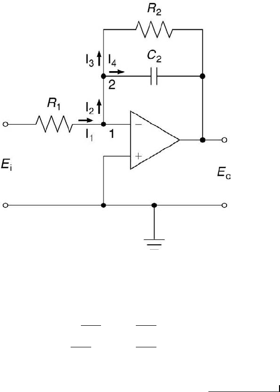
An active low-pass Butterworth filter configuration is shown in Figure
3.14. Its time constant equals R
2
C
2
, and its magnitude ratio and phase
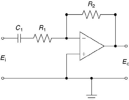
lag are given by Equations 3.14 and 3.15, respectively. An active high-pass
Butterworth filter configuration is displayed in Figure 3.15. Its time constant
equals R
1
C
1
, and its phase lag is given by Equation 3.15. Its magnitude ratio
Measurement Systems 81
FIGURE 3.13
Generic filter input/output response characteristics.
is
M(ω) = [R
2
/R
1
] · [ωτ/
p
1 + (ωτ )
2
]. (3.17)
Other classes of filters have different response characteristics. Refer to [13]
for detailed descriptions or [4] for an overview.
Example Problem 3.5
Statement: For the circuit depicted in Figure 3.14, determine the equation relating
the output voltage E
o
to the input voltage E
i
.
Solution: The op amp’s major attributes assure that no current flows into the op
amp and that the voltage difference between the two input terminals is zero. Assigning
currents and nodes as shown in Figure 3.14 and applying Kirchhoff’s current law and
Ohm’s law to node 1 gives
I
1
= I
2
E
1
R
1
= I
2
.
Applying Kirchhoff’s current law and Ohm’s law at node 2 results in
I
2
= I
3
+ I
4
E
1
R
1
= −
E
0
R
2
− C
2
˙
E
0
.
Dividing the above equation through by C
2
and rearranging terms yields
82 Measurement and Data Analysis for Engineering and Science
FIGURE 3.14
The active low-pass Butterworth filter.
E
1
C
2
R
1
= −
E
0
C
2
R
2
−
˙
E
0
,
˙
E
0
+
1
C
2
R
2
E
0
= −
1
C
2
R
1
E
1
.
This is a first-order, ordinary differential equation whose method of solution is presented
in Chapter 4.
Digital filters operate on a digitally converted signal. The filter’s cutoff
frequency adjusts automatically with sampling frequency and can be as
low as a fraction of a Hz [13]. An advantage that digital filters have over
their analog counterparts is that digital filtering can be done after data has
been acquired. This approach allows the original, unfiltered signal content to
be maintained. Digital filters operate by successively weighting each input
signal value that is discretized at equal-spaced times, x
i
, with k number of
weights, h
k
. The resulting filtered values, y
i
, are given by
y
i
=
∞
X
k=−∞
h
k
x
i−k
. (3.18)
Measurement Systems 83
FIGURE 3.15
The active high-pass Butterworth filter.
The values of k are finite for real digital filters. When the values of h
k
are
zero except for k ≥ 0, the digital filter corresponds to a real analog filter.
Symmetrical digital filters have h
−k
= h
k
, which yield phase shifts of 0
◦
or
180
◦
.
Digital filters can use their output value for the i-th value to serve as an
additional input for the (i+1)-th output value. This is known as a recursive
digital filter. When there is no feedback of previous output values, the filter
is a nonrecursive filter. A low-pass, digital recursive filter [13] can have
the response
y
i
= ay
i−1
+ (1 − a)x
i
, (3.19)
where a = exp(−t
s
/τ). Here, t
s
denotes the time between samples and τ the
filter time constant, which equals RC. For this filter to operate effectively,
τ >> t
s
. Or, in other words, the filter’s cut-off frequency must be much less
than the Nyquist frequency. The latter is covered extensively in Chapter 10.
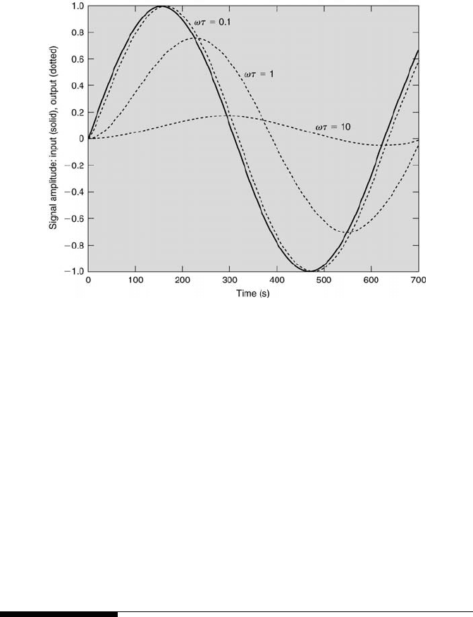
An example of this digital filtering algorithm is shown in Figure 3.16. The
input signal of sin(0.01t) is sampled 10 times per second. Three output cases
are plotted, corresponding to the cases of τ = 10, 100, and 1000. Because
of the relatively high sample rate used, both the input and output signals
appear as analog signals, although both actually are discrete. When ωτ is
less than one, there is little attenuation in the signal’s amplitude. In fact,
the filtered amplitude is 99 % of the original signal’s amplitude. Also, the
filtered signal lags the original signal by only 5
◦
. At ωτ = 1, the amplitude
attenuation factor is 0.707 and the phase lag is 45
◦
. When ωτ = 10, the
84 Measurement and Data Analysis for Engineering and Science
FIGURE 3.16
Digital low-pass filtering applied to a discretized sine wave.
attenuation factor is 0.90 and the phase lag is 85
◦
. This response mirrors
that of an analog filter, as depicted in Figure 3.13 and described further in
Chapter 4.
Almost all signals are comprised of multiple frequencies. At first, this
appears to complicate filter performance analysis. However, almost any in-
put signal can be decomposed into the sum of many sinusoidal signals of
different amplitudes and frequencies. This is the essence of Fourier analysis,
which is examined in Chapter 9. For a linear, time-invariant system such
as a simple filter, the output signal can be reconstructed from its Fourier
component responses.
3.6 Analog-to-Digital Converters
The last measurement system element typically encountered is the A/D
converter. This component serves to translate analog signal information into
the digital format that is used by a computer. In the computer’s binary
world, numbers are represented by 0’s and 1’s in units called bits. A bit
value of either 0 or 1 is stored physically in a computer’s memory cell using
a transistor in series with a capacitor. An uncharged or charged capacitor
Measurement Systems 85
On Decimal Value
4
2
1
Conversion
Decimal
Off Decimal Value
0
0
0
Process
Equivalent
Binary Representation
0
0
0
0 · 4 + 0 · 2 + 0 · 1
0
0
0
1
0 · 4 + 0 · 2 + 1 · 1
1
0
1
0
0 · 4 + 1 · 2 + 0 · 1
2
0
1
1
0 · 4 + 1 · 2 + 1 · 1
3
1
0
0
1 · 4 + 0 · 2 + 0 · 1
4
1
0
1
1 · 4 + 0 · 2 + 1 · 1
5
1
1
0
1 · 4 + 1 · 2 + 0 · 1
6
1
1
1
1 · 4 + 1 · 2 + 1 · 1
7
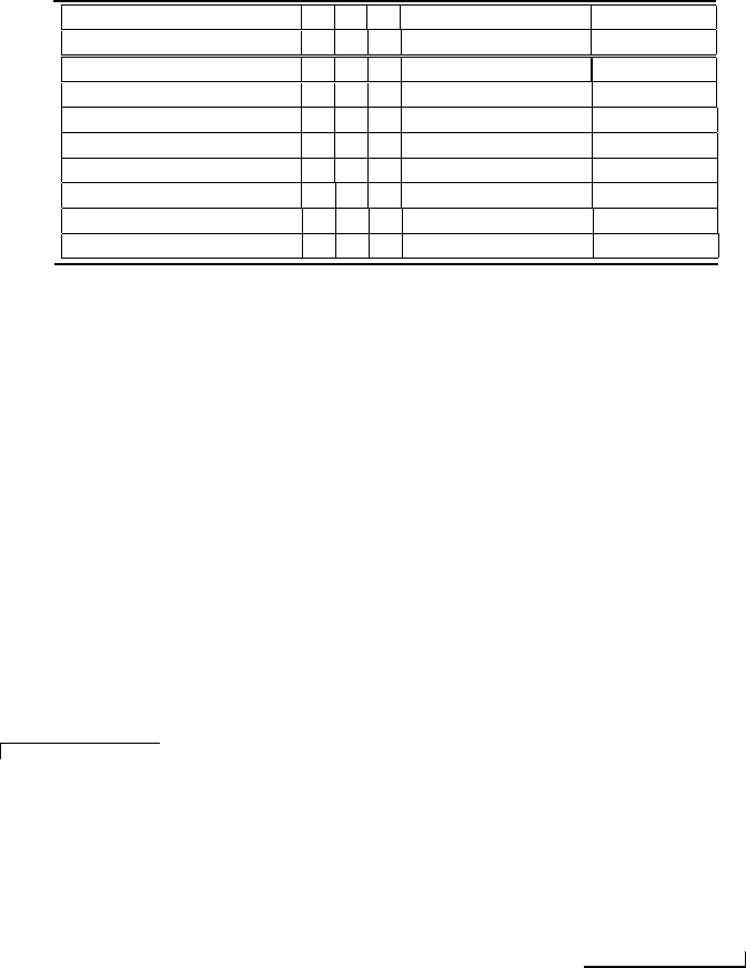
TABLE 3.1
Binary to decimal conversion.
represents the value of 0 or 1, respectively. Similarly, logic gates comprised
of on-off transistors perform the computer’s calculations.
Decimal numbers are translated into binary numbers using a decimal-to-
binary conversion scheme. This is presented in Table 3.1 for a 3-bit scheme.
A series of locations, which are particular addresses, are assigned to a series
of bits that represent decimal values corresponding from right to left to in-
creasing powers of 2. The least significant (right-most) bit (LSB) represents
a value of 2
0
, whereas the most significant (left-most) bit (MSB) of an M-bit
scheme represents a value of 2
M−1
. For example, for the 3-bit scheme shown
in Table 3.1, when the LSB and MSB are on and the intermediate bit is off,
the binary equivalent 101 of the decimal number 5 is stored.
Example Problem 3.6
Statement: Convert the following decimal numbers into binary numbers: [a] 5, [b]
8, and [c] 13.
Solution: An easy way to do this type of conversion is to note that the power of 2 in
a decimal number is equal to the number of zeros in the binary number. [a] 5 = 4 + 1
= 2
2
+ 1. Therefore, the binary equivalent of 5 is 100 + 1 = 101. [b] 8 = 2
3
. Therefore,
the binary equivalent of 8 is 1000. [c] 13 = 8 + 4 + 1 = 2
3
+ 2
2
+ 1. Therefore, the
binary equivalent of 13 is 1000 + 100 + 1 = 1101.
There are many methods used to perform analog-to-digital conversion
electronically. The two most common ones are the successive-approximation
and ramp-conversion methods. The successive-approximation method
utilizes a D/A converter and a differential op amp that subtracts the analog
input signal from the D/A converter’s output signal. The conversion pro-
cess begins when the D/A converter’s signal is incremented in voltage steps
from 0 volts using digital logic. When the D/A converter’s signal rises to
within volts of the analog input signal, the differential op amp’s output,