Patrick F. Dunn, Measurement, Data Analysis, and Sensor Fundamentals for Engineering and Science, 2nd Edition
Подождите немного. Документ загружается.


86 Measurement and Data Analysis for Engineering and Science
Term
Formula
M = 8
M = 12
MSB Value
2
M−1
128
2048
LSB Value
2
0
1
1
Maximum Possible Value
2
M
− 1
255
4095
Minimum Possible Value
0
0
0
Number of Possible Values
2
M
256
4096
MSB Weight
2
−1
1/2
1/2
LSB Weight
2
−M
1/256
1/4096
Resolution, Q (mV/bit)
E
F SR
/2
M
39.06
2.44
for E
F SR
= 10 V
Dynamic Range (dB)
20 log
10
(Q/Q
o
)
−28
−52
Absolute Quantization Error (mV)
±Q/2
±19.53
±1.22
TABLE 3.2
M-bit terminology.
now equal to volts, causes the logic control to stop incrementing the D/A
converter and tells the computer to store the converter’s digital value. The
ramp-conversion method follows a similar approach by increasing a volt-
age and comparing it to the analog input signal’s voltage. The increasing
signal is produced using an integrating op amp configuration, in which the
op amp configuration is turned on through a switch controlled by the com-
puter. In parallel, the computer starts a binary counter when the op amp
configuration is turned on. When the analog input and op amp configura-
tion signals are equal, the computer stops the binary counter and stores its
values.
The terminology used for an M-bit A/D converter is summarized in
Table 3.2. The values listed in the table for the LSB and MSB are when
the bit is on. The bit equals 0 when it is off. The minimum decimal value
that can be represented by the converter equals 0. The maximum value
equals 2
M
− 1. Thus, 2
M
possible values can be represented. The weight of
a bit is defined as the value of the bit divided by the number of possible
values. The resolution and absolute quantization error are based on an M-
bit, unipolar A/D converter with a full-scale range (FSR) equal to 10.00
V, where Q
o
= 1000 mV/bit. Most A/D converters used today are 12-bit
or 16-bit converters, providing signal resolutions of 2.44 mV/bit and 0.153
mV/bit, respectively.
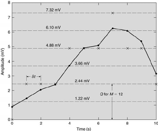
An analog signal is continuous in time and therefore comprised of an
infinite number of values. An M-bit A/D converter, however, can only rep-
resent the signal’s amplitude by a finite set of 2
M
values. This presents a
signal resolution problem. Consider the analog signal represented by the
solid curve shown in Figure 3.17. If the signal is sampled discretely at δt
time increments, it will be represented by the values indicated by the open
Measurement Systems 87
FIGURE 3.17
Schematic of analog-to-digital conversion.
circles. With discrete sampling, only the signal values between the sample
times are lost, but the signal’s exact amplitude values are maintained at each
sample time. Yet, if this information is stored using the digital sampling
scheme of the A/D converter, the signal’s exact amplitude values also are
lost. In fact, for the 12-bit A/D converter used to sample the signal shown in
Figure 3.17, the particular signal is represented by only four possible values
(0 mV, 2.44 mV, 4.88 mV, and 7.32 mV), as indicated by the ×’s in the
figure. Thus, a signal whose amplitude lies within the range of ±Q/2 of a
particular bit’s value will be assigned the bit’s value. This error is termed
the absolute quantization error of an A/D converter.
Quite often, if a signal’s amplitude range is on the order of the A/D
converter’s resolution, an amplifier will be used before the A/D converter to
gain the signal’s amplitude and, therefore, reduce the absolute quantization
error to an acceptable level. An alternative approach is to use an A/D board
with better resolution, but, almost always, this is more expensive.
88 Measurement and Data Analysis for Engineering and Science
System
Variable
Sensor/
Signal
Signal
no.
(result)
Transducer
Conditioner
Processor
1
pressure
strain gage,
amplifier,
A/D converter,
(→velocity)
Wheatstone bridge
filter
computer
2
force
strain gage,
amplifiers,
digital
(→thrust)
Wheatstone bridge
filter
oscilloscope
3a
pressure
piezoresistive
amplifier
microcontroller
(→velocity)
element
system
3b
acceleration
differential-capacitive
amplifier
microcontroller
(acceleration)
structure
system
TABLE 3.3
The elements of three measurement systems.
3.7 Example Measurement Systems
The designs of three actual measurement systems are presented in this sec-
tion to illustrate the different choices that can be made. The final design of
each system involves many trade-offs between the accuracy and the cost of
their components. The elements of each of these systems are summarized in
Table 3.3. Several major differences can be noted. The most significant are
the choices of the sensor/transducer and of the signal processing system.
These are dictated primarily because of the environments in which each is
designed to operate. System 1 is developed to be located near the test sec-
tion of a subsonic wind tunnel, to be placed on a small table, and to use an
existing personal computer. System 2 is designed to be located on one cart
that can be moved to a remote location when the rocket motor is tested.
-
-
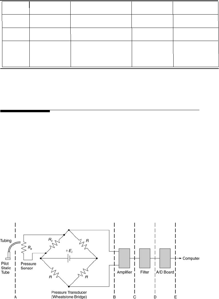
FIGURE 3.18
An example pressure measurement system.

Measurement Systems 89
Component
Conditions
Unknown
Environment
T = 294 K, p = 1 atm
ρ, ∆p, F ,
L
, δR
Diaphragm
L
= 0.001 × F , A = 1 cm
2
, C
o
= 0.001
Strain Gage
R = 120 Ω at 294 K
Wheatstone Bridge
All R = 120 Ω at 294 K, E
i
= 5 V
E
o
Amplifier
Non-inverting op amp, R
1
= 1 MΩ
R
2
Filter
Low-pass with R = 1 MΩ, C = 1 µF
A/D Converter
E
F SR
= 10 V, Q < 1 mV/bit
M
TABLE 3.4
Velocity measurement system conditions.
A digital oscilloscope is chosen for its convenience of remote operation and
its triggering and signal storage capabilities. System 3 is developed to be
placed inside of a 2 in. internal diameter model rocket fuselage and then
launched over 100 m into the air with accelerations and velocities as high as
60 m/s
2
(∼6 g) and 50 m/s, respectively. These conditions constrain the size
and weight of the measurement system package. A small, battery-powered,
microcontoller-based data acquisition system with an A/D converter, am-
plifier, and memory is designed specifically for this purpose [15].
Measurement system 1 is designed to measure the velocity of air flowing
in a wind tunnel, as shown in Figure 3.18. Its pitot-static tube is located
within a wind tunnel. The pitot-static tube and tubing are passive and
simply transmit the total and static pressures to a sensor located outside
the wind tunnel. The actual sensor is a strain gage mounted on a flexible
diaphragm inside a pressure transducer housing. The static pressure port is
connected to one side of the pressure transducer’s diaphragm chamber; the
total pressure port to the other side. This arrangement produces a flexure of
the diaphragm proportional to the dynamic pressure (the physical stimulus)
that strains the gage and changes its resistance (the electrical impulse).
This resistance change imbalances a Wheatstone bridge operated in the
deflection mode, producing a voltage at station B. Beyond station B, the
signal is amplified, filtered, converted into its digital format, and finally
stored by the computer. Another example measurement system, used to
measure temperature, is considered in this chapter’s homework problems.
The velocity measurement system is to be designed such that the input
voltage to the A/D converter, E
D
, is 10 V when the wind tunnel velocity is
100 m/s. The design also is subject to the additional conditions specified in
Table 3.4. Given these constraints, the desired input and output character-
istics of each measurement system element can be determined for stations
A through E, as denoted in Figure 3.18. Determination of the performance
characteristics for each stage is as follows:
90 Measurement and Data Analysis for Engineering and Science
• Station A: The velocity, V , of 100 m/s yields a dynamic pressure, ∆p,
of 5700 N/m
2
using Bernoulli’s equation, ∆p = 0.5ρV
2
. The density, ρ,
equals 1.14 kg/m
3
, as determined using Equation 11.1.
• Station B: The dynamic pressure produces a force, F , on the diaphragm,
which has an area, A, equal to 1 cm
2
. The resulting force is 0.57 N, noting
that the force equals the pressure difference across the diaphragm times
its area. A longitudinal strain on the diaphragm,
L
, is produced by
F , where
L
= C
o
F . The resulting strain is 5.7 × 10
−4
. According to
Equation 3.7, this gives δR/R = 1.14 × 10
−3
. The Wheatstone bridge is
operated in the deflection method mode with all resistances equal to 120
Ω at 294 K and V = 0 m/s. The output voltage, E
o
= E
B
, is determined
using Equation 2.29 and equals 1.42 mV.
• Station C: The relatively low output voltage from the Wheatstone bridge
needs to be amplified to achieve the A/D input voltage, E
D
, of 10 V.
Assuming that the filter’s magnitude ratio is unity, the gain of the am-
plifier equals E
D
/E
B
, which is 10/0.142 or 70.4. An op amp in the
non-inverting configuration is used. Its input-output voltage relation is
given in Figure 3.9. E
o
/E
i
= 70.4 and R
1
= 1 MΩ implies that R
2
equals 69.4 MΩ.
• Station D: The measurement system operates at steady state. The volt-
ages are DC, having zero frequency. Thus, the filter’s magnitude ratio
is unity. Therefore, E
D
= E
C
.
• Station E: If the A/D converter has a full scale input voltage, E
F SR
, of
10 V, then the converter is at its maximum input voltage when V = 100
m/s. The relationship between the A/D converter’s E
F SR
, Q, and the
number of converter bits, M, is presented in Table 3.2. Choosing M = 12
does not meet the constraint. The next choice is M = 16. This yields
Q = 0.153 mV/bit, which satisfies the constraint.
Many choices can be made in designing this system. For example, the
supply voltage to the Wheatstone bridge could be increased from 5 V to
10 V or 12 V, which are common supply voltages. This would increase
the output voltage of the bridge and, therefore, require less amplification
to meet the 10 V constraint. Other resistances can be used in the bridge.
A different strain gage can be used on the diaphragm. If the system will
be used for non-steady velocity measurements, then the time responses of
the tubing, the diaphragm, and the filter need to be considered. Each can
affect the magnitude and the phase of the signal. The final choice of specific
components truly is an engineering decision.
Next, examine measurement system 2 that is designed to acquire thrust
as a function of time of a model rocket motor. The first element of the mea-
surement system consists of an aluminum, cantilevered beam with four 120
Ω strain gages, similar to that shown schematically in Figure 2.11. These
Measurement Systems 91
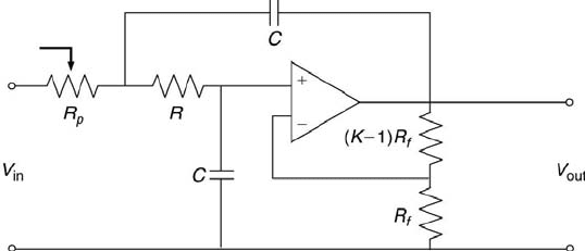
FIGURE 3.19
Two-pole, low-pass Sallen-and-Key filter.
strain gages comprise the legs of a Wheatstone bridge. The maximum out-
put of the bridge is approximately 50 mV. So, the output of the bridge is
connected to an instrumentation amplifier with a gain of 100 and then to a
variable-gain, operational amplifier in the inverting configuration. This al-
lows the signal’s amplitude to be adjusted for optimum display and storage
by the digital oscilloscope. A two-pole, low-pass Sallen-and-Key filter [13]
receives the second amplifier’s output, filters it, and then passes it to the
digital oscilloscope. The filter’s schematic is shown in Figure 3.19. Typical
filter parameter values are R = 200 kΩ, R
f
= 200 kΩ, C = 0.1 µF, and K
= 1.586. A low-pass filter is used to eliminate the ∼30 Hz component that
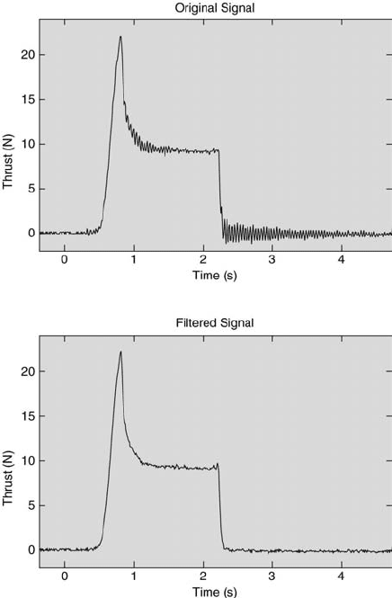
is the natural frequency of the cantilevered beam. The original and filtered
rocket motor thrust data as a function of time are shown in Figure 3.20.
The effect of the low-pass filter is clearly visible. Additional details about
the experiment can be found on the text web site.
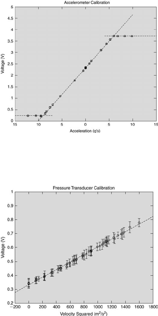
Finally, consider the design of measurement system 3, to be used re-
motely in a model rocket to acquire the rocket’s acceleration and velocity
data during ascent. The measurement system hardware consists of two sen-
sor/transducers, one for pressure and the other for acceleration, and a board
containing a microcontroller-based data acquisition system. The pressure
transducer includes an integrated silicon pressure sensor that is signal condi-
tioned, temperature compensated, and calibrated on-chip. A single piezore-
sistive element is located on a flexible diaphragm. Total and static pressure
ports on the rocket’s nose cone are connected with short tubing to each side
of the flexible diaphragm inside the transducer’s housing. The difference in
pressure causes the diaphragm to deflect, which produces an output voltage
that is directly proportional to the differential pressure, which for this case is
the dynamic pressure. The single-axis ±5 g accelerometer contains a polysil-
icon surface sensor. A differential capacitor structure attached to the surface
deflects under acceleration, causing an imbalance in its the capacitor circuit.
This produces an output voltage that is linearly proportional to the accel-
eration. The accelerometer and pressure transducer calibration curves are
92 Measurement and Data Analysis for Engineering and Science
FIGURE 3.20
Original and filtered rocket motor thrust signal.
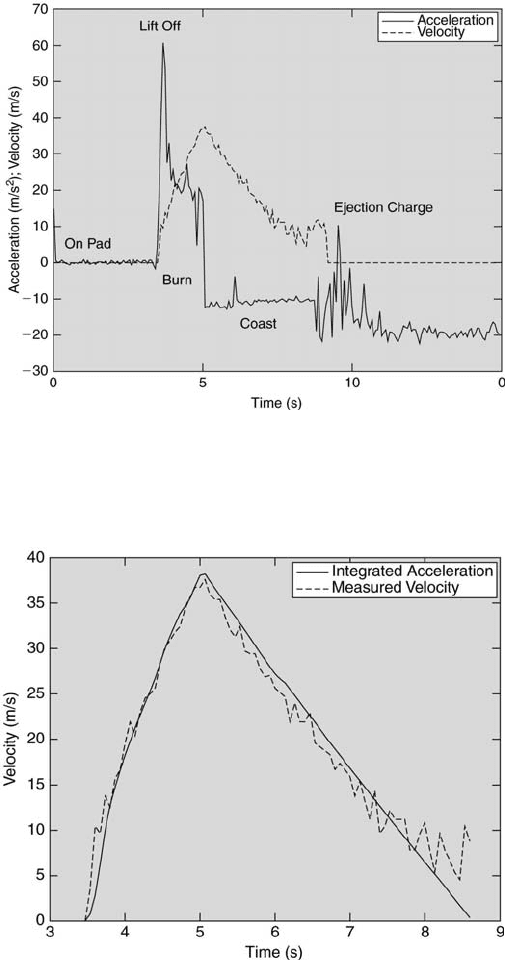
shown in Figures 3.21 and 3.22, respectively. Both sensor/tranducer outputs
are each routed into an amplifier with a gain of 16 and then to the inputs of
a 12-bit A/D converter. The output digital signals are stored directly into
memory (256 kB). The measurement system board has a mass of 33 g and
dimensions of 4.1 cm by 10.2 cm. The on-board, 3.3 V, 720 mAh Li-battery
that powers the entire system has a mass of 39 g. All of the on-board data
is retrieved after capture and downloaded into a laptop computer. A sample
of the reconstructed data is displayed in Figure 3.23 The rocket’s velocity
in time can be determined from the pressure transducer’s output. This is
compared to the time integral of the rocket’s acceleration in Figure 3.24.
Finally, this information can be used with the information on the rocket’s
drag to determine the maximum altitude of the rocket.
Measurement Systems 93
FIGURE 3.21
Calibration of the accelerometer.
FIGURE 3.22
Calibration of the pressure transducer.
94 Measurement and Data Analysis for Engineering and Science
FIGURE 3.23
Example rocket velocity and acceleration data.
FIGURE 3.24
Integrated acceleration and velocity comparison.
Measurement Systems 95
3.8 Problem Topic Summary
Topic
Review Problems
Homework Problems
Components
1, 2, 4, 5, 7
1, 2, 4, 5, 8, 9, 12, 13
Systems
3, 6, 8
3, 6, 7, 10, 11, 14, 15
TABLE 3.5
Chapter 3 Problem Summary
3.9 Review Problems
1. Modern automobiles are equipped with a system to measure the temper-
ature of the radiator fluid and output this temperature to a computer
monitoring system. A thermistor is manufactured into the car radiator.
A conducting cable leads from the thermistor and connects the ther-
mistor to one arm of a Wheatstone bridge. The voltage output from
the Wheatstone bridge is input into the car computer that digitally
samples the signal 10 times each second. If the radiator fluid tempera-
ture exceeds an acceptable limit, the computer sends a signal to light a
warning indicator to alert the driver. Match the following components of
the fluid temperature measurement system (radiator fluid temperature,
thermistor, Wheatstone bridge, and car computer) with their function
in terms of a generalized measurement system (sensor, physical variable,
transducer, and signal processor).
2. Which of the following instruments is used to interface analog systems to
digital ones? (a) A/C converter, (b) D/C converter, (c) A/D converter,
(d) AC/DC converter.
3. A metallic wire embedded in a strain gage is 4.2 cm long with a diameter
of 0.07 mm. The gage is mounted on the upper surface of a cantilever
beam to sense strain. Before strain is applied, the initial resistance of
the wire is 64 Ω. Strain is applied to the beam, stretching the wire 0.1
mm, and changing its electrical resistivity by 2 × 10
−8
Ωm. If Poisson’s
ratio for the wire is 0.342, find the change in resistance in the wire due
to the strain to the nearest hundredth ohm.
4. What is the time constant (in seconds) of a single-pole, low-pass, passive
filter having a resistance of 2 kΩ and a capacitance of 30 µF?