Stephen L. Herman, Bennie Sparkman. Electricity and Controls for HVAC-R (6th edition)
Подождите немного. Документ загружается.

290 SECTION 5 Control Components
the outside temperature is low enough that the
heat pump cannot provide enough heat, the second
thermostat contact will close and permit the electric
heat strip to operate.
THE DIFFERENTIAL THERMOSTAT
The differential thermostat is used primar-
ily with solar-powered heating systems. A differ-
ential thermostat is shown in Figure 29–16. This
thermostat uses two separate temperature sensors
and is activated by the difference of temperature
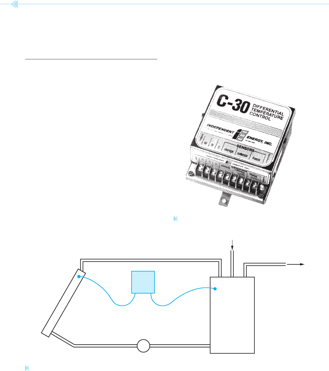
between them. A solar hot-water system is shown in
Figure 29–17. A solar collector is used to heat the
water. A storage tank stores the heated water and
acts as a heat exchanger for the domestic hot water
for the home. The system is controlled by the differ-
ential thermostat. When the temperature of the col-
lector becomes greater than the temperature of the
water in the storage tank by so many degrees, the
thermostat activates the pump motor. The pump
motor circulates water from the storage tank to the
collector, and from the collector back to the tank.
When the temperature of the collector is within a
certain amount of the water temperature, the ther-
mostat turns the pump off. In this way, water is cir-
culated through the collector only when the collector
is at a higher temperature than the stored water.
Figure 29–16
Differential thermostat. (Courtesy of Independent Energy Corp.)
Figure 29–17
Solar hot-water system controlled by a differential thermostat.
(Source: Delmar/Cengage Learning)
PUMP
TEMP.
SENSOR
SOLAR
COLLECT
OR
TEMP.
SENSOR
STORAGE
T
ANK
DOMESTIC HOT WATER
DIFF.
THERM.
A common setting for the differential thermostat
is 20 and 5. This means that the thermostat will
turn the pump on when the collector is 20 degrees
hotter than the stored water, and turn the pump off
when the collector is only 5 degrees hotter than the
stored water.

UNIT 29 The Thermostat 291
E Emergency heat relay on heat pumps
G Fan
K1 Switched side, Second source—Class 2
power
K2 Unswitched side, Second source—Class 2
power
L Indicator circuits or system monitors
O Damper (cooling) or reversing valve on heat
pump (cooling)
R Switched side, Class 2 power (single
source)
RC Switched side, Class 2 power, Cooling side
RH Switched side, Class 2 power, Heating side
T Outdoor thermostat
TT One side, Class 2 circuit-switch—Heat
TT Other side, Class 2 circuit-switch—Heat
W Heating
W1 1st Stage heating
W2 2nd Stage heating
W3 3rd Stage heating
X Lockout reset
Y Cooling
Y1 1st Stage cooling
Y2 2nd Stage cooling
Y3 3rd Stage cooling
NOTE:
Class 2 power sources are generally low
voltage and low power. They are not capable of
supplying enough power to create a re hazard or
a shock hazard.
Some manufacturers do not use the letters R,
G, Y, and W, but use letters V, F, C, and H. The V
terminal stands for voltage and is the same as the R
terminal. The F terminal stands for “fan” and is the
same as the G terminal. Terminal C stands for “com-
pressor” and is the same as the Y terminal, and the
H stands for “heat” and corresponds to the W ter-
minal. A chart illustrating the thermostat terminal
identi cation for different manufacturers is shown
in Figure 29–20.
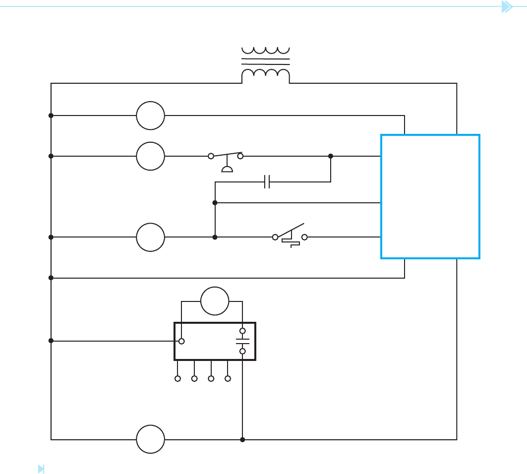
TESTING THE THERMOSTAT
It is possible to perform a simple test to deter-
mine if a problem exists in a thermostat. A jumper
wire is used to bypass parts of the thermostat. A
basic heating and cooling thermostat is shown in
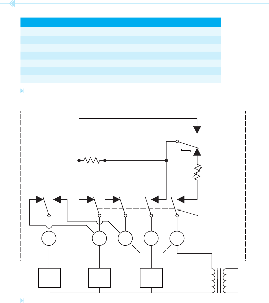
Figure 29–21. To perform the test, use a jumper
Some differential thermostats provide extra fea-
tures, such as antifreeze protection. Antifreeze
protection turns the pump on and circulates warm
water through the collector when its temperature is
near freezing. This does cool the warmed water, but
cooling the water is generally preferred to damaging
the collector. Some solar systems used a separate
water supply for the collector. These systems use a
mixture of antifreeze and water in the collector loop
to avoid freezing problems.
THERMOSTAT TERMINAL
IDENTIFICATION
Thermostats generally contain letters that are used
to identify the terminal connections. The most com-
mon letters are R, G, Y, W, B, and O. The letters
stand for common colors of thermostat wire.
R ⫽ Red
G ⫽ Green
Y ⫽ Yellow
W ⫽ White
B ⫽ Blue or Black
O ⫽ Orange
The B and O terminals are seldom used. The B terminal
connects to a heating damper and the O terminal
connects to a cooling damper. The other terminals con-
nect as follows:
R – One side of the control transformer (generally
24 volts)
G – Fan relay
Y – Compressor relay
W – Heating relay
Some heating/cooling thermostats use R
C
and R
H
instead of R. When these thermostats are used for
both heating and cooling, terminals R
C
and R
H
are
connected with a jumper, Figure 29–18.
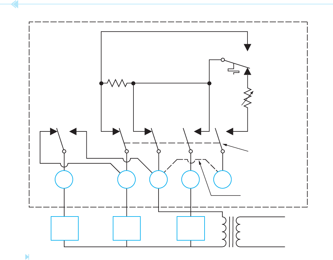
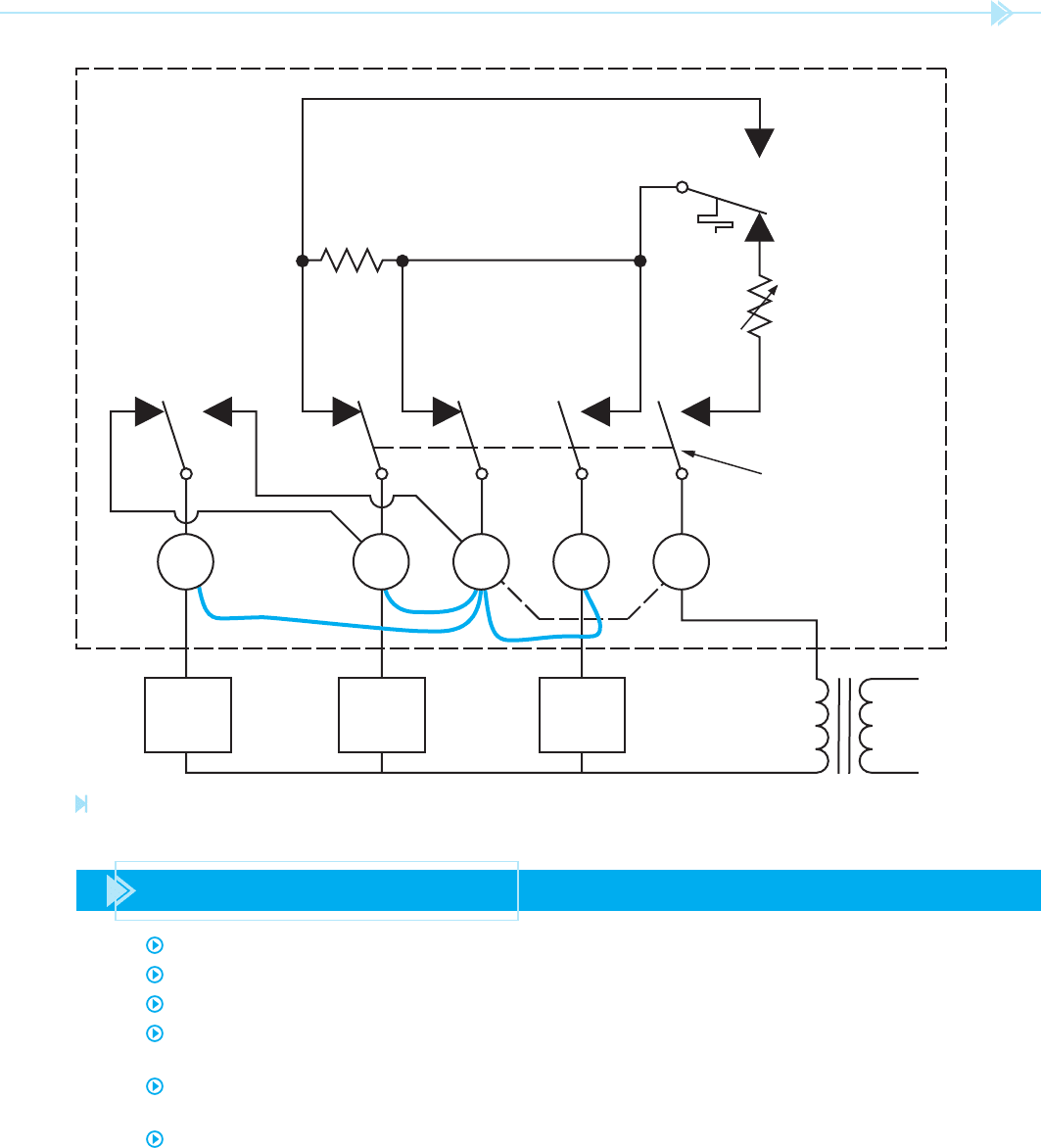
Heat pump thermostats generally contain ter-
minals not found on common heating/cooling
thermostats. Figure 29–19 illustrates the terminal
connections for a common heat pump thermostat.
A listing of thermostat terminals and their mean-
ings follows:
A General purpose (could be anything)
B Damper (heating) or Reversing solenoid on
heat pumps (heating)
C Unswitched side, Class 2 power
DF Defrost
292 SECTION 5 Control Components
is made from one of the R terminals and the Y
terminal, the compressor relay should energize,
and when connection is made from one of the
R terminals and the G terminal, the fan relay
should energize.
wire to make connection from the power input
terminal, R
C
or R
H
to the G, Y, and W terminals one
at a time, Figure 29–22. When connection is made
from one of the R terminals and the W terminal, the
heating relay should energize. When connection
R
H
HEAT/COOL
SWITCH
COOL
COOLING
ANTICIPATOR
AUTO ON
FAN
HEAT
ANTICIPATOR
HEAT
WR
C
Y
G
HEAT
RELAY
COMP.
RELAY
FAN
RELAY
JUMPER
TRANSFORMER
Figure 29–18
Thermostat terminal identifi cation for a common heating/cooling thermostat. (Source: Delmar/Cengage Learning)
UNIT 29 The Thermostat 293
OUTSIDE TEMPERATURE
FR
HIGH PRESSURE
TRANSFORMER
RG
BX
Y
E
W
2
CC
HR
CR
CONTROLS
REVERSING VALVE
AIR
TEMPERA-
TURE
COIL
TEMPERA-
TURE
THERMOSTAT
DFC
DR
Figure 29–19
Typical thermostat connection for a heat pump. (Source: Delmar/Cengage Learning)
294 SECTION 5 Control Components
MANUFACTURER TYPE COMMON COOLING HEATING FAN
Cam-Stat T17 R Y W
G
Cont. Corp. 360 R Y W G
General T91 V C H F&G
General T199 R Y W G
Honeywell T834 R Y W G
Honeywell T87 R Y W G
White-Rogers IF56 R Y W G
Figure 29–20
Typical thermostat markings. (Source: Delmar/Cengage Learning)
R
H
HEAT/COOL
SWITCH
COOL
COOLING
ANTICIPATOR
AUTO ON
FAN
HEAT
ANTICIPATOR
HEAT
WR
C
YG
HEAT
RELAY
COMP.
RELAY
FAN
RELAY
Figure 29–21
Basic heating and cooling thermostat.
(Source: Delmar/Cengage Learning)
UNIT 29 The Thermostat 295
R
H
HEAT/COOL
SWITCH
COOL
COOLING
ANTICIPATOR
AUTO ON
FAN
HEAT
ANTICIPATOR
HEAT
HEAT
RELAY
COMP.
RELAY
FAN
RELAY
WR
C
YG
Figure 29–22
Testing a thermostat. (Source: Delmar/Cengage Learning)
SUMMARY
Thermostats are temperature-sensitive switches.
Most thermostats are intended to be used on low voltage control systems.
A bimetal strip is often used to sense the temperature.
Bimetal strips are generally bent in a spiral and resemble a clock spring. This is done to
permit a longer length to t into a small area.
Contact thermostats have one stationary contact and one movable contact. The movable
contact is attached to the bimetal strip.
Contact-type thermostats use a small permanent magnet to provide a snap action when
the contact opens or closes.
296 SECTION 5 Control Components
Mercury-type thermostats operate by enclosing a pool of mercury inside a glass envelope.
The glass envelope is attached to a bimetal strip.
The weight of the mercury provides the snap action for the contacts when they open
or close.
Some thermostats are designed to be used as both a heating and cooling thermostat.
The heat anticipator is a small resistive heater located near the bimetal strip. Its purpose
is to open the contacts before the temperature actually reaches the thermostat setting.
The cooling anticipator is a small resistive heater located near the bimetal strip of an
air conditioning thermostat. It operates when the thermostat contacts are open and
causes them to close before the ambient temperature becomes high enough to close
the contacts.
Some thermostats contain a fan switch, which permits the blower fan to be operated
independently of the heating or cooling system.
Line voltage thermostats are made with large contacts and can be used to connect a load
to the line.
Programmable thermostats contain more than one set of contacts and can be set to
operate at different temperature settings at different times.
Staging thermostats contain more than one set of contacts and are generally used with
heat-pump systems. The rst set of contacts is used to turn on the compressor and the
second set of contacts is used to turn on the strip heaters.
KEY TERMS
antifreeze protection
cooling anticipator
contact
differential
thermostat
fan switch
heat anticipator
line voltage thermostat
programmable
thermostat
staging thermostat
thermostats
REVIEW QUESTIONS
1. What is a thermostat?
2. What is the advantage of an open-contact thermostat?
3. What is the disadvantage of an open-contact thermostat?
4. What is the advantage of a mercury thermostat?
5. What is used to provide a snap action for the contacts in an open-contact type
of thermostat?
6. What is used to provide a snap action for the mercury thermostat?

UNIT 29 The Thermostat 297
7. What method of sensing temperature is often used with line voltage thermostats?
8. What is a programmable thermostat?
9. What is the advantage of the programmable thermostat?
10. What is a differential thermostat?
11. What are differential thermostats generally used to control?
12. What is antifreeze protection in reference to a differential thermostat?
13. What is the advantage of a low-voltage thermostat over a line voltage thermostat?
14. What is the purpose of the heat anticipator?
15. How is the setting of the heat anticipator generally determined?
16. To what does the G terminal on a typical heating/cooling thermostat connect?
17. Some thermostats contain terminals marked R
C
and R
H
. What must be done if this
thermostat is used for both heating and cooling?
18. A thermostat has a terminal marked C. To what does this terminal connect?

High- and low-pressure switches are used to sense
the amount of pressure in an air conditioning and
refrigeration system. They are used to disconnect
the compressor from the power line if the pressure
should become too high or too low. Most of the pres-
sure switches used for air conditioning are operated
by a
bellows. A tube is attached to one end of the
bellows and the other end is connected to the dis-
charge or suction side of the compressor, depending
on which type of pressure switch is used.
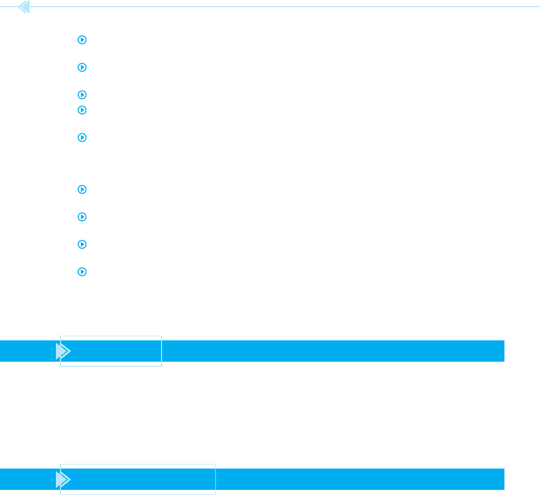
THE HIGH-PRESSURE SWITCH
Figure 30–1 illustrates the operation of a high-
pressure switch. The bellows is connected to
the discharge side of the compressor via the tube.
As the pressure of the system increases, the bellows
298
OBJECTIVES
After studying this unit the student should
be able to:
Describe the operation of high-
pressure switches
Describe the operation of low-pressure
switches
Make connection of a high-pressure
switch
Make connection of a low-pressure
switch
UNIT 30
Pressure
Switches
UNIT 30 Pressure Switches 299
expands. The bellows is used to activate a spring-
loaded normally closed switch. If the pressure
should become too great, the bellows will expand
far enough to open the switch. The normally closed
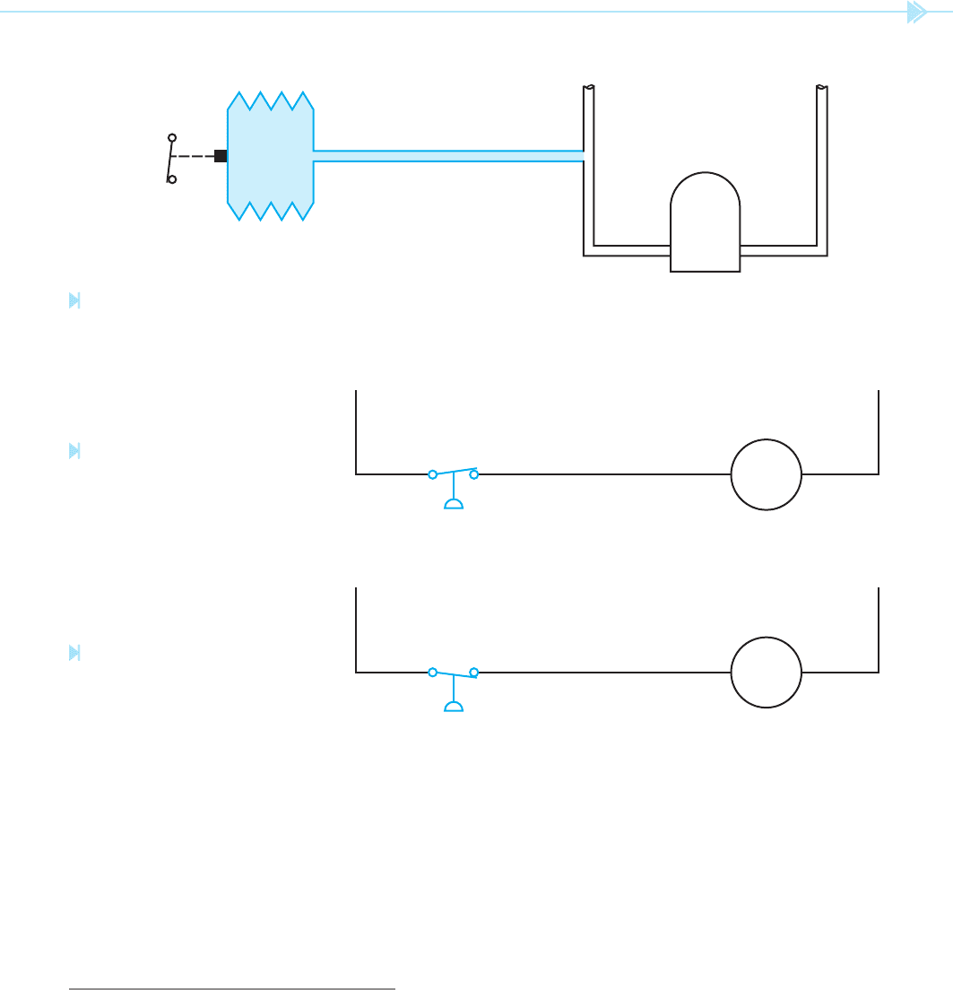
pressure switch is connected in series with the com-
pressor circuit shown in Figure 30–2. The pressure
switch may be connected in series with the compres-
sor, or in series with the compressor control relay,
depending on the type of control circuit.
THE LOW-PRESSURE SWITCH
The low-pressure switch is very similar in
construction to the high-pressure switch. The
low-pressure switch, however, is connected to the
BELLOWS
DISCHARGE
SUCTION
COMP.
SNAP
ACTION
SWITCH
Figure 30–1
Pressure switch connected to sense high pressure.
(Source: Delmar/Cengage Learning)
Figure 30–2
The pressure switch opens when
the pressure becomes too high.
(Source: Delmar/Cengage Learning)
L
1
L
2
COMP.
Figure 30–3
The pressure switch opens when
the pressure becomes too low.
(Source: Delmar/Cengage Learning)
L
1
L
2
COMP.
low-pressure or suction side of the compressor.
The low-pressure switch is used to disconnect the
compressor from the circuit if the pressure on the
suction side should become too low. Figure 30–3
illustrates this type of circuit. The low-pressure
switch is a normally open held-closed switch. The
switch is held in the closed position by the pres-
sure of the system. If the pressure should drop low
enough, the switch will open and disconnect the
compressor from the circuit. As with the high-
pressure switch, the low-pressure switch can be
used to disconnect the compressor from the line
or disconnect the compressor relay, depending on
the type of control circuit. A low-pressure switch is
shown in Figure 30–4.