Stephen L. Herman, Bennie Sparkman. Electricity and Controls for HVAC-R (6th edition)
Подождите немного. Документ загружается.

320 SECTION 5 Control Components
KEY TERMS
control contacts
current-limiting
resistor
differential pressure
switch
oil-pressure failure
switch
time-delay circuit
REVIEW QUESTIONS
1. How can the actual amount of useful oil pressure in a compressor be found?
2. What is the function of the current-limiting resistor?
3. Why is the current-limiting resistor center tapped?
4. Does a high enough oil pressure open the differential pressure switch contacts or
close them?
5. What is the function of the heater?
6. Explain the sequence of events that take place if the oil pressure does not become great
enough to disconnect the heater circuit.
7. What is the cut-in point?
8. What is the cut-out point?
9. Is the timer circuit connected in series with the motor starter coil?
10. Are the overload contacts connected in series with the motor starter coil?

321
A solenoid valve is an electrically operated valve.
These valves are used to control the ow of gases
or liquids. They range in complexity from a simple
on-off valve to 4-way reversing valves used on heat-
pump systems. A simple plunger-type of solenoid
valve is shown in Figure 35–1. This type of valve
is often used to control the ow of gas or liquid in
an air conditioning system. The plunger of the sole-
noid is used to lift the valve off its seat. The valve is
held closed by a spring when it is in its normal or
deenergized position. When the coil is energized, the
plunger lifts the valve off the seat and liquid or gas
is permitted to ow from the
inlet to the outlet.
When the coil is deenergized, the spring returns the
valve to the seat and stops the
ow of liquid or gas.
Notice that the valve is marked with an inlet and
outlet side. The inlet is connected to the side of the
system with the highest pressure. In this way, the
UNIT 35
Solenoid
Valves
OBJECTIVES
After studying this unit the student should
be able to:
Defi ne a solenoid
Properly connect the inlet and outlet of
a solenoid valve
Describe the operation of a 4-way, or
reversing, valve
Make the proper electrical connections
for a solenoid valve
322 SECTION 5 Control Components
pressure of the system is used to help keep the valve
closed. If the valve should be reversed and pressure
applied to the outlet side, the pressure of the system
could be enough to overcome the tension of the
spring and lift the plunger off the seat. This would
cause the valve to leak.
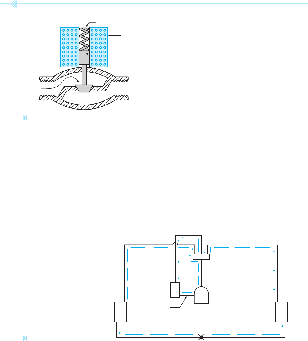
THE REVERSING VALVE
A very common solenoid valve used in the air
conditioning eld is the 4-way valve or revers-
ing valve. Reversing valves are used to change
the direction of ow of refrigerant in a heat-pump
system. Figure 35–2 shows the direction of refriger-
ant ow when the heat-pump unit is in the cooling
cycle. Notice that the high-pressure gas leaving
the compressor enters the reversing valve. It is
then directed to the outside coil being used as the
condenser during the cooling cycle. Liquid refriger-
ant ows from the outside coil to the metering
device where it is changed to a low-pressure liq-
uid. The low-pressure liquid then enters the inside
coil where it attracts heat from the inside air and
changes to a gas. It then ows to the reversing
valve. The reversing valve directs the ow to the
accumulator and back to the compressor.
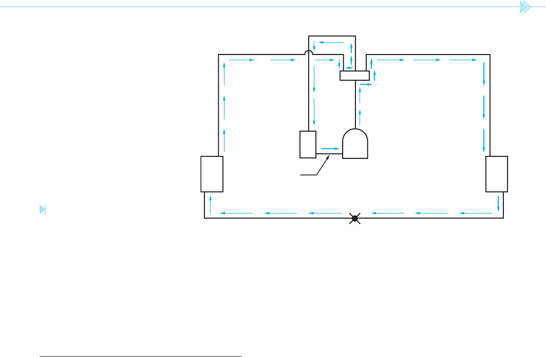
If the unit is now to be used for heating, the ow
of refrigerant must be reversed through the system,
Figure 35–3. Notice that the ow of hot, high-
pressure gas is still from the discharge side of the
compressor to the reversing valve. In this example,
however, the ow of high-pressure gas is directed
to the inside coil, which is now being used as the
condenser. Liquid refrigerant leaves the inside coil
and ows to the metering valve. The refrigerant
is changed into a low-pressure liquid after going
through the metering valve and owing to the out-
side coil. Heat is then added to the liquid from the
surrounding outside air. The gas then ows to
the reversing valve, the accumulator, and back to
the suction line of the compressor.
INLET OUTLET
PLUNGER
COIL
SPRING
Figure 35–1
Solenoid valve. (Source: Delmar/Cengage Learning)
SUCTION
LINE
COMPRESSOR
ACCUMULATOR
OUTSIDE
COIL
INSIDE
COIL
METERING
DEVICE
DISCHARGE
LINE
REVERSING
VALVE
Figure 35–2
Refrigerant fl ow during the
cooling cycle. (Source: Delmar/Cengage Learning)
UNIT 35 Solenoid Valves 323
Notice in both examples that the direction of
refrigerant ow from and to the compressor is the
same. The reversing valve was used to change the
direction of ow.
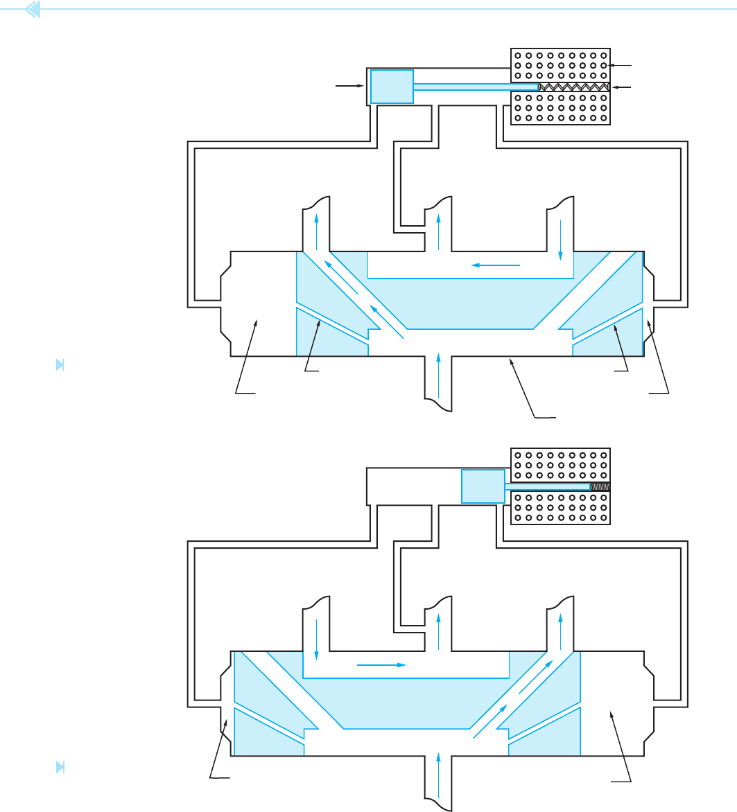
REVERSING VALVE OPERATION
The 4-way reversing valve is actually two valves that
operate together. There is a main valve that actually
controls the ow of refrigerant in the system, and a
pilot valve that controls the operation of the main
valve, Figure 35–4. The force needed to operate the
main valve is provided by the compressor. The valve
shown in Figure 35–4 has a sliding valve body that
is used to control the ow of refrigerant through the
system. In the illustration shown, the system is being
used in the cooling cycle. Notice that on each side of
the valve there is a small passage called an ori ce.
The ori ce provides a path for a very small amount
of refrigerant to ow. Notice also that there is a small
capillary tube connected from each end of the valve
body to the pilot valve and a third capillary tube
connected from the pilot valve to the suction line of
the compressor. In the position shown, the plunger
of the pilot valve is blocking the capillary from the
left side of the main valve body. The capillary tube
connected to the right side of the main valve is con-
nected to the suction side of the compressor through
the pilot valve. With the plunger of the pilot valve in
this position, a high pressure is formed on the left side
of the main valve and a low pressure is formed on
the right side. The high pressure created on the left
side of the main valve forces the main valve to slide
to the right. With the main valve in this position, the
discharge line of the compressor is connected to
the outside coil and the inside coil is connected to the
suction side of the compressor.
If the
solenoid coil is energized, the plunger of
the pilot valve will change to the position shown in
Figure 35–5. The plunger now blocks the capillary
tube connected to the right side of the main valve
body. The capillary tube connected on the left side
of the main valve is now connected to the suction
line of the compressor through the pilot valve. This
causes a high pressure to be created on the right
side of the main valve and a low pressure on the
left side. The high pressure forces the main valve
to slide to the left. When the reversing valve is in
this position, the discharge side of the compressor
is connected to the inside coil and the suction line
is connected to the outside coil. The unit is now in
the heating cycle.
SUCTION
LINE
COMPRESSOR
ACCUMULATOR
OUTSIDE
COIL
INSIDE
COIL
METERING
DEVICE
DISCHARGE
LINE
REVERSING
VALVE
Figure 35–3
Refrigerant fl ow during the
heating cycle. (Source: Delmar/
Cengage Learning)
324 SECTION 5 Control Components
HIGH PRESSURE
ORIFICE
LOW PRESSURE
MAIN VALVE
ORIFICE
TO OUTSIDE COIL
TO
COMPRESSOR
SUCTION
TO COMPRESSOR
DISCHARGE
TO INSIDE COIL
COIL
SPRING
PILOT VALVE
Figure 35–4
Reversing valve
set for the
cooling cycle.
(Source: Delmar/Cengage
Learning)
LOW PRESSURE
HIGH PRESSURE
TO OUTSIDE COIL
TO
COMPRESSOR
SUCTION
TO COMPRESSOR
DISCHARGE
TO INSIDE COIL
Figure 35–5
Reversing valve
set for the
heating cycle.
(Source: Delmar/Cengage
Learning)
UNIT 35 Solenoid Valves 325
SUMMARY
A solenoid valve is an electrically operated valve.
The inlet and outlet side of a valve should never be reversed.
Four-way valves are used to reverse the ow of refrigerant in a heat pump system.
Reversing valves are actually two valves that operate together.
The solenoid coil of a 4-way valve actually operates a pilot valve that is used to operate the
main valve.
The force needed to operate the main valve is provided by the compressor.
The valve illustrated in this example shows
the valve is in the cooling cycle when the sole-
noid is deenergized and in the heating cycle when
energized. This has been standard for many years
for heat-pump systems. Now, however, some
manufacturers are reversing this procedure. Some
reversing valves are made in such a manner that
when the valve is deenergized the unit is in the
heating cycle. This was done so that valve failure
would result in the unit being in the heating cycle.
It is felt that heat is necessary to life while air con-
ditioning is not. A 4-way reversing valve is shown
in Figure 35–6.
Figure 35–6
Reversing valve. (Source: Delmar/Cengage Learning)
4-way valve
inlet
metering device
ori ce
outlet
pilot valve
reversing valve
solenoid coil
solenoid valve
KEY TERMS

326 SECTION 5 Control Components
REVIEW QUESTIONS
1. What is a solenoid valve?
2. Why is it important not to reverse the connection of the inlet and outlet side of a
solenoid valve?
3. What is used to cause the plunger to close when the solenoid coil is deenergized?
4. What is the function of a 4-way reversing valve?
5. What is the function of the pilot valve?
6. What is the function of the main valve?
7. What is actually used to change the position of the main valve from one setting
to another?

327
Short cycling is a condition that occurs when the
compressor is restarted immediately after it has been
turned off. This causes the compressor to restart
against a high head pressure. Trying to restart a
compressor in this manner can cause damage to
the compressor, motor winding, or at the very least,
open a circuit breaker or overload relay. After a
compressor has been turned off, enough time should
be permitted to pass to allow the pressure in the
system to equalize before it is restarted.
CAUSES OF SHORT CYCLING
Short cycling can be caused by several situations.
For example, a loose thermostat wire can cause a
bad connection that will cause the compressor to
alternately start and stop. A momentary interrup-
tion of the power line can cause the compressor to
UNIT 36
The Short-
Cycle Timer
OBJECTIVES
After studying this unit the student should
be able to:
Defi ne the condition known as short
cycling
List reasons that short cycling occurs
Describe the construction of a
short-cycle timer
Describe the circuit operation of a
short-cycle timer
Connect a short-cycle timer in the
circuit

328 SECTION 5 Control Components
stop and then restart when power is restored. People
can also cause short cycling. Assume, for example,
that the air conditioning system is in operation.
Now assume that someone changes the thermostat
setting and causes the thermostat contact to open
and stop the compressor. Now assume that the
person changes his mind and again changes the
thermostat so that the compressor tries to restart.
Regardless of the reason or causes of short cycling,
it should be avoided whenever possible.
THE SHORT-CYCLING TIMER
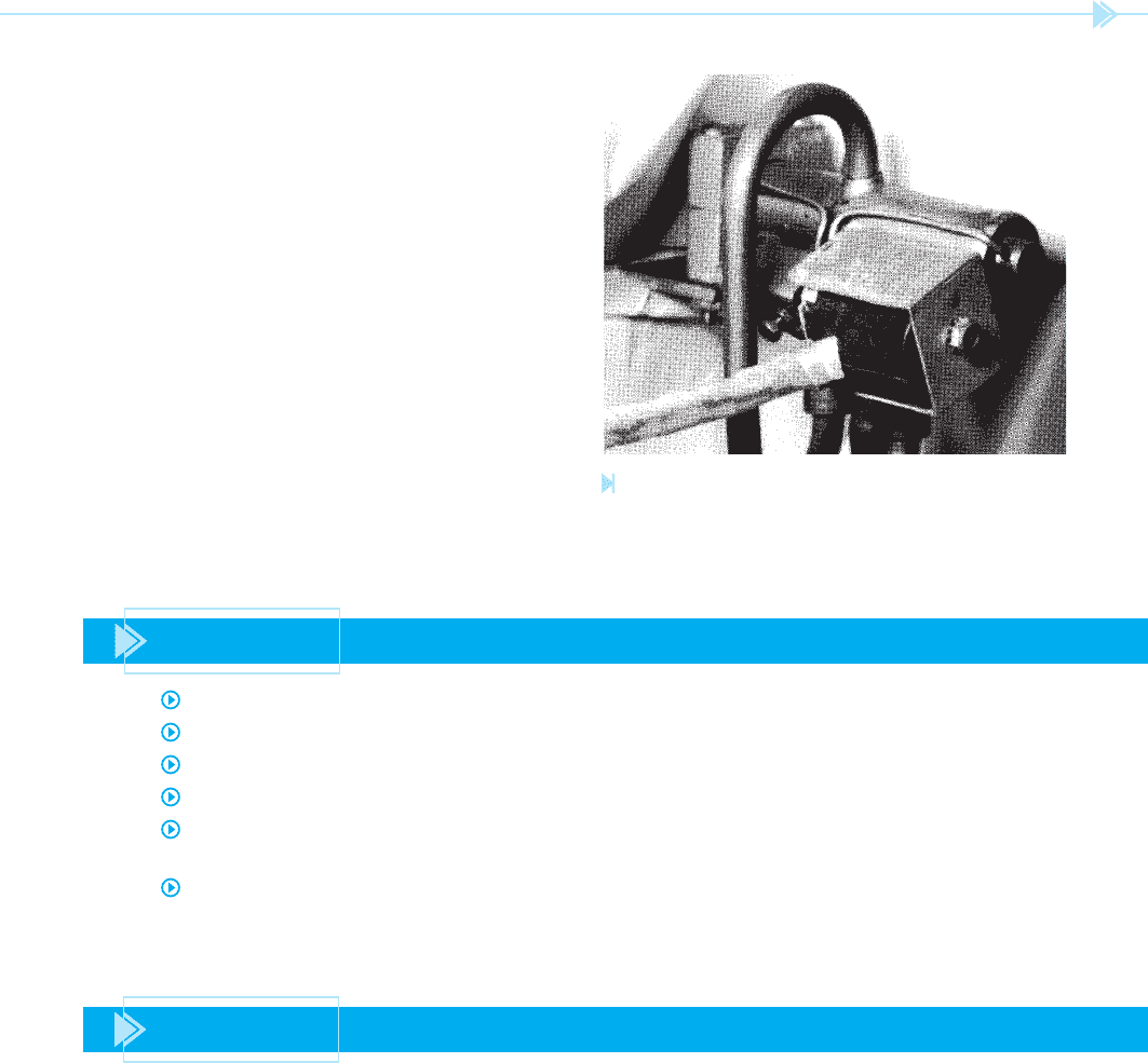
The short-cycling timer is a cam-operated,
motor driven, on-delay timer. A photograph of a
short-cycling timer is shown in Figure 36–1. This
timer is used in conjunction with a relay generally
referred to as a holding relay. The timer contains a
set of double-pole double-throw contacts (DPDT).
A basic schematic of a short-cycling timer circuit is
shown in Figure 36–2. Notice the two sets of double-
throw contacts labeled A and B. The dashed line
L
2
L
1
HR
2
B
2
B
TM
TIMER MOTOR
B
1
A
2
A
C
COMPRESSOR
CONTACTOR
CR
24 V
240 V
CONTROL
TRANSFORMER
CONTROL
RELAY
THERMOSTAT
HR
HOLDING RELAY
A
1
HR
1
CR
Figure 36–1
Short-cycling timer. (Source: Delmar/Cengage Learning)
Figure 36–2
Basic schematic of a short-cycle
timer circuit. (Source: Delmar/
Cengage Learning)
UNIT 36 The Short- Cycle Timer 329
between the contacts indicates mechanical connec-
tion so that they operate together. Notice also the
holding relay labeled HR. The circuit is controlled by
the operation of the thermostat.
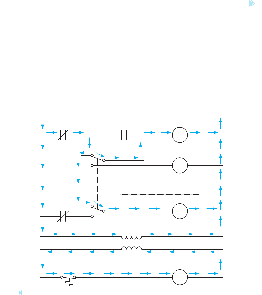
CIRCUIT OPERATION
To understand the operation of this circuit, refer to
the schematic shown in Figure 36–3. The arrows
indicate the paths for current ow. Notice there
is a path from line L1 through the primary of the
control transformer and back to L2. This provides
24 volts for the operation of the control circuit.
When the thermostat contacts close, a circuit is
provided through the coil of the control relay (CR).
This causes contact CR to close and provides a cur-
rent ow path to the short-cycle timer. Notice there
are two paths of current ow at the timer. The cur-
rent enters the A1 terminal and ows to the B1 con-
tact terminal. The current can then ow through
the contact to terminal B and then to the
timer
motor. There is also a current path from terminal
A1 to A. The current can then
ow from A to the
holding relay (HR).
The holding relay energizes and changes both HR
contacts as shown in Figure 36–4. The now closed
HR 1 contact is used as a holding contact. Notice
that current is also
owing through the timer motor.
The timer motor is geared to permit a delay of about
3 minutes before the contacts change position.
A
1
A
2
A
B
1
B
B
2
L
1
L
2
CR HR
1
HR
C
TM
CR
HR
2
THERMOSTAT
Figure 36–3
The thermostat energizes the control relay. (Source: Delmar/Cengage Learning)