Stephen L. Herman, Bennie Sparkman. Electricity and Controls for HVAC-R (6th edition)
Подождите немного. Документ загружается.

340 SECTION 5 Control Components
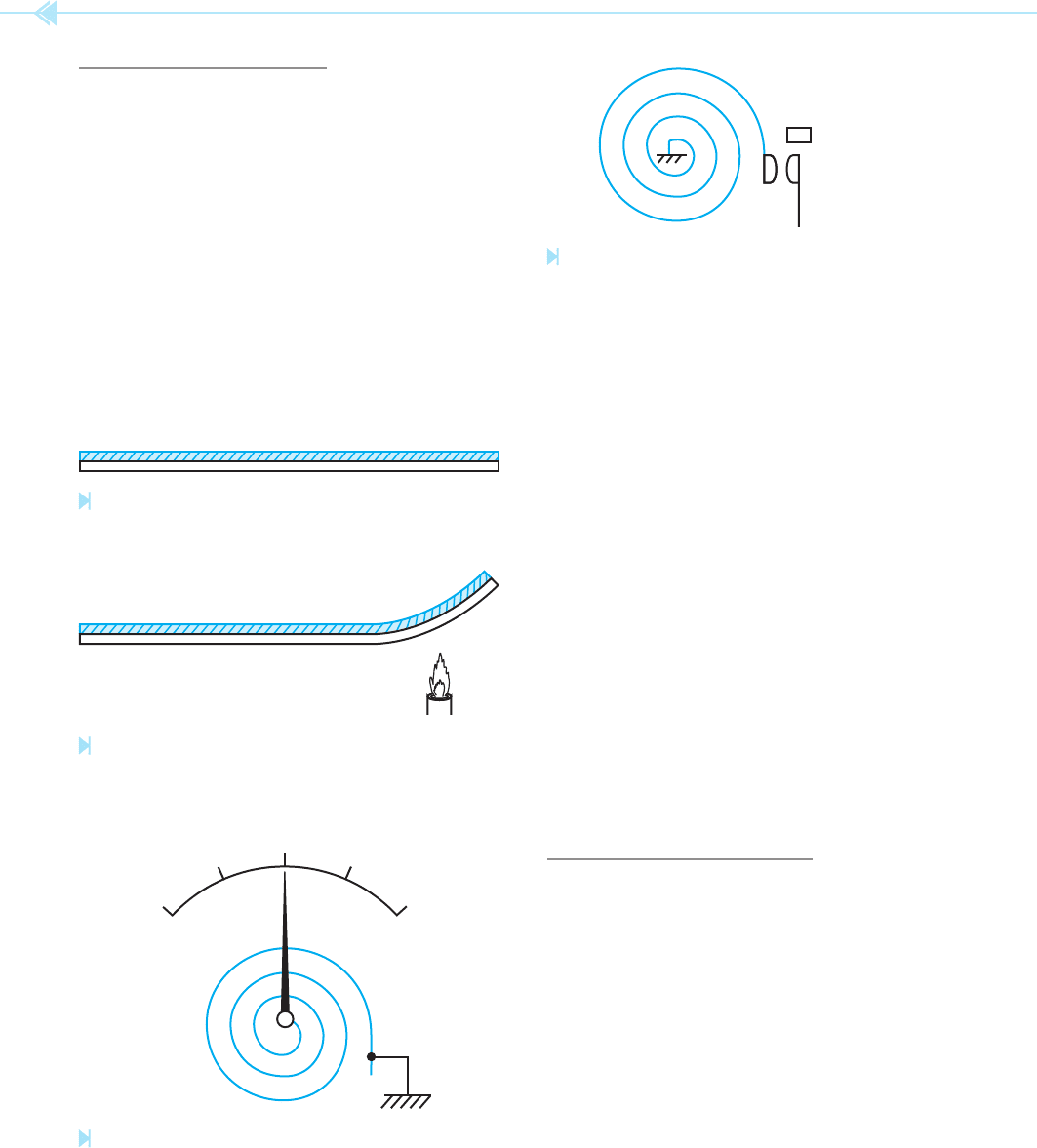
will be produced by a change of temperature. If one
end of the strip is mechanically held, and a pointer
is attached to the center of the spiral, a change
in temperature will cause the pointer to rotate. If
a calibrated scale is placed behind the pointer, it
becomes a thermometer. If the center of the spiral
is held, and a contact is attached to the end of the
bimetal strip, it becomes a thermostat. As stated
previously, electrical contacts cannot be permitted
to open or close slowly. This type of thermostat uses
a small permanent magnet to provide a snap action
for the contact, Figure 37–7. When the moving
contact reaches a point that is close to the station-
ary contact, the magnet attracts the metal strip and
causes a sudden closing of the contacts. When the
bimetal strip cools, it attempts to pull itself away
from the magnet. When the force of the bimetal strip
becomes strong enough, it overcomes the force of
the magnet and the contacts snap open. This type
of thermostat is inexpensive and has been used in
homes for many years.
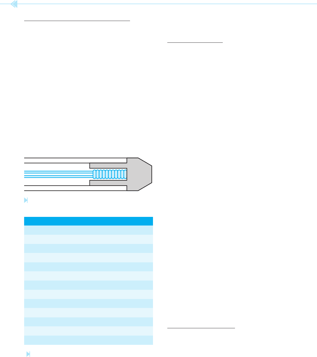
THE THERMOCOUPLE
The thermocouple is made by joining two dis-
similar metals together at one end. When the joined
end of the thermocouple is heated, a voltage is pro-
duced at the opposite end, Figure 37–8. The amount
of voltage produced is proportional to:
1. The types of metals used to produce the ther-
mocouple.
2. The difference in temperature of the two
junctions.
The chart in Figure 37–9 shows common types of
thermocouples. The metals the thermocouples are
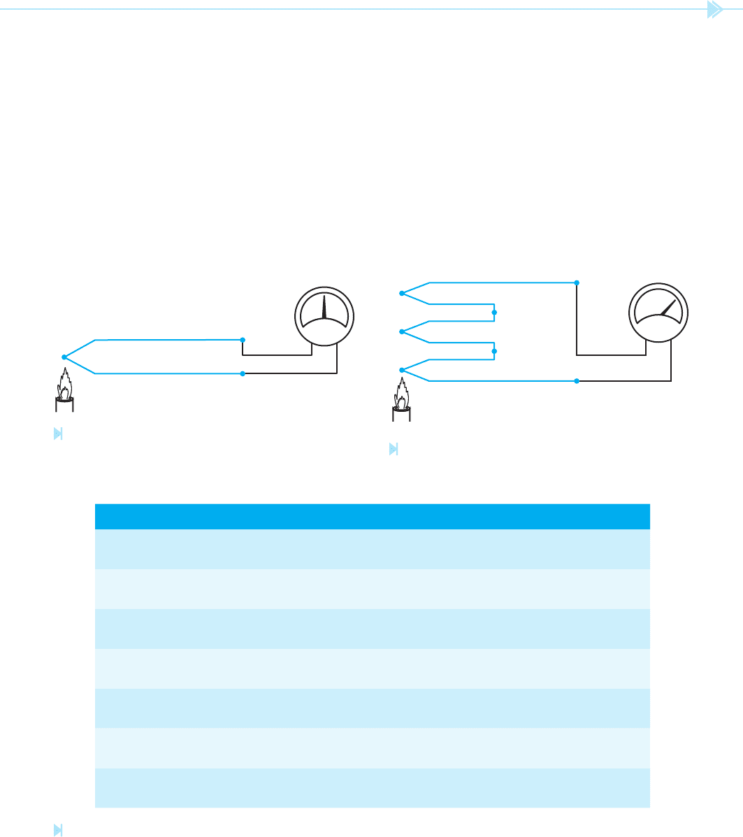
THE BIMETAL STRIP
The bimetal strip is another device that operates by
the expansion of metal. It is probably the most com-
mon heat-sensing device used in the production of
thermometers and thermostats. The bimetal strip
is made by bonding two dissimilar types of metal
together, Figure 37–4. Because these metals are
not alike, they have different expansion rates. This
difference causes the strip to bend or wrap when
heated, Figure 37–5.
The bimetal strip is often formed into a spiral
shape as shown in Figure 37–6. The spiral permits
a longer bimetal strip to be used in a small space.
The longer the strip is, the more movement that
Figure 37–4
A bimetal strip. (Source: Delmar/Cengage Learning)
Figure 37–5
A bimetal strip warps with a change of temperature.
(Source: Delmar/Cengage Learning)
50
25
0
75
100
Figure 37–6
A bimetal strip used as a thermometer.
(Source: Delmar/
Cengage Learning)
PERMANENT
MAGNET
Figure 37–7
A bimetal strip used to operate a set of contacts. (Source:
Delmar/Cengage Learning)
UNIT 37 Methods of Sensing Temperature 341
a voltage of about 7.9 millivolts. At a temperature
of –300 degrees, it produces a voltage of about
–7.5 millivolts. This indicates that at temperatures
below 32 degrees Fahrenheit the iron wire becomes
the negative lead and the constantan wire becomes
the positive-voltage lead.
Because thermocouples produce such low volt-
ages, they are often connected in series as shown
in Figure 37–10. This series connection permits the
voltages to add and produce a higher output volt-
age. This connection is known as a thermopile.
constructed from are shown as well as their normal
temperature range.
The amount of voltage produced by a thermo-
couple is small, generally on the order of millivolts
(1 millivolt ⫽ .001 volt). The polarity of the voltage
of a thermocouple is determined by the tempera-
ture. For example, a type “J” thermocouple produces
zero volts at about 32 degrees Fahrenheit. At tem-
peratures above 32 degrees, the iron wire is positive
and the constantan wire is negative. At a tempera-
ture of 300 degrees, this thermocouple will produce
Figure 37–8
A thermocouple produces a voltage when the two ends
are at different temperatures. (Source: Delmar/Cengage Learning)
TYPE MATERIAL DEGREES F DEGREES C
J Iron Constantan −328 to +32
+32 to +1432
−200 to 0
0 to 778
K Chromel Alumel −328 to +32
+32 to +2472
−200 to 0
0 to 1356
T Copper Constantan −328 to +32
+32 to +752
−200 to 0
0 to 400
E Chromal Constantan −328 to +32
+32 to +1832
−200 to 0
0 to 1000
R Platinum
13% Rhodium
Platinum +32 to +3232 0 to 1778
S Platinum
10% Rhodium
Platinum +32 to +3232 0 to 1778
B Platinum
30% Rhodium
Platinum
6% Rhodium
+992 to +3352 533 to 1800
Figure 37–9
Thermocouple chart. (Source: Delmar/Cengage Learning)
Figure 37–10
Thermocouple. (Source: Delmar/Cengage Learning)
342 SECTION 5 Control Components
RTD probe. The temperature is given in degrees
Celsius and resistance is given in ohms.
THERMISTORS
The term thermistor is derived from the words ther-
mal
and resistor. Thermistors are actually thermally
sensitive semiconductor devices. There are two
basic types of thermistors. One type has a
nega-
tive temperature coef cient
(NTC) and the
other has a
positive temperature coef cient
(PTC). A thermistor that has a negative tempera-
ture coef
cient will decrease its resistance as the
temperature increases. A thermistor that has a posi-
tive temperature coef cient will increase its resis-
tance as temperature increases. The NTC thermistor
is the most widely used.
Thermistors are highly nonlinear devices. For
this reason, they are dif cult to use for measuring
temperature. Devices that measure temperature
with a thermistor must be calibrated for the particu-
lar type of thermistor being used. If the thermistor is
ever replaced, it has to be an exact replacement or
the circuit will no longer operate correctly. Because
of their nonlinear characteristic, thermistors are
often used as set point detectors as opposed to actual
temperature measurement. A set point detector
is a device that activates some process or circuit
when the temperature reaches a certain level. For
example, assume a thermistor has been placed
inside the stator of a motor used to operate a com-
pressor. If the motor should become overheated, the
windings of the motor could be severely damaged or
destroyed. The thermistor can be used to detect the
temperature of the windings. When the resistance
of the thermistor falls to a certain level, NTC type,
a set of contacts connected in series with the motor
starter coil of the compressor, opens. When the com-
pressor motor starter deenergizes, the compressor is
disconnected from the power line. Thermistors can
be operated in temperatures that range from about
–100 to ⫹300 degrees Fahrenheit.
THE PN JUNCTION
Another device that has the ability to measure tem-
perature is the PN junction or diode. The diode
is becoming a very popular device for measuring
temperature because it is accurate and linear.
RESISTANCE TEMPERATURE
DETECTORS
The resistance temperature detector (RTD)
is made of platinum wire. The resistance of platinum
changes greatly with temperature. When platinum
is heated, its resistance increases at a very predictable
rate. This makes the RTD an ideal device for mea-
suring temperature very accurately. RTDs are used
to measure temperatures that range from –328 to
⫹1166 degrees Fahrenheit (–200 to ⫹630 degrees
Celsius). RTDs are made in different styles to perform
different functions. Figure 37–11 illustrates a typical
RTD used as a probe. A very small coil of platinum
wire is encased inside a copper tip. Copper is used to
provide good thermal contact. This permits the probe
to be very fast-acting. The chart in Figure 37–12
shows resistance versus temperature for a typical
Figure 37–11
Resistance temperature detector. (Source: Delmar/Cengage Learning)
DEGREES C RESISTANCE
0 100
50 119.39
100 138.5
150 157.32
200 175.84
250 194.08
300 212.03
350 229.69
400 247.06
450 264.16
500 280.93
550 297.44
600 313.65
Figure 37–12
Temperature and resistance for a typical RTD.
(Source: Delmar/Cengage Learning)
UNIT 37 Methods of Sensing Temperature 343
the transistor and the sensor diode. The value of R1
also determines the amount of current that will ow
through the diode. Diode D1 is a 5.1-volt zener diode
used to produce a constant voltage between the base
and emitter of the PNP transistor. Resistor R2 limits
the amount of current ow through the zener diode
and the base of the transistor. Diode D2 is a common
silicon diode. It is being used as the temperature sen-
sor for the circuit. If a digital voltmeter is connected
across the diode, a voltage drop between .8 and
0 volts can be seen. The amount of the voltage drop
is determined by the temperature of the diode.
If the diode is subjected to a lower temperature,
say by touching it with a piece of ice, it will be seen
that the voltage drop of the diode will increase. If the
temperature of the diode is increased by holding it
between two ngers or bringing a hot soldering iron
near it, its voltage drop will decrease. Notice that
the diode has a negative temperature coef cient.
As its temperature increases, its voltage drop
becomes less. The circuit shown in Figure 37–14
When a silicon diode is used as a temperature sen-
sor, a constant current is passed through the diode.
Figure 37–13 shows this type of circuit. In this
circuit, resistor R1 limits the current ow through
Figure 37–13
Constant current generator. (Source: Delmar/Cengage Learning)
+
1000 µf
C2
+
–
+
1000 µf
C1
120 VAC
12.6 VCT
R6
R3 D3
1K
R4
1K
R5
Q2
2N2907
D5
(REF. VOLTAGE)
1K
4.7K
R7
5K
4
3
2
6
7
741
D4
1K
R1
1K
R2
D2
1N4004
TEMP.
SENSOR
Q1
2N2907
D1
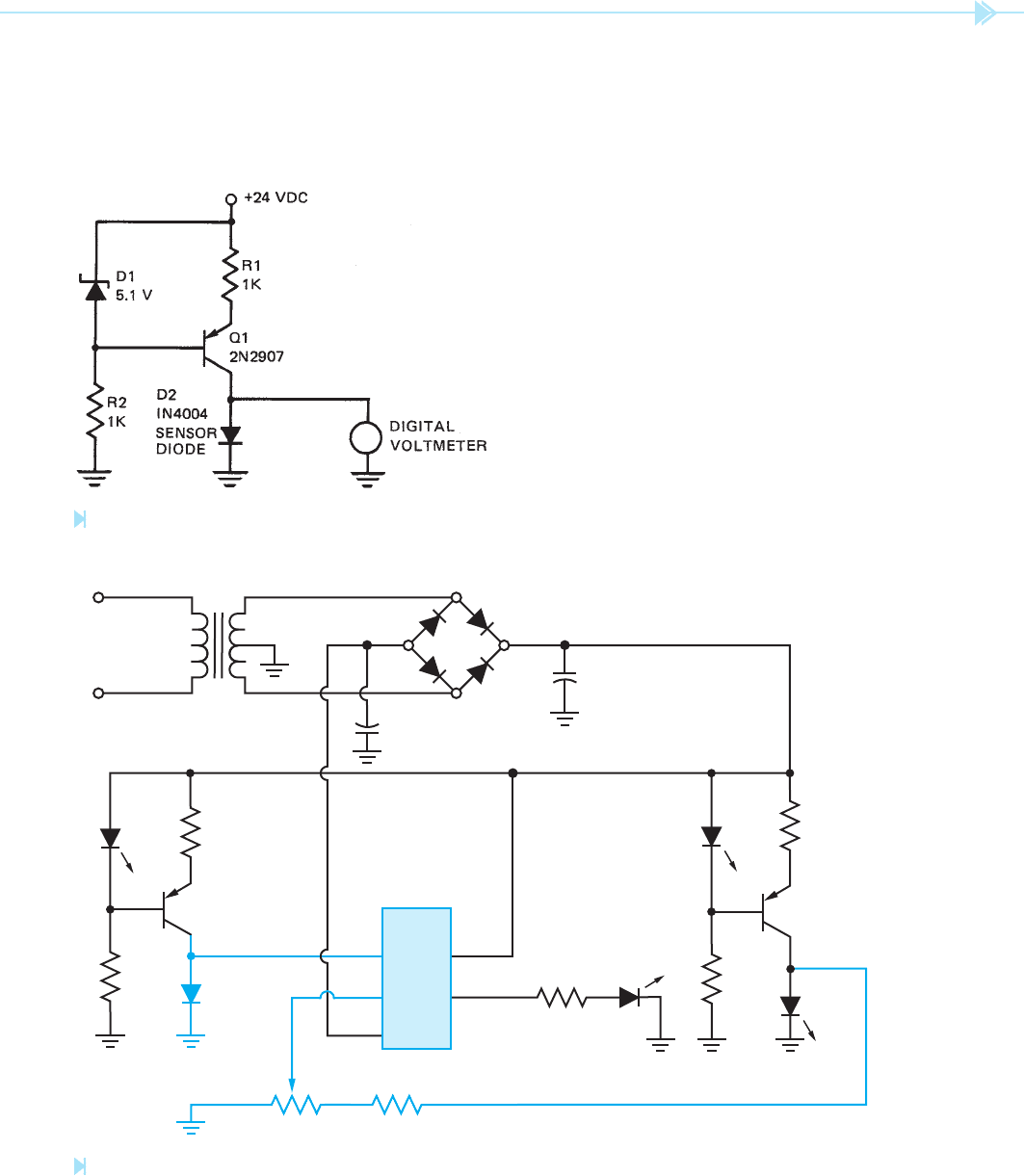
Figure 37–14
Set level detector for temperature. (Source: Delmar/Cengage Learning)

344 SECTION 5 Control Components
voltage applied to the noninverting input between
1 volt and 0. This is done to make adjustment of
the detector circuit easy. Because the voltage drop
of diode D2 will never be greater than .8 volts,
resistor R7 can adjust the entire range over which
the detector can operate.
Diode D3 is used as an output indicator. When
the output is low, D3 will be turned off. When the
output of the op amp goes high, D3 will be turned
on. Diode D3 is used only as an indicator in this
circuit. The output of the op amp could be used
to operate the input of a transistor or a solid-state
relay. The transistor or relay could be used to oper-
ate almost anything desired. Resistor R3 limits the
current ow through D3.
To understand the operation of this circuit,
assume that resistor R7 has been adjusted to a
point that the output of the op amp is off or low.
This means that the voltage applied to the invert-
ing input, pin 2, is more positive than the volt-
age set at pin 3. If the temperature of diode D2 is
increased, its voltage drop will decrease. When
the temperature of the sensor diode becomes high
enough, its voltage drop will be less than the volt-
age set at the noninverting input. When the volt-
age applied to pin 3 becomes more positive than the
voltage applied to pin 2, the output of the op amp
will go high or turn on. Adjustment of resistor R7
permits the detector to be used over a wide range of
temperatures.
EXPANSION DUE TO PRESSURE
Another common method of measuring tempera-
ture is by the increase of pressure of some chemi-
cals. Refrigerant, for example, increases pressure
as temperature increases. If a simple bellows is
connected to a line containing refrigerant, Fig-
ure 37–15, the bellows will expand as the pres-
sure inside the sealed system increases. When the
surrounding temperature decreases, the pressure
inside the system decreases, and the bellows con-
tracts. When the bellows is made to operate a set of
contacts, it is generally referred to as a
bellows-
type thermostat.
can be used as a set point detector. The operation of
the circuit is as follows.
A bridge recti
er and a center-tapped trans-
former are used to produce an above- and below-
ground power supply. If ground is considered as
zero volts, the positive output of the bridge will be
positive with respect to ground and the negative
output of the bridge will be negative with respect
to ground. Capacitors C1 and C2 are used to lter
the DC output voltage of the recti er. Notice that
capacitor C1 has its positive lead connected to
ground and C2 has its negative lead connected
to ground. The positive output of the recti er will
produce a voltage that is about ⫹9 volts compared
to ground, and the negative output will produce
a voltage that is about –9 volts compared to
ground.
Diode D1 is a light-emitting diode connected
in the forward direction. In this circuit, the LED
is used as a low-voltage zener diode. Because
the LED has a constant voltage drop of about
1.7 volts, it can be used to provide a constant volt-
age. Resistor R1 limits the current flow through
the diode and the sensor resistor. Resistor R2
limits current flow through the LED and the base
of the transistor. Notice this is the same constant
current generator circuit shown in Figure 37–13
with the exception of the LED’s being used as the
zener diode.
Transistor Q2, resistors R5 and R4, and LED D4
form another constant current generator circuit.
Notice this generator is connected to an LED, D5.
In this circuit, D5 is used to provide a low-voltage
reference source for the operational ampli er.
When a light-emitting diode is connected to a
constant current source, its voltage drop is very
stable. This makes it an ideal choice when a steady
reference voltage is needed. Resistors R6 and R7
are used to form a voltage divider. Resistor R5 is
a 5000-ohm variable resistor that has a voltage
drop across its entire resistance of about 1 volt.
The wiper tap of this resistor is connected to the
noninverting input of the 741. Because resistor
R5 has a voltage drop of only 1 volt across its resis-
tance, the full range of the wiper will adjust the
UNIT 37 Methods of Sensing Temperature 345
C
NO NC
BELLOWS
REFRIGERANT
Figure 37–15
Bellows contracts and expands with a change of refrigerant pressure. (Source: Delmar/Cengage Learning)
SUMMARY
A common method of sensing temperature is by the expansion of metal.
Two factors that determine the amount of expansion that will occur when metal is heated
are:
A. The type of metal used.
B. The temperature of the metal.
A common device that operates on the principle of expansion of metal is the mercury
thermometer.
A bimetal strip is constructed by bonding two types of metal together that expand at a dif-
ferent rate.
The sensitivity of a bimetal strip is proportional to its length.
Bimetal strips are often wound into a spiral to permit a longer strip to be used in a small
space.
Thermocouples produce a voltage when heated at one end.
Thermocouples are made by joining two dissimilar metals together at one end.
The amount of voltage produced by a thermocouple is determined by:
A. The types of metals used.
B. The difference in temperature of the two junctions.
Resistance temperature detectors (RTDs) are made of platinum wire.
The resistance of platinum changes at a very predictable rate as the temperature
changes.
Thermistors are devices that rapidly change their resistance with a change of tempera-
ture.
The resistance of a thermistor with a positive temperature coef cient will increase with an
increase of temperature.

346 SECTION 5 Control Components
The resistance of a thermistor with a negative temperature coef cient will decrease with
an increase of temperature.
Because of thermistors’ ability to rapidly change resistance with a change of temperature,
they are generally used as temperature-sensitive switches.
A PN junction can be used to sense temperature by passing a constant current through it
and detecting the voltage drop across the junction.
When a constant current is passed through a PN junction, its voltage drop is proportional
to the temperature.
A metal bellows connected to a sealed refrigerant line can be used to sense temperature
because the pressure in the sealed system will be proportional to the temperature.
KEY TERMS
bellows-type
thermostat
expansion
negative temperature
coef cient (NTC)
PN junction
positive temperature
coef cient (PTC)
resistance temperature
detector (RTD)
thermocouple
thermopile
REVIEW QUESTIONS
1. Should a metal bar be heated or cooled to make it expand?
2. What type of metal remains in a liquid state at room temperature?
3. How is a bimetal metal strip made?
4. Why are bimetal strips often formed into a spiral shape?
5. Why should electrical contacts never be permitted to open or close slowly?
6. What two factors determine the amount of voltage produced by a thermocouple?
7. What is a thermopile?
8. What do the letters RTD stand for?
9. What type of wire are RTDs made of?
10. What material is a thermistor made of?
11. Why is it dif cult to measure temperature with a thermistor?
12. If the temperature of a NTC thermistor increases, will its resistance increase or
decrease?
13. How can a silicon diode be made to measure temperature?
14. Assume that a silicon diode is being used as a temperature detector. If its temperature
increases, will its voltage drop increase or decrease?
15. What is an above- and below-ground power supply?

347
The primary function of a gas burner control is to
ensure that gas is not permitted to enter the system
if it cannot be ignited in a safe manner. An accu-
mulation of gas is extremely explosive and must
be avoided. Several methods of igniting the main
burner can be employed. The two most common in
use today are the pilot light and high-voltage spark
ignition.
PILOT LIGHT
Probably the oldest method of automatically
igniting the main burner is with a pilot light.
A pilot light is a small gas ame that burns continu-
ously near the main burner. When gas is permitted
to ow to the main burner, the pilot light ignites
the fuel. If the pilot light should not be in operation
OBJECTIVES
After studying this unit the student should
be able to:
Discuss the functions of a gas
burner control
Discuss the pilot light method of
igniting a gas burner
Discuss high-voltage spark ignition
Describe the operation of a
thermocouple
Describe the operation of a “fi re eye”
and “fl ame rod” fl ame sensor
Discuss the operation of the main
control valve
UNIT 38
Gas Burner
Controls
348 SECTION 5 Control Components
when the gas is permitted to ow to the main
burner, an accumulation of gas could result in an
explosion. Therefore, the control system must have
some means of sensing the presence of the pilot
ame. If the pilot ame is not present, the main gas
valve goes into safety shutdown and does not permit
gas to be supplied to the main burner.
HIGH-VOLTAGE SPARK IGNITION
Many of the newer gas-operated appliances and
heating systems use an electric arc to ignite the
gas ame. This system uses less energy than a pilot
light because it does not depend on a gas ame being
present at all times. The electric arc is used only
during the actual ignition sequence. When electric
arc ignition is used, the gas-control system must be
different also. Instead of sensing the presence of a
pilot ame, the control system turns on the electric
ignitor and permits gas to ow. If a ame is not
detected in a short period of time, the control system
turns off the ow of gas.
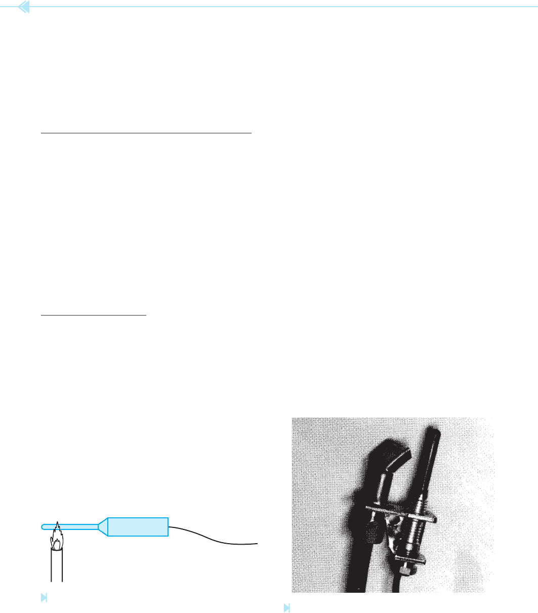
FLAME SENSORS
There are several methods used to sense the pres-
ence of a gas ame. One of the most common is with
the use of a thermocouple. The thermocouple is a
device that produces a voltage when heated. If the
thermocouple is inserted in the gas ame as shown
in Figure 38–1, a voltage will be produced. The volt-
age produced by the thermocouple is used to create
a current ow through the coil of a solenoid. The
current produces a magnetic eld that holds the
valve open. As long as the solenoid receives enough
current, a valve is held open and gas is permitted
to ow to the main burner. If the pilot light should
go out, no voltage will be produced and the pilot
valve will stop the ow of gas. It should be noted
that the thermocouple has the ability to produce
enough current to hold the valve open, but it cannot
produce enough current to reopen the valve if it is
closed. The pilot valve must be opened manually by
pushing the pilot button located on the main valve.
It should also be noted that some controls of this
type are actually thermopiles and not thermocou-
ples. Recall that a thermopile is a series connection
of several thermocouples used to produce a higher
voltage. When replacing a thermocouple, care must
be taken to use the proper type. A thermocouple is
shown in Figure 38–2.
Another type of ame sensor uses pressure. This
control is similar to the pressure type of thermostat.
A refrigerant- lled bulb is located in the pilot ame.
When the refrigerant is heated, a pressure is pro-
duced that holds the pilot safety valve open.
Another type of gas ame sensor is the
“ re
eye” or “ ame eye”. The
re eye is a gas- lled
tube that has a very high resistance in its normal
state and will not conduct electricity. A gas ame
contains ultraviolet (UV) radiation. The ultraviolet
radiation of the gas ame causes the gas in the re
eye to ionize and conduct electricity. Notice that this
type of sensor detects the light of a ame and not the
heat. This type of control is generally used to sense
Figure 38–1
Thermocouple senses pilot fl ame. (Source: Delmar/
Cengage Learning)
PILOT
LIGHT
THERMOCOUPLE
TO GAS CONTROL
VA
LVE
Figure 38–2
Thermocouple and pilot burner.
(Source: Delmar/Cengage Learning)
UNIT 38 Gas Burner Controls 349
the presence of the main burner ame instead of
the pilot ame. Fire eye detectors are generally used
with timers that turn the gas supply off if a ame
is not detected within a certain time after a call
for heat.
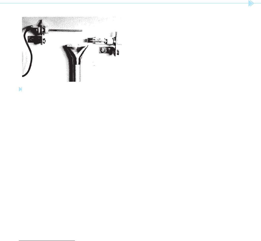
The “ ame rod” is another sensor that is
generally used to detect the presence of ame at the
main burner. The ame rod operates by using the
gas ame as a conductor of electricity. A gas ame
contains many ionized particles that will conduct
electricity in a similar manner to some types of
vacuum tubes. When the ame rod is inserted in
a ame, a current path exists between the rod and
the metal of the burner head itself. As long as there
is a ame, there can be a ow of electricity between
the rod and the burner head. If the ame should
be extinguished, the ow of electricity will stop.
Figure 38–3 shows a photograph of a ame rod, a
small burner head and an electric spark ignitor.
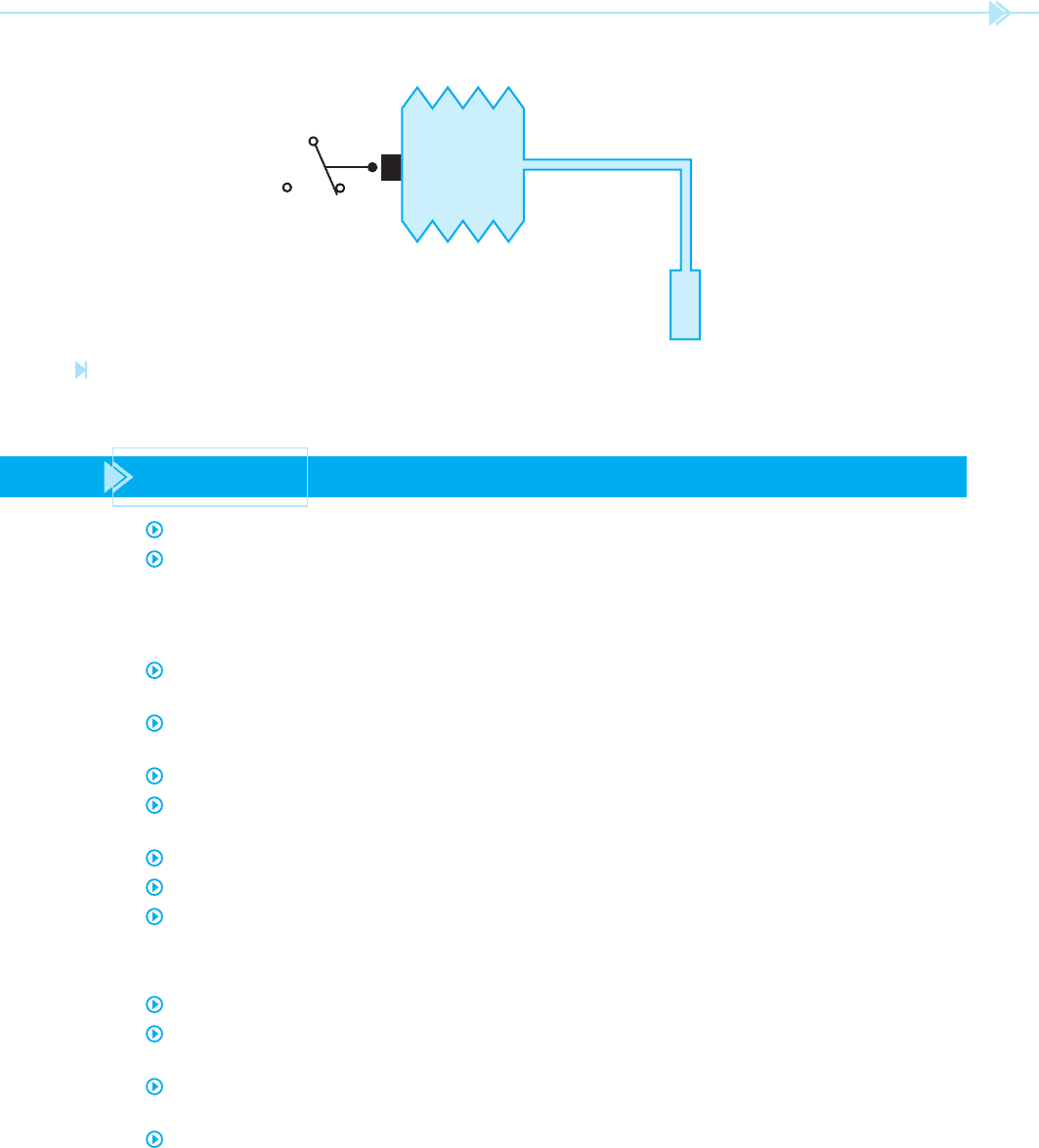
CONTROL VALVES
The gas control valve is the real heart of the gas
heating system. Control valves control the ow of
gas to the main burner and the pilot light, if used.
Many of them contain an internal pressure reg-
ulator, which maintains a constant pressure to the
main burner. A simple gas control valve is shown in
Figure 38–4. This illustration is used to show the
basic principle of operation. This type of valve uses a
thermocouple to detect the presence of a pilot ame.
Figure 38–3
Flame rod, burner head, and high-voltage ignition
electrode. (Source: Delmar/Cengage Learning)
Notice that a spring is used to close the valve if the
thermocouple should stop producing current for the
solenoid coil. Also notice that a solenoid coil is used
to open the main valve when the thermostat calls for
heat. Different valves use different methods of open-
ing the main valve. Some valves use a small electric
heater to heat a bimetal strip that opens the main
valve. Others use a small heater to cause a metal
rod to expand and open the main valve. Regardless
of the method used, all control valves perform the
same basic function.
The schematic in Figure 38–5 shows a basic
control circuit for a gas heating system. Notice that
the fan and high-limit switch are connected in the
120-volt line ahead of the control transformer.
When the thermostat closes, 24 volts AC is applied
to the control valve. This permits the valve to open
and supply gas to the main burner. Notice that this
control valve uses a thermocouple to sense the pres-
ence of a pilot light. If the pilot light should go out,
the pilot valve will close and gas ow to the burner
will stop.
The schematic in Figure 38–6 shows a con-
trol circuit that uses a high-voltage spark ignitor.
Notice that a fan-limit switch is connected ahead of
the 24 volts control transformer. This is the same as
the other type of control. In this circuit, however,
when the thermostat calls for heat, 24 volts AC is
applied to a direct spark ignition control module.
When the control module receives a call for heat,
it turns on the main control valve and provides
about 15,000 volts to the ignition electrode. The
module also starts an electronic timer at the same
time. When the gas is ignited at the burner head,
a current ows from the ame rod to the base of
the burner. This completes a circuit through the
ground wire back to the control module. This ow
of current is used to turn off the timer and electric
ignitor. As long as a ame is present, and the ther-
mostat calls for heat, the main valve is permitted to
remain open. If the ame should go out, however,
current ow between the ame rod and burner
ground will be broken and the timer and electric
ignitor will be started. If a ame is not established in
a predetermined time, the main valve will be turned
off and the ow of gas stopped. Some systems are
equipped with an alarm relay that is turned on by
a solid-state relay when the control module senses
an unsafe condition.