Wai-Fah Chen.The Civil Engineering Handbook
Подождите немного. Документ загружается.

Theory and Analysis of Structures 47-61
Hence,
N
f
is maximum when y = d and
The horizontal component of N
f
is taken by the reinforcing ring provided along the upper edge of the
tank. The vertical components constitute the reactions supporting the tank.
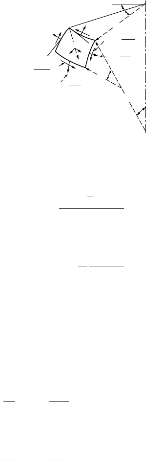
Shells of Revolution Subjected to Unsymmetrical Loading
Consider an element cut from a shell by two adjacent meridients and two parallel circles, as shown in
Fig. 47.48. In general cases, shear forces N
jq
= N
qj
and normal forces N
j
and N
q
will act on the sides of
the element. Projecting the forces on the element in the y direction, we obtain the governing equation:
(47.93)
Similarly the forces in the x direction can be summed up to give
(47.94)
Since the projection of shearing forces on the z axis vanishes, the third equation is the same as Eq. (47.92).
The problem of determining membrane stresses under unsymmetrical loading reduces to solving
Eqs. (47.92) to (47.94) for given values of the components X, Y, and Z of the intensity of the external load.
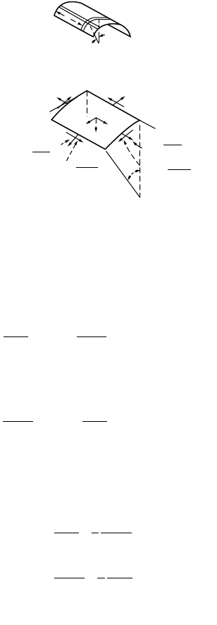
Cylindrical Shells
It is assumed that the generator of the shell is horizontal and parallel to the x axis. An element is cut
from the shell by two adjacent generators and two cross sections perpendicular to the x axis, and its
position is defined by the coordinate x and the angle j. The forces acting on the sides of the element are
shown in Fig. 47.49b.
FIGURE 47.48 Element from shells of revolution — unsymmetrical loading.
θ
N
θ
ϕ
N
ϕθ
N
ϕ
N
θ
y
Y
Z
z
X
x
r
2
r
1
r
0
dϕ
dθ
ϕ
1
N
ϕθ
+
δN
δϕ
ϕθ
dϕ
N
ϕ
+
δN
δϕ
ϕ
dϕ
N
θ
ϕ
+
δN
δθ
θ
ϕ
dθ
N
θ
+
δN
δθ
θ
dθ
f
ga
a
N
yd
2
3
y tan
2cos
=
-
Ê
Ë
Á
ˆ
¯
˜
3
4
--
N
f
ga
a
()
=
max
2
3
16
d
tan
cos
∂
∂
()
+
∂
∂
-+=
jq
j
j
qj
q
Nr
N
rNr
cos Y
rr
0
011 10
∂
∂
()
+
∂
∂
++=
jq
j
jq
q
qj01101
rN
N
rNr
cos X
rr
0
© 2003 by CRC Press LLC
47-62 The Civil Engineering Handbook, Second Edition
The components of the distributed load over the surface of the element are denoted as X, Y, and Z.
Considering the equilibrium of the element and summing up the forces in the x direction, we obtain
The corresponding equations of equilibrium in the y and z directions are given, respectively, as
The three equations of equilibrium can be simplified and represented in the following form:
(47.95)
In each particular case we readily find the value of N
j
. Substituting this value in the second of the
equations, we then obtain N
xj
by integration. Using the value of N
xj
thus obtained, we find N
x
by
integrating the first equation.
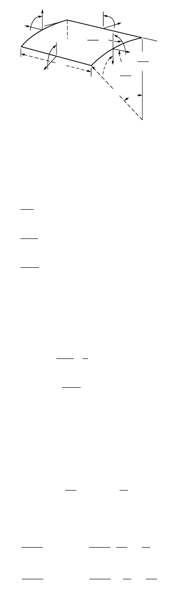
Symmetrically Loaded Circular Cylindrical Shells
To establish the equations required for the solution of a symmetrically loaded circular cylinder shell, we
consider an element, as shown in Figs. 47.49a and 47.50. From symmetry, the membrane shearing forces
N
xj
= N
jx
vanish in this case; forces N
j
are constant along the circumference. From symmetry, only the
forces Q
z
do not vanish. Considering the moments acting on the element in Fig. 47.50, from symmetry
it can be concluded that the twisting moments M
xj
= M
jx
vanish and that the bending moments M
j
are
constant along the circumference. Under such conditions of symmetry, three of the six equations of
equilibrium of the element are identically satisfied. We have to consider only the equations, obtained by
FIGURE 47.49 Membrane forces on a cylindrical shell element.
(a)
ϕ
x
N
x
N
xϕ
N
ϕx
N
ϕ
x
y
Y
Z
X
z
(b)
d
ϕ
δϕ
N
ϕ
+
δN
ϕ
dϕ
δ
ϕ
N
ϕx
+
δN
ϕx
dϕ
δX
δX
N
x
+
δN
x
dx
N
xϕ
+
δN
xϕ
dx
∂
∂
+
∂
∂
+=
N
N
x
x
x
rd dx d dx Xrd dx 0j
j
jj
j
∂
∂
+
∂
∂
+=
+=
x
N
x
rd dx
N
ddxYrd dx 0
N
ddxZrd dx 0
jj
j
j
j
jj
jj
∂
∂
+
∂
∂
=-
∂
∂
+
∂
∂
=-
=-
x
x
x
N
x
1
r
N
X
N
x
1
r
N
Y
j
jj
j
j
j
NZr
© 2003 by CRC Press LLC
Theory and Analysis of Structures 47-63
projecting the forces on the x and z axes and by taking the moment of the forces about the y axis. For
example, consider a case in which external forces consist only of a pressure normal to the surface. The
three equations of equilibrium are
(47.96)
The first one indicates that the forces N
x
are constant, and they are taken equal to zero in the further
discussion. If they are different from zero, the deformation and stress corresponding to such constant
forces can be easily calculated and superposed on stresses and deformations produced by lateral load.
The remaining two equations are written in the simplified form:
(47.97)
These two equations contain three unknown quantities: N
j
, Q
x
, and M
x
. We need, therefore, to consider
the displacements of points in the middle surface of the shell.
The component v of the displacement in the circumferential direction vanishes because of symmetry.
Only the components u and w in the x and z directions, respectively, are to be considered. The expressions
for the strain components then become
(47.98)
By Hooke’s law, we obtain
(47.99)
FIGURE 47.50 Stress resultants in a cylindrical shell element.
Q
x
N
x
dx
M
x
y
z
x
a
M
ϕ
d
ϕ
N
ϕ
N
ϕ
M
ϕ
M
x
+
dM
dx
x
dx
Q
x
+
dQ
dx
x
dx
N
x
+
dN
dx
x
dx
dN
dx
adxd 0j
jjj
jj
j
=
++=
-=
dQ
dx
adxd N dxd Zadxd
dM
dx
adxd Q adxd
x
x
x
0
0
dQ
dx a
NZ
dM
dx
Q
x
x
x
+=-
-=
1
0
j
x
du
dx
w
a
ee
j
==-
x
x
x
N
Eh
1
Eh
1
du
dx
w
a
0
N
Eh
1
Eh
1
w
a
du
dx
0
=
-
+
()
=
-
-
Ê
Ë
Á
ˆ
¯
˜
=
=
-
+
()
=
-
-+
Ê
Ë
Á
ˆ
¯
˜
=
n
e
n
e
n
n
n
e
n
e
n
n
j
j
j
22
22
© 2003 by CRC Press LLC
47-64 The Civil Engineering Handbook, Second Edition
From the first of these equation it follows that
and the second equation gives
(47.100)
Considering the bending moments, we conclude from symmetry that there is no change in curvature in
the circumferential direction. The curvature in the x direction is equal to –d
2
w/dx
2
. Using the same
equations as the ones for plates, we then obtain
(47.101)
where
is the flexural rigidity per unit length of the shell.
Eliminating Q
x
from Eq. (47.97), we obtain
from which, by using Eqs. (47.100) and (47.101), we obtain
(47.102)
All problems of symmetrical deformation of circular cylindrical shells thus reduce to the integration of
Eq. (47.102).
The simplest application of this equation is obtained when the thickness of the shell is constant. Under
such conditions Eq. (47.102) becomes
using the notation
(47.103)
Equation (47.103) can be represented in the simplified form
(47.104)
du
dx
w
a
=n
N
j
=-
Ehw
a
MM
MD
dw
dx
x
x
j
n=
=-
2
2
D
Eh
12 1
3
=
-
()
2
n
2
x
2
dM
dx
1
a
Z+=-N
j
2
2
2
22
d
dx
D
d
w
dx
Eh
a
wZ
Ê
Ë
Á
ˆ
¯
˜
+=
D
d
w
dx
Eh
a
wZ
4
42
+=
4
2
2
22
Eh
4
a
D
31
ah
b
n
==
-
()
4
4
d
w
4w
Z
Ddx
4
+=
b
© 2003 by CRC Press LLC
Theory and Analysis of Structures 47-65
The general solution of this equation is
(47.105)
Detailed treatment of the shell theory can be obtained from Timoshenko and Woinowsky-Krieger (1959)
and Gould (1988).
47.7 Influence Lines
Bridges, industrial buildings with traveling cranes, and frames supporting conveyer belts are often
subjected to moving loads. Each member of these structures must be designed for the most severe
conditions that can possibly be developed in that member. Live loads should be placed at the positions
where they will produce these severe conditions. The critical positions for placing live loads will not be
the same for every member. On some occasions it is possible by inspection to determine where to place
the loads to give the most critical forces, but on many other occasions it is necessary to resort to certain
criteria to find the locations. The most useful of these methods is the influence lines.
An influence line for a particular response such as reaction, shear force, bending moment, and axial
force is defined as a diagram, the ordinate to which at any point equals the value of that response
attributable to a unit load acting at that point on the structure. Influence lines provide a systematic
procedure for determining how the force in a given part of a structure varies as the applied load moves
about on the structure. Influence lines of responses of statically determinate structures consist only of
straight lines, whereas for statically indeterminate structures they consist of curves. They are primarily
used to determine where to place live loads to cause maximum force and to compute the magnitude of
those forces. The knowledge of influence lines helps to study the structural response under different
moving load conditions.
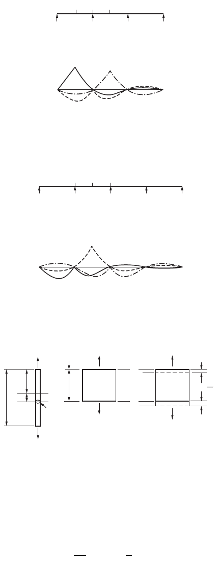
Influence Lines for Shear in Simple Beams
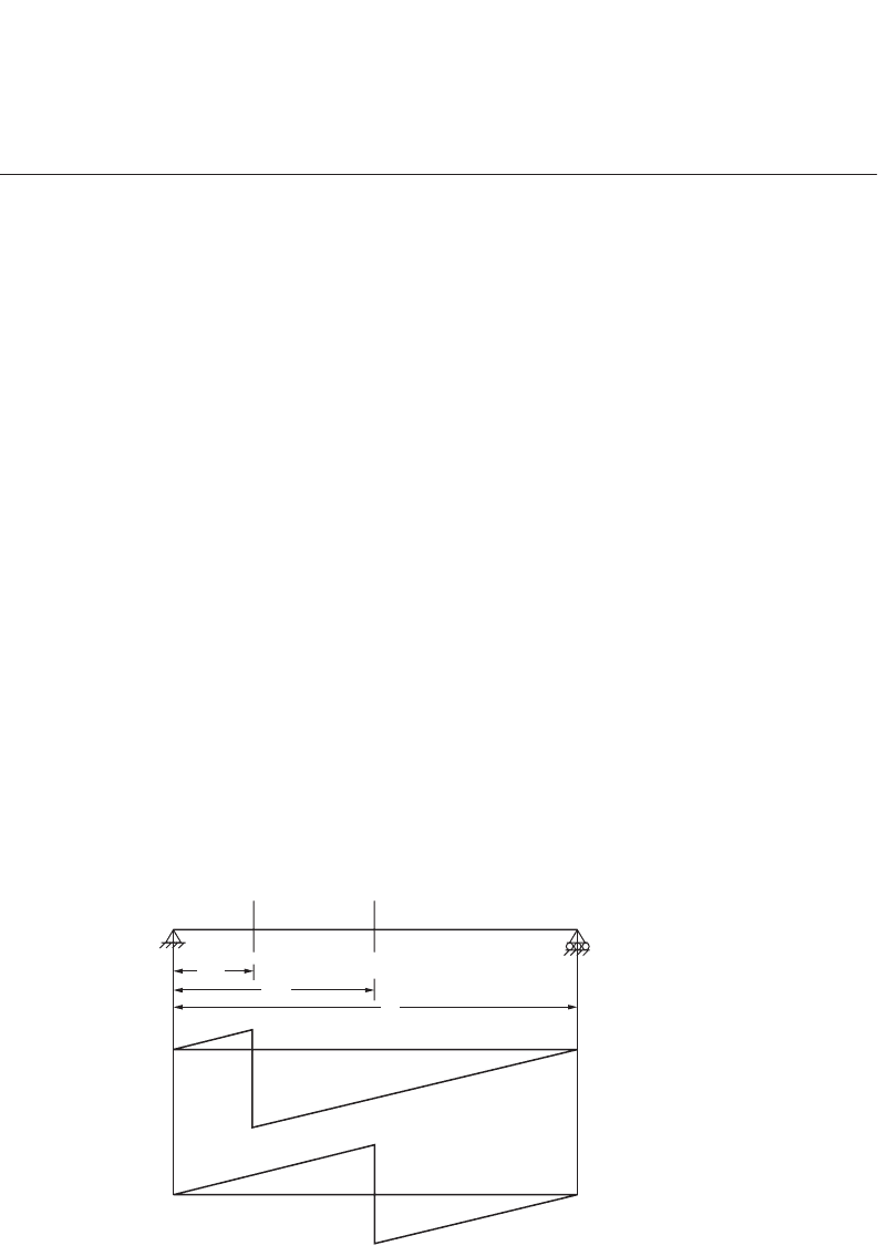
Figure 47.51 shows influence lines for shear at two sections of a simply supported beam. It is assumed
that positive shear occurs when the sum of the transverse forces to the left of a section is in the upward
direction or when the sum of the forces to the right of the section is downward. A unit force is placed
at various locations, and the shear forces at sections 1-1 and 2-2 are obtained for each position of the
unit load. These values give the ordinate of influence line with which the influence line diagrams for
shear force at sections 1-1 and 2-2 can be constructed. Note that the slope of the influence line for shear
FIGURE 47.51 Influence line for shear force.
weC xC x e C xC x fx
xx
=+
()
++
()
+
()
-bb
bb bb
12 34
cos sin cos sin
1
0.2
0.5
0.8
0.5
1
2
2
/
2
/
5
Influence line for
shear at 1−1
Influence line for
shear at 2−2
−
−
+
+
© 2003 by CRC Press LLC
47-66 The Civil Engineering Handbook, Second Edition
on the left of the section is equal to the slope of the influence line on the right of the section. This
information is useful in drawing shear force influence lines in other cases.
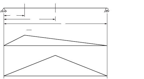
Influence Lines for Bending Moment in Simple Beams
Influence lines for bending moment at the same sections, 1-1 and 2-2, of the simple beam considered
in Fig. 47.51 are plotted as shown in Fig. 47.52. For a section, when the sum of the moments of all the
forces to the left is clockwise or when the sum to the right is counterclockwise, the moment is taken as
positive. The values of bending moment at sections 1-1 and 2-2 are obtained for various positions of
unit load and plotted as shown in the figure.
It should be understood that a shear or bending moment diagram shows the variation of shear or
moment across an entire structure for loads fixed in one position. On the other hand, an influence line
for shear or moment shows the variation of that response at one particular section in the structure caused
by the movement of a unit load from one end of the structure to the other.
Influence lines can be used to obtain the value of a particular response for which they are drawn when
the beam is subjected to any particular type of loading. If, for example, a uniform load of intensity q
o
per unit length is acting over the entire length of the simple beam shown in Fig. 47.51, the shear force
at section 1-1 is given by the product of the load intensity, q
o
, and the net area under the influence line
diagram. The net area is equal to 0.3, and the shear force at section 1-1 is therefore equal to 0.3 q
o
. In
the same way, the bending moment at the section can be found as the area of the corresponding influence
line diagram times the intensity of loading, q
o
. The bending moment at the section is equal to 0.08q
o
l
2
.
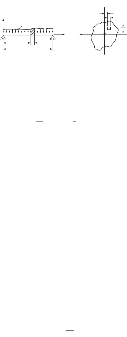
Influence Lines for Trusses
Influence lines for support reactions and member forces may be constructed in the same manner as those
for various beam functions. They are useful to determine the maximum load that can be applied to the
truss. The unit load moves across the truss, and the ordinates for the responses under consideration may
be computed for the load at each panel point. Member force, in most cases, does not need to be calculated
for every panel point, because certain portions of influence lines can readily be seen to consist of straight
lines for several panels. One method used for calculating the forces in a chord member of a truss is the
method of sections, discussed earlier.
The truss shown in Fig. 47.53 is considered for illustrating the construction of influence lines for
trusses.
The member forces in U
1
U
2
, L
1
L
2
, and U
1
L
2
are determined by passing section 1-1 and considering
the equilibrium of the free-body diagram of one of the truss segments. Unit load is placed at L
1
first,
and the force in U
1
U
2
is obtained by taking the moment about L
2
of all the forces acting on the right-
hand segment of the truss and dividing the resulting moment by the lever arm (the perpendicular distance
FIGURE 47.52 Influence line for bending moment.
1
1
2
2
/
5
/
2
_
4
Influence line for
bending moment
at 1−1
Influence line for
bending moment
at 2−2
25
4
© 2003 by CRC Press LLC
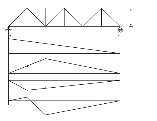
Theory and Analysis of Structures 47-67
of the force in U
1
U
2
from L
2
). The value thus obtained gives the ordinate of the influence diagram at L
1
in the truss. The ordinate at L
2
, obtained similarly, represents the force in U
1
U
2
for a unit load placed at
L
2
. The influence line can be completed with two other points, one at each of the supports. The force in
the member L
1
L
2
due to a unit load placed at L
1
and L
2
can be obtained in the same manner, and the
corresponding influence line diagram can be completed. By considering the horizontal component of
force in the diagonal of the panel, the influence line for force in U
1
L
2
can be constructed. Figure 47.53
shows the respective influence diagram for member forces in U
1
U
2
, L
1
L
2
, and U
1
L
2
. Influence line ordinates
for the force in a chord member of a “curved chord” truss may be determined by passing a vertical section
through the panel and taking moments at the intersection of the diagonal and the other chord.
Qualitative Influence Lines
One of the most effective methods of obtaining influence lines is using Müller-Breslau’s principle, which
states that the ordinates of the influence line for any response in a structure are equal to those of the
deflection curve obtained by releasing the restraint corresponding to this response and introducing a
corresponding unit displacement in the remaining structure. In this way, the shape of the influence lines
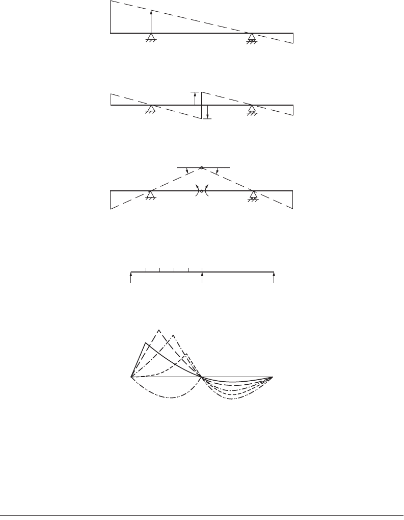
for both statically determinate and indeterminate structures can be easily obtained, especially for beams.
To draw the influence lines of a
1. support reaction, remove the support and introduce a unit displacement in the direction of the
corresponding reaction to the remaining structure, as shown in Fig. 47.54, for a symmetrical
overhang beam.
2. shear, make a cut at the section and introduce a unit relative translation (in the direction of positive
shear) without relative rotation of the two ends at the section, as shown in Fig. 47.55.
3. bending moment, introduce a hinge at the section (releasing the bending moment) and apply
bending (in the direction corresponding to the positive moment) to produce a unit relative rotation
of the two beam ends at the hinged section, as shown in Fig. 47.56.
Influence Lines for Continuous Beams
Using Müller-Breslau’s principle, the shape of the influence line of any response of a continuous beam
can be sketched easily. One of the methods for beam deflection can then be used for determining the
FIGURE 47.53 Influence line for truss.
U
1
U
2
U
3
U
4
U
5
L
1
L
0
L
2
L
3
L
4
L
5
L
6
1
1
6 m
6 @ 6 m = 36 m
1.0
0.67
1.33
0.68
0.83
0.24
0.94
+
+
−
−
Influence line for
reaction at L
0
Influence line for
force in U
1
U
2
Influence line for
force in L
1
L
2
Influence line for
force in U
1
L
2
© 2003 by CRC Press LLC
47-68 The Civil Engineering Handbook, Second Edition
ordinates of the influence line at critical points. Figures 47.57 to 47.59 show the influence lines of the
bending moment at various points of two-, three-, and four-span continuous beams.
47.8 Energy Methods
Energy methods are a powerful tool in obtaining numerical solutions of statically indeterminate problems.
The basic quantity required is the strain energy, or work stored due to deformations, of the structure.
Strain Energy Due to Uniaxial Stress
In an axially loaded bar with a constant cross section the applied load causes normal stress s
y
, as shown
in Fig. 47.60. The tensile stress s
y
increases from zero to a value s
y
as the load is gradually applied. The
FIGURE 47.54 Influence line for support reaction.
FIGURE 47.55 Influence line for midspan shear force.
FIGURE 47.56 Influence line for midspan bending moment.
FIGURE 47.57 Influence line for bending moment — two-span beam.
1.0
0.5
0.5
0.50.5
01
1
2
2
3
3
4
4
5
5
0.150
0.206
0.182
0.102
0.096
0.096
© 2003 by CRC Press LLC
Theory and Analysis of Structures 47-69
original, unstrained position of any section such as C-C will be displaced by an amount dv. A section
D-D located a differential length below C-C will have been displaced by an amount v + (∂v/∂y)dy. As s
y
varies with the applied load, from zero to s
y
, the work done by the forces external to the element can be
shown to be
(47.106)
in which A = the area of cross section of the bar
e
y
= the strain in the direction of s
y
.
FIGURE 47.58 Influence line for bending moment — three-span beam.
FIGURE 47.59 Influence line for bending moment — four-span beam.
FIGURE 47.60 Axial loaded bar.
01
1
2
2
3
3
0.175
0.200
0.102
0123
1
2
3
0.103
0.086
0.173
P
P
L
C
y
y
V
D
C
C
D
D
C
C′
C′
D′
D′
D
A
dy
dy
σ
y
= 0
σ
y
= 0
σ
y
≠ 0
σ
y
≠ 0
v +
δ
δ
v
y
dy
(a) (b) (c)
dV
1
2E
Ady
1
2
Ady
y
2
yy
==
ss
e
© 2003 by CRC Press LLC
47-70 The Civil Engineering Handbook, Second Edition
Strain Energy in Bending
It can be shown that the strain energy of a differential volume dxdydz stressed in tension or compression
in the x direction only by a normal stress s
x
will be
(47.107)
When s
x
is the bending stress given by s
x
= My/I (see Fig. 47.61), then
where I is the moment of inertia of the cross-sectional area about the neutral axis.
The total strain energy of bending of a beam is obtained as
where
Therefore
(47.108)
Strain Energy in Shear
Figure 47.62 shows an element of volume dxdydz subjected to shear stress t
xy
and t
yx
. For static equilib-
rium, it can readily be shown that
t
xy
= t
yx
The shear strain, g, is defined as AB/AC. For small deformations, it follows that
Hence, the angle of deformation, g
xy
, is a measure of the shear strain. The strain energy for this differential
volume is obtained as
FIGURE 47.61 Beam under arbitrary bending load.
y
y
y
L
(a)
(b)
p(x)
x
x
z
z
dx
C.G.
dz
dy
dV
1
2E
dxdydz
1
2
dxdydz
x
2
xx
==
ss
e
dV
E
My
I
dxdydz=
1
2
22
2
,
V
E
M
I
ydzdydx
volume
=
ÚÚÚ
1
2
2
2
2
Iydzdy
area
=
ÚÚ
2
V
M
2EI
dx
2
=
Ú
length
xy
AB
AC
g
=
© 2003 by CRC Press LLC