Wai-Fah Chen.The Civil Engineering Handbook
Подождите немного. Документ загружается.

48-14 The Civil Engineering Handbook, Second Edition
Check for the limit state of block shear:
Figure 48.4c shows a possible block shear failure mode. To avoid block shear failure, the required strength
of P
u
= 104 kips should not exceed the design strength, f
t
P
n
, calculated using Eq. (48.12a) or (48.12b),
whichever is applicable.
For the C8x11.5 section:
Substituting the above into Eq. (48.12b), since [F
u
A
nt
= 23.8 kips] is smaller than [0.6F
u
A
nv
= 94.7 kips],
we obtain f
t
P
n
= 88.8 kips, which is less than P
u
= 104 kips. The C8x11.5 section is therefore not adequate.
Significant increase in block shear strength is not expected from the C9x13.4 section because its web
thickness t
w
is just slightly over that of the C8x11.5 section. As a result, we shall check the adequacy of
the C8x13.75 section instead.
For the C8x13.75 section:
Substituting the above into Eq. (48.12b), since [F
u
A
nt
= 33.1 kips] is smaller than [0.6F
u
A
nv
= 130.5 kips],
we obtain f
t
P
n
= 122 kips, which exceeds the required strength P
u
of 104 kips. Therefore, block shear
will not be a problem for the C8x13.75 section.
Check for the limiting slenderness ratio:
Using the parallel axis theorem, the least radius of gyration of the double-channel cross section is
calculated to be 0.96 in. Therefore, L/r = (15 ft)(12 in./ft)/0.96 in. = 187.5, which is less than the
recommended maximum value of 300.
Check for the adequacy of the connection:
An example of the calculations is shown in Section 48.11.
Longitudinal spacing of connectors:
According to Section J3.5 of the LRFD specification, the maximum spacing of connectors in built-up
tension members shall not exceed:
• 24 times the thickness of the thinner plate or 12 in. (305 mm) for painted members or unpainted
members not subject to corrosion
• 14 times the thickness of the thinner plate or 7 in. (180 mm) for unpainted members of weathering
steel subject to atmospheric corrosion
Assuming the first condition applies, a spacing of 6 inches is to be used.
Use 2C8x13.75 connected intermittently at 6-in. intervals.
A
AA
A
AA
gv
nv gv
gt
nt gt
=
()( )
=
=-+
()
()
=
=
()( )
=
=-+
()
()
=
29 396
18
18
0.220 .
in
51 0.220 2.72
in
3 0.220 0.66
in
11 0.220 0.41
in
2
2
2
2
A
AA
A
AA
gv
nv gv
gt
nt gt
=
()( )
=
=-+
()
()
=
=
()( )
=
=-+
()
()
=
29 0303 5 45
1180303
30303
1180303
..
in
5.3.75
in
. 0.91
in
1.0.57
in
2
2
2
2
© 2003 by CRC Press LLC
Design of Steel Structures 48-15
Pin-Connected Members
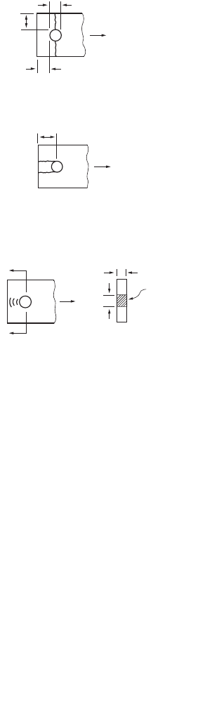
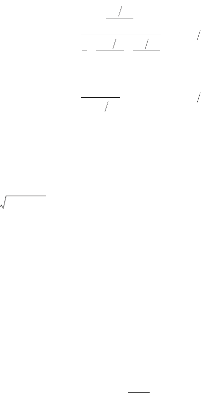
Pin-connected members shall be designed to preclude the following failure modes: (1) tension yielding
in the gross section, (2) tension fracture on the effective net area, (3) longitudinal shear on the effective
area, and (4) bearing on the projected pin area (Fig. 48.5).
Allowable Stress Design
The allowable stresses for tension yield, tension fracture, and shear rupture are 0.60F
y
, 0.45F
y
, and 0.30F
u
,
respectively. The allowable stresses for bearing are given in Section 48.11.
Load and Resistance Factor Design
The design tensile strength f
t
P
n
for pin-connected members is given as follows:
Tension on gross area: see Eq. (48.10).
Tension on effective net area:
(48.13)
Shear on effective area:
(48.14)
Bearing on projected pin area: see Section 48.11.
The terms in Fig. 48.5 and the above equations are defined as follows:
a = shortest distance from edge of the pin hole to the edge of the member measured in the direction
of the force
A
pb
= projected bearing area = dt
FIGURE 48.5 Failure modes of pin-connected members.
d
b
a
a+d/2
At
d
Section A-A
Projected Bearing
Area, A
pb
= dt
Bearing
A
Longitudinal Shear
Tension Fracture
tn
eff u
P t
b
F
f
=
[]
075 2.
sf n
sf u
P
A
F
f
=
[]
075 06..
© 2003 by CRC Press LLC
48-16 The Civil Engineering Handbook, Second Edition
A
sf
= 2t(a + d/2)
b
eff
= 2t + 0.63 in. (or 2t +16 mm), but not more than the actual distance from the edge of the hole
to the edge of the part measured in the direction normal to the applied force
d = pin diameter
t = plate thickness
Threaded Rods
Allowable Stress Design
Threaded rods under tension are treated as bolts subject to tension in allowable stress design. These
allowable stresses are given in the Section 48.11.
Load and Resistance Factor Design
Threaded rods designed as tension members shall have a gross area A
b
given by
(48.15)
where A
b
= the gross area of the rod computed using a diameter measured to the outer extremity of
the thread
P
u
= the factored tensile load
f = the resistance factor given as 0.75
P
u
= the specified minimum tensile strength.
48.4 Compression Members
Members under compression can fail by yielding, inelastic buckling, or elastic buckling, depending on the
slenderness ratio of the members. Members with low slenderness ratios tend to fail by yielding, while
members with high slenderness ratios tend to fail by elastic buckling. Most compression members used in
construction have intermediate slenderness ratios, so the predominant mode of failure is inelastic buckling.
Overall member buckling can occur in one of three different modes: flexural, torsional, and flexural–tor-
sional. Flexural buckling occurs in members with doubly symmetric or doubly antisymmetric cross sections
(e.g., I or Z sections) and in members with singly symmetric sections (e.g., channel, tee, equal-legged angle,
and double angle sections) when such sections are buckled about an axis that is perpendicular to the axis
of symmetry. Torsional buckling occurs in members with doubly symmetric sections such as cruciform or
built-up shapes with very thin walls. Flexural–torsional buckling occurs in members with singly symmetric
cross sections (e.g., channel, tee, equal-legged angle, and double-angle sections) when such sections are
buckled about the axis of symmetry and in members with unsymmetric cross sections (e.g., unequal-legged
L). Normally, torsional buckling of symmetric shapes is not particularly important in the design of hot-
rolled compression members. Either it does not govern or its buckling strength does not differ significantly
from the corresponding weak-axis flexural buckling strengths. However, torsional buckling may become
important for open sections with relatively thin component plates. It should be noted that for a given cross-
sectional area, a closed section is much stiffer torsionally than an open section. Therefore, if torsional
deformation is of concern, a closed section should be used. Regardless of the mode of buckling, the governing
effective slenderness ratio (Kl/r) of the compression member preferably should not exceed 200.
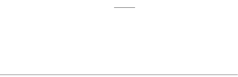
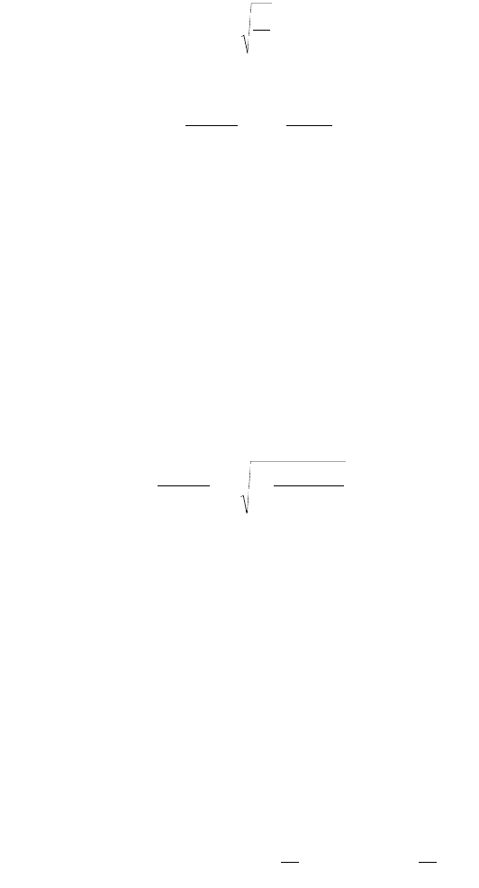
In addition to the slenderness ratio and cross-sectional shape, the behavior of compression members
is affected by the relative thickness of the component elements that constitute the cross section. The
relative thickness of a component element is quantified by the width–thickness ratio (b/t) of the element.
The width–thickness ratios of some selected steel shapes are shown in Fig. 48.6. If the width–thickness
ratio falls within a limiting value (denoted by the LRFD Specification [AISC, 1999] as l
r
) as shown in
Table 48.4, the section will not experience local buckling prior to overall buckling of the member.
A
P
F
b
u
u
≥
f 075.
© 2003 by CRC Press LLC
Design of Steel Structures 48-17
FIGURE 48.6 Definition of width–thickness ratio of selected cross sections.
TA BLE 48.4 Limiting Width–Thickness Ratios for Compression Elements under Pure
Compression
Component Element
Width–Thickness
Ratio Limiting Value, l
r
Flanges of I-shaped sections; plates projecting from
compression elements; outstanding legs of pairs of angles
in continuous contact; flanges of channels
b/t
0.56
Flanges of square and rectangular box and hollow structural
sections of uniform thickness; flange cover plates and
diaphragm plates between lines of fasteners or welds
b/t
1.40
Unsupported width of cover plates perforated with a
succession of access holes
b/t
1.86
Legs of single-angle struts; legs of double-angle struts with
separators; unstiffened elements (i.e., elements supported
along one edge)
b/t
0.45
Flanges projecting from built-up members b/t
0.64
Stems of tees d/t
0.75
All other uniformly compressed stiffened elements (i.e.,
elements supported along two edges)
b/t
h/t
w
a
1.49
Circular hollow sections D/t
b
0.11E/F
y
a
h = web depth, t
w
= web thickness.
b
D = outside diameter, t = wall thickness.
c
E = modulus of elasticity, F
y
= specified minimum yield stress, k
c
= 4/÷(h/t
w
); 0.35 £ k
c
£ 0.763 for I-shaped
sections, and k
c
= 0.763 for other sections.
b
f
b
f
b
f
t
w
b
f
t
w
b
f
t
f
t
f
t
b
f
b
b
h
t
d
d
Both Legs: b/t
t
f
t
f
t
f
t
w
t
w
t
w
h
h
h
Flange: b
f
/2t
f
Web: h/t
w
Flange: b
f
/t
f
Web: d/t
w
Flange: b
f
/t
f
Web: h/t
w
Flange: (b
f
-3t)/t
Web: (d - 3t)/t
Flange: b
f
/2t
f
Web: h/t
w
Flange: b
f
/t
f
Web: h/t
w
EF
y
§
EF
y
§
EF
y
§
EF
y
§
EF
y
k
c
§()§
EF
y
§
EF
y
§
© 2003 by CRC Press LLC
48-18 The Civil Engineering Handbook, Second Edition
However, if the width–thickness ratio exceeds this limiting width–thickness value, consideration of local
buckling in the design of the compression member is required.
To facilitate the design of compression members, column tables for W, tee, double-angle, square and
rectangular tubular, and circular pipe sections are available in the AISC manuals for both allowable stress
design [AISC, 1989] and load and resistance factor design [AISC, 2001].
Compression Member Design
Allowable Stress Design
The computed compressive stress f
a
in a compression member shall not exceed its allowable value given by
(48.16)
where Kl/r = the slenderness ratio
K = the effective length factor of the compression member in the plane of buckling
l = the unbraced member length in the plane of buckling
r = the radius of gyration of the cross section about the axis of buckling
E = the modulus of elasticity
C
c
= is the slenderness ratio that demarcates inelastic from elastic member buck-
ling. Kl/r should be evaluated for both buckling axes, and the larger value should be used
in Eq. (48.16) to compute F
a
.
The first of Eq. (48.16) is the allowable stress for inelastic buckling; the second is the allowable stress
for elastic buckling. In ASD, no distinction is made between flexural, torsional, and flexural–torsional
buckling.
Load and Resistance Design
Compression members are to be designed so that the design compressive strength f
c
P
n
will exceed the
required compressive strength P
u
. f
c
P
n
is to be calculated as follows for the different types of overall
buckling modes:
Flexural buckling (with a width–thickness ratio of £ l
r
):
(48.17)
where l
c
=(KL/rp)÷(F
y
/E) is the slenderness parameter
A
g
= the gross cross-sectional area
F
y
= the specified minimum yield stress
E = the modulus of elasticity
K = the effective length factor
a
c
y
cc
c
c
F
Kl r
C
F
Kl r
C
Kl r
C
, KlrC
E
Kl r
, KlrC
=
-
()
È
Î
Í
Í
˘
˚
˙
˙
+
()
-
()
£
()
>
Ï
Ì
Ô
Ô
Ô
Ô
Ô
Ô
Ó
Ô
Ô
Ô
Ô
Ô
Ô
1
2
5
3
3
88
12
23
2
2
3
3
2
2
if
if
p
2p
2
EF
y
§()
cn
gyc
g
c
yc
P
AF ,
AF ,
c
f
l
l
l
l
=
()
È
Î
Í
˘
˚
˙
£
Ê
Ë
Á
ˆ
¯
˜
È
Î
Í
˘
˚
˙
>
Ï
Ì
Ô
Ô
Ó
Ô
Ô
085 0658 15
085
0 877
15
2
2
.. .
.
.
.
if
if
© 2003 by CRC Press LLC
Design of Steel Structures 48-19
l = the unbraced member length in the plane of buckling
r = the radius of gyration of the cross section about the axis of buckling
The first of Eq. (48.17) is the design strength for inelastic buckling; the second is the design strength
for elastic buckling. The slenderness parameter l
c
= 1.5 demarcates inelastic from elastic behavior.
Torsional buckling (with a width–thickness ratio of £ l
r
):
f
c
P
n
is to be calculated from Eq. (48.17), but with l
c
replaced by l
e
given by
(48.18)
where
(48.19)
in which C
w
= the warping constant
G = the shear modulus, which equals 11,200 ksi (77,200 MPa)
I
x
and I
y
= the moments of inertia about the major and minor principal axes, respectively
J = the torsional constant
K
z
= the effective length factor for torsional buckling
The warping constant C
w
and the torsional constant J are tabulated for various steel shapes in the
AISC-LRFD manual [AISC, 2001]. Equations for calculating approximate values for these constants for
some commonly used steel shapes are shown in Table 48.5.
Flexural–torsional buckling (with a width–thickness ratio of £ l
r
):
Same as for torsional buckling, except F
e
is now given by:
For singly symmetric sections:
(48.20)
where F
es
= F
ex
if the x axis is the axis of symmetry of the cross section, or = F
ey
if the y axis is the axis
of symmetry of the cross section
F
ex
= p
2
E/(Kl/r)
x
2
; F
ey
= p
2
E/(Kl/r)
x
2
H =1 – (x
o
2
+ y
o
2
)/r
o
2
, in which K
x
and K
y
are the effective length factors for buckling about
the x and y axes, respectively
l = the unbraced member length in the plane of buckling
r
x
and r
y
= the radii of gyration about the x and y axes, respectively
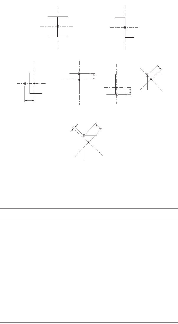
x
o
and y
o
= the shear center coordinates with respect to the centroid (Fig. 48.7), r
o
2
= x
o
2
+ y
o
2
+ r
x
2
+ r
y
2
.
Numerical values for r
o
and H are given for hot-rolled W, channel, tee, single-angle, and double-angle
sections in the AISC-LRFD manual [AISC, 2001].
For unsymmetric sections:
F
e
is to be solved from the cubic equation
(48.21)
The terms in the above equations are defined the same as in Eq. (48.20).
l
e
y
e
F
F
=
F
E C
K L
GJ
II
e
w
z
xy
=
()
+
È
Î
Í
Í
˘
˚
˙
˙
+
p
2
2
1
F
FF
H
F F H
FF
e
es ez es ez
es ez
=
+
--
+
()
È
Î
Í
Í
˘
˚
˙
˙
2
11
4
2
FFFFFF F FF
x
r
F F F
y
r
eexeeyeez eeey
o
o
ee ex
o
o
-
()
-
()
-
()
--
()
Ê
Ë
Á
ˆ
¯
˜
--
()
Ê
Ë
Á
ˆ
¯
˜
=
2
2
2
2
0
© 2003 by CRC Press LLC
48-20 The Civil Engineering Handbook, Second Edition
Local buckling (with a width–thickness ratio of ≥ l
r
):
Local buckling in the component element of the cross section is accounted for in design by introducing
a reduction factor Q in Eq. (48.17) as follows:
(48.22)
where l = l
c
for flexural buckling and l = l
e
for flexural–torsional buckling.
The Q factor is given by
(48.23)
where Q
s
= the reduction factor for unstiffened compression elements of the cross section (see
Table 48.6)
Q
a
= the reduction factor for stiffened compression elements of the cross section (see Table 48.7).
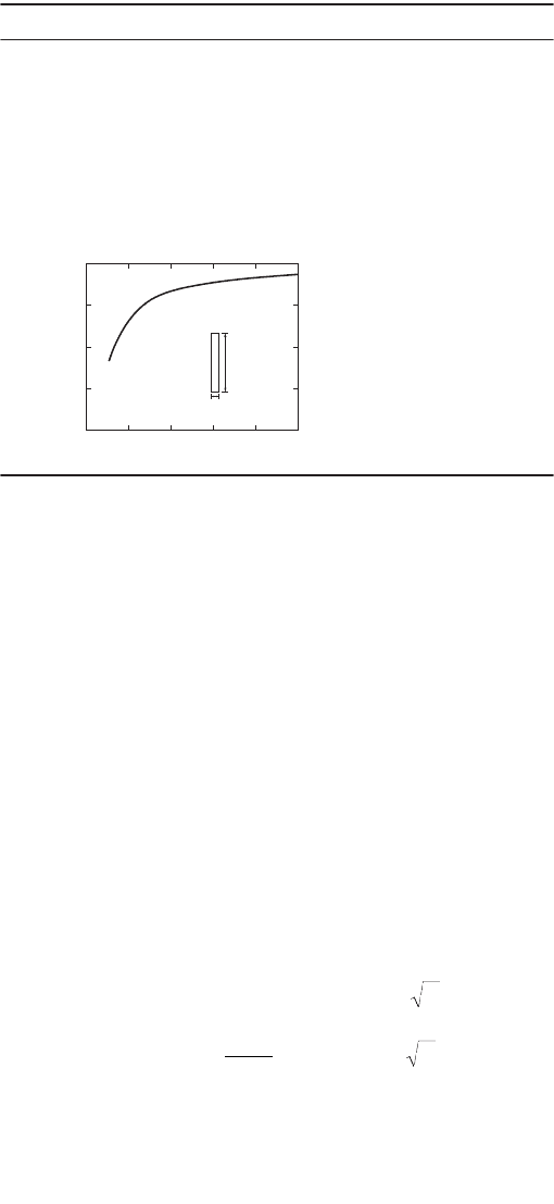
TABLE 48.5 Approximate Equations for C
w
and J
Structural Shape Warping Constant, C
w
To rsional Constant, J
I h¢
2
I
c
I
t
/(I
c
+I
t
) ÂC
i
(b
i
t
i
3
/3)
a
b
i
/t
i
C
i
1.00 0.423
1.20 0.500
1.50 0.588
1.75 0.642
2.00 0.687
2.50 0.747
3.00 0.789
4.00 0.843
5.00 0.873
6.00 0.894
8.00 0.921
10.00 0.936
• 1.000
C(b¢ – 3E
o
)h¢
2
b¢
2
t
f
/6 + E
o
2
I
x
where
E
o
= b¢
2
t
f
/(2b¢t
f
+ h¢t
w
/3)
T(b
f
3
t
f
3
/4 + h≤
3
t
w
3
)/36
(ª0 for small t)
L(l
1
3
t
1
3
+ l
2
3
t
2
3
)/36
(ª0 for small t)
Note:
b¢ = distance measured from toe of flange to centerline of web
h¢ = distance between centerlines of flanges
h≤ = distance from centerline of flange to tip of stem
l
1
, l
2
= length of the legs of the angle
t
1
, t
2
= thickness of the legs of the angle
b
f
= flange width
t
f
= average thickness of flange
t
w
= thickness of web
I
c
= moment of inertia of compression flange taken about the axis of
the web
I
t
= moment of inertia of tension flange taken about the axis of the web
I
x
= moment of inertia of the cross section taken about the major prin-
cipal axis
a
b
i
= width of component element i, t
i
= thickness of component element i,
C
i
= correction factor for component element i.
b
t
1.00
0.75
0.50
0.25
0246
Aspect Ratio, b/t
Correction Factor, C
810
cn
g
Q
y
g
2
y
P
AQ F Q
AF Q
f
l
l
l
l
=
()
È
Î
Í
˘
˚
˙
£
Ê
Ë
Á
ˆ
¯
˜
È
Î
Í
˘
˚
˙
>
Ï
Ì
Ô
Ô
Ó
Ô
Ô
085 0658 15
085
0 877
15
2
.., .
.
.
,.
if
if
QQQ
sa
=
© 2003 by CRC Press LLC
Design of Steel Structures 48-21
FIGURE 48.7 Location of shear center for selected cross sections.
TABLE 48.6
Formulas for Q
s
Structural Element Range of b/t Q
s
Single angles 0.45÷(E/F
y
) < b/t <0.91÷(E/F
y
)
b/t ≥ 0.91÷(E/F
y
)
1.340 – 0.76(b/t)÷(F
y
/E)
0.53E/[F
y
(b/t)
2
]
Flanges, angles,
and plates
projecting from
columns or other
compression
members
0.56÷(E/F
y
) < b/t < 1.03÷(E/F
y
)
b/t ≥ 1.03÷(E/F
y
)
1.415 – 0.74(b/t)÷(F
y
/E)
0.69E/[F
y
(b/t)
2
]
Flanges, angles,
and plates
projecting from
built-up columns
or other
compression
members
0.64÷(E/(F
y
/k
c
)] < b/t < 1.17÷[(E/(F
y
/k
c
)]
b/t ≥ 1.17÷[E/(F
y
/k
c
)]
1.415 – 0.65(b/t)÷(F
y
/k
c
E)
0.90E k
c
/[F
y
(b/t)
2
]
Stems of tees 0.75÷ E/F
y
) < d/t < 1.03÷(E/F
y
)
d/t ≥ 1.03÷(E/F
y
)
1.908 – 1.22(d/t)÷(F
y
/E)
0.69E/[F
y
(b/t)
2
]
Note: k
c
is defined in the footnote of Table 48.4, E = modulus of elasticity, F
y
= specified
minimum yield stress, b = width of the component element, d = depth of tee sections, t =
thickness of the component element.
y
y
y
x
xx
x
x
z
x
xx
y
y
y
y
w
w
w
z
y
y
x
0
=y
0
=0 x
0
=y
0
=0
y
0
=0
y
0
y
0
y
0
x
0
=0
x
0
x
0
x
0
=0
y
0
=0
x
0
© 2003 by CRC Press LLC
48-22 The Civil Engineering Handbook, Second Edition
Built-up Compression Members
Built-up members are members made by bolting or welding together two or more standard structural
shapes. For a built-up member to be fully effective (i.e., if all component structural shapes are to act as
one unit, rather than as individual units), the following conditions must be satisfied:
1. Slippage of component elements near the ends of the built-up member must be prevented.
2. Adequate fasteners must be provided along the length of the member.
3. The fasteners must be able to provide sufficient gripping force on all component elements.
Condition 1 is satisfied if all component elements in contact near the ends of the built-up member
are connected by a weld having a length not less than the maximum width of the member or by bolts
spaced longitudinally not more than four diameters apart for a distance equal to one and a half times
the maximum width of the member. Condition 2 is satisfied if continuous welds are used throughout
the length of the built-up compression member. Condition 3 is satisfied if either welds or fully tightened
bolts are used as the fasteners. Although condition 1 is mandatory, conditions 2 and 3 can be violated
in design. If condition 2 or condition 3 is violated, the built-up member is not fully effective and slight
slippage among component elements may occur. To account for the decrease in capacity due to slippage,
a modified slenderness ratio is used to compute the design compressive strength when buckling of the
built-up member is about an axis coinciding or parallel to at least one plane of contact for the component
shapes. The modified slenderness ratio (Kl/r)
m
is given as follows:
If condition 2 is violated:
(48.24)
TA BLE 48.7 Formula for Q
a
The effective area is equal to the summation of the effective areas of the stiffened elements of the cross section.
The effective area of a stiffened element is equal to the product of its thickness, t, and its effective width,
b
e
, given by
For flanges of square and rectangular sections of uniform thickness, when b/t ≥ 1.40÷(E/f )
a
:
For other noncircular uniformly compressed elements, when b/t ≥ 1.49÷(E/f )
a
:
For axially loaded circular sections with 0.11E/F
y
< D/t < 0.45E/F
y
:
Note: b = actual width of the stiffened element, t = wall thickness, E = modulus of elasticity, f = computed
elastic compressive stress in the stiffened elements, D = outside diameter of circular sections.
a
b
e
= b otherwise.
Q
effective area
actual area
s
=
bt
E
f
bt
E
f
b
e
=-
()
È
Î
Í
Í
˘
˚
˙
˙
£191 1
038
.
.
bt
E
f
bt
E
f
b
e
=-
()
È
Î
Í
Í
˘
˚
˙
˙
£191 1
034
.
.
Q
E
FDt
a
y
=
()
+
0 038 2
3
.
mo
ib
KL
r
KL
r
+
a
r
Ê
Ë
Á
ˆ
¯
˜
=
Ê
Ë
Á
ˆ
¯
˜
+
()
Ê
Ë
Á
ˆ
¯
˜
2
2
2
2
082
1
. a
a
© 2003 by CRC Press LLC
Design of Steel Structures 48-23
If condition 3 is violated:
(48.25)
In the above equations, (Kl/r)
o
= (Kl/r)
x
if the buckling axis is the x axis and at least one plane of contact
between component elements is parallel to that axis; (Kl/r)
o
= (Kl/r)
y
if the buckling axis is the y axis and
at least one plane of contact is parallel to that axis. a is the longitudinal spacing of the fasteners, r
i
is the
minimum radius of gyration of any component element of the built-up cross section, r
ib
is the radius of
gyration of an individual component relative to its centroidal axis parallel to the axis of buckling of the
member, and h is the distance between centroids of component elements measured perpendicularly to
the buckling axis of the built-up member.
No modification to (Kl/r) is necessary if the buckling axis is perpendicular to the planes of contact of
the component shapes. Modifications to both (Kl/r)
x
and (Kl/r)
y
are required if the built-up member is
so constructed that planes of contact exist in both the x and y directions of the cross section.
Once the modified slenderness ratio is computed, it is to be used in the appropriate equation to
calculate F
a
in allowable stress design or f
c
P
n
in load and resistance factor design.
An additional requirement for the design of built-up members is that the effective slenderness ratio,
Ka/r
i
, of each component element, where K is the effective length factor of the component element
between adjacent fasteners, does not exceed three fourths of the governing slenderness ratio of the built-
up member. This provision is provided to prevent component element buckling between adjacent fas-
teners from occurring prior to overall buckling of the built-up member.
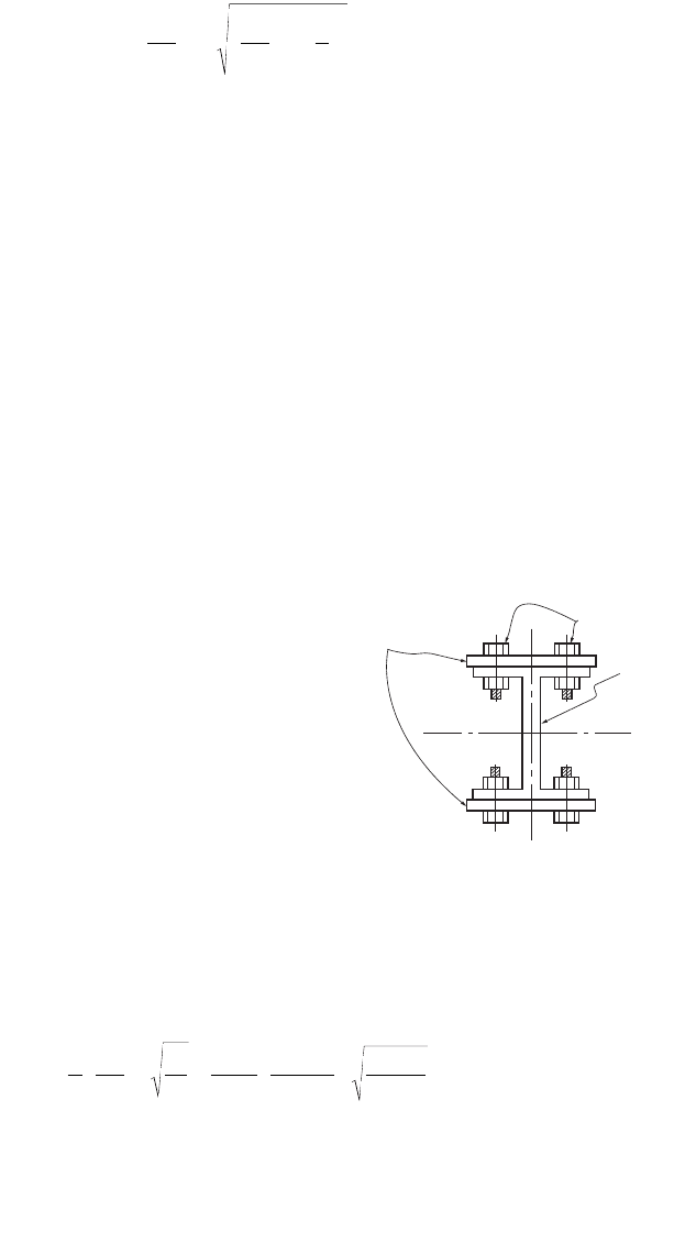
Example 48.2
Using LRFD, determine the size of a pair of cover plates to be
bolted, using fully tightened bolts, to the flanges of a W24¥229
section as shown in Fig. 48.8, so that its design strength, f
c
P
n
,
will be increased by 20%. Also determine the spacing of the
bolts along the longitudinal axis of the built-up column. The
effective lengths of the section about the major (KL)
x
and
minor (KL)
y
axes are both equal to 20 feet. A992 steel is to be
used.
Determine design strength for the W24
¥
229 section:
Since (KL)
x
= (KL)
y
and r
x
> r
y
, (KL/r)
y
will exceed (KL/r)
x
and
the design strength will be controlled by flexural buckling
about the minor axis. Using section properties, r
y
= 3.11 in.
and A = 67.2 in.
2
, obtained from the AISC-LRFD manual
[AISC, 2001], the slenderness parameter l
c
about the minor
axis can be calculated as follows:
Substituting l
c
= 1.02 into Eq. (48.17), the design strength of the section is
mo
i
KL
r
KL
r
a
r
Ê
Ë
Á
ˆ
¯
˜
=
Ê
Ë
Á
ˆ
¯
˜
+
Ê
Ë
Á
ˆ
¯
˜
2
2
FIGURE 48.8 Design of cover plates for a
compression member.
Snug-Tight Bolts
W24x229
x
y
x
Cover Plates
y
l
p
c
y
y
y
KL
r
F
E
()
=
Ê
Ë
Á
ˆ
¯
˜
=
¥
Ê
Ë
Á
ˆ
¯
˜
=
11
3 142
20 12
311
50
29 000
102
.. ,
.
cn
P
f
=
()
È
Î
Í
˘
˚
˙
=085672 0658 50 1848
102
2
... kips
.
© 2003 by CRC Press LLC