Wai-Fah Chen.The Civil Engineering Handbook
Подождите немного. Документ загружается.

48-34 The Civil Engineering Handbook, Second Edition
The remaining variables in the above equations are further defined as follows:
M
p
= F
y
Z
x
M
r
= F
L
S
x
for I-shaped sections and channels and F
yf
S
x
for solid rectangular bars and box sections
F
L
= the smaller of (F
yf
– F
r
) or F
yw
F
yf
= flange yield stress (ksi)
F
yw
= web yield stress (ksi)
F
r
= 10 ksi for rolled sections and 16.5 ksi for welded sections
F
y
= specified minimum yield stress
S
x
= elastic section modulus about the major axis
Z
x
= plastic section modulus about the major axis
I
y
= moment of inertia about the minor axis
J = torsional constant
C
w
= warping constant
E = modulus of elasticity
G = shear modulus
C
b
= 12.5M
max
/(2.5 M
max
+ 3M
A
+ 4M
B
+ 3 M
C
)
M
max
, M
A
, M
B
, and M
C
= absolute values of maximum, quarter-point, midpoint, and three-quarter
point moments, respectively, along the unbraced length of the member.
C
b
is a factor that accounts for the effect of moment gradient on the lateral torsional buckling strength
of the beam. The lateral torsional buckling strength increases for a steep moment gradient. The worst
loading case as far as lateral torsional buckling is concerned is when the beam is subjected to a uniform
moment resulting in single curvature bending. For this case, C
b
= 1. Therefore, the use of C
b
= 1 is
conservative for the design of beams.
Compact Section Members Bent about Their Minor Axes — Regardless of L
b
, the limit state will be plastic
hinge formation:
(48.43)
Noncompact Section Members Bent about Their Major Axes — For L
b
£ L¢
p
(flange or web local buckling),
(48.44)
where
(48.45)
L
p
, L
r
, M
p
, and M
r
are defined as before for compact section members.
For flange local buckling, l = b
f
/2t
f
for I-shaped members and b
f
/t
f
for channels.
l
p
and
l
r
are defined
in Table 48.8.
For web local buckling,
l
= h
c
/t
w
.
l
p
and
l
r
are defined in Table 48.8, in which b
f
is the flange width,
t
f
is the flange thickness, h
c
is twice the distance from the neutral axis to the inside face of the compression
flange less the fillet or corner radius, and t
w
is the web thickness.
For L¢
p
< L
b
£ L
r
(inelastic lateral torsional buckling), f
b
M
n
is given by Eq. (48.40), except that the
limit 0.90M
p
is to be replaced by the limit 0.90 M¢
n
.
For L
b
> L
r
(elastic lateral torsional buckling), f
b
M
n
is the same as for compact section members, as
given in Eq. (48.41) or (48.42).
bn py yy
M M F Z
f
==090 090..
bn bn p p r
p
rp
M M MMM
ff
l
l
ll
== --
()
-
-
Ê
Ë
Á
ˆ
¯
˜
È
Î
Í
Í
˘
˚
˙
˙
¢
090.
LLLL
MM
MM
pprp
pn
pr
¢
¢
=+ -
()
-
-
Ê
Ë
Á
ˆ
¯
˜
© 2003 by CRC Press LLC
Design of Steel Structures 48-35
Noncompact Section Members Bent about Their Minor Axes — Regardless of the value of L
b
, the limit
state will be either flange or web local buckling, and f
b
M
n
is given by Eq. (48.42).
Slender Element Sections — Refer to Section 48.10.
Tees and Double Angles Bent about Their Major Axes — The design flexural strength for tees and double-
angle beams with flange and web slenderness ratios less than the corresponding limiting slenderness
ratios
l
r
shown in Table 48.8 is given by
(48.46)
where
(48.47)
Use the plus sign for B if the entire length of the stem along the unbraced length of the member is in
tension. Otherwise, use the minus sign. b equals 1.5 for stems in tension and 1.0 for stems in compression.
The other variables in Eq. (48.46) are defined as before, in Eq. (48.41).
Shear Strength Criterion
For a satisfactory design, the design shear strength of the webs must exceed the factored shear acting on
the cross section, i.e.,
(48.48)
Depending on the slenderness ratios of the webs, three limit states can be identified: shear yielding,
inelastic shear buckling, and elastic shear buckling. The design shear strengths that correspond to each
of these limit states are given as follows:
For h/t
w
£ 2.45÷(E/F
yw
) (shear yielding of web),
(48.49)
For 2.45 ÷(E/F
yw
) < h/t
w
£ 3.07÷(E/F
yw
) (inelastic shear buckling of web),
(48.50)
For 3.07 ÷(E/F
yw
) < h/t
w
£ 260 (elastic shear buckling of web),
(48.51)
The variables used in the above equations are defined as follows: h is the clear distance between flanges
less the fillet or corner radius, t
w
is the web thickness, F
yw
is the yield stress of the web, A
w
= dt
w
, and d
is the overall depth of the section.
bn
y
b
y
M
EI GJ
L
BB M
f
p
b=++
()
È
Î
Í
Í
˘
˚
˙
˙
£
()
090 1 090
2
..
B
d
L
I
J
b
y
=±
Ê
Ë
Á
ˆ
¯
˜
23.
vn u
VV
f
≥
vn yww
V F A
f
=
[]
090060..
vn yww
yw
w
V F A
EF
ht
f
=
()
È
Î
Í
Í
Í
˘
˚
˙
˙
˙
090 060
245
..
.
v
n
w
w
V
A
E
ht
f
=
()
È
Î
Í
Í
˘
˚
˙
˙
090
452
2
.
.
© 2003 by CRC Press LLC
48-36 The Civil Engineering Handbook, Second Edition
Criteria for Concentrated Loads
When concentrated loads are applied normal to the flanges in planes parallel to the webs of flexural
members, the flanges and webs must be checked to ensure that they have sufficient strengths fR
n
to
withstand the concentrated forces R
u
, i.e.,
(48.52)
The design strengths for a variety of limit states are given below.
Local Flange Bending — The design strength for local flange bending is given by
(48.53)
where t
f
= the flange thickness of the loaded flange
F
yf
= the flange yield stress
The design strength in Eq. (48.53) is applicable only if the length of load across the member flange
exceeds 0.15b, where b is the member flange width. If the length of load is less than 0.15b, the limit state
of local flange bending need not be checked. Also, Eq. (48.53) shall be reduced by a factor of half if the
concentrated force is applied less than 10t
f
from the beam end.
Local Web Yielding — The design strengths for yielding of beam web at the toe of the fillet under tensile
or compressive loads acting on one or both flanges are as follows:
If the load acts at a distance from the beam end that exceeds the depth of the member,
(48.54)
If the load acts at a distance from the beam end that does not exceed the depth of the member,
(48.55)
where k = the distance from the outer face of the flange to the web toe of fillet
N = the length of bearing on the beam flange
F
yw
= the web yield stress
t
w
= the web thickness
Web Crippling — The design strengths for crippling of the beam web under compressive loads acting on
one or both flanges are as follows:
If the load acts at a distance from the beam end that exceeds half the depth of the beam,
(48.56)
If the load acts at a distance from the beam end that does not exceed half the depth of the beam and if
N/d £ 0.2,
(48.57)
If the load acts at a distance from the beam end that does not exceed half the depth of the beam and if
N/d > 0.2,
f RR
nu
≥
f R t F
nffy
≥
[]
090625
2
..
f R kNFt
nyww
=+
()
[]
100 5.
f R k N F t
nyww
=+
()
[]
100 25..
f R t
N
d
t
t
EF t
t
nw
w
f
yw f
w
=+
Ê
Ë
Á
ˆ
¯
˜
Ê
Ë
Á
ˆ
¯
˜
È
Î
Í
Í
˘
˚
˙
˙
Ï
Ì
Ô
Ó
Ô
¸
˝
Ô
˛
Ô
075 080 1 3
2
15
..
.
f R t
N
d
t
t
EF t
t
nw
w
f
yw f
w
=+
Ê
Ë
Á
ˆ
¯
˜
Ê
Ë
Á
ˆ
¯
˜
È
Î
Í
Í
˘
˚
˙
˙
Ï
Ì
Ô
Ó
Ô
¸
˝
Ô
˛
Ô
075 040 1 3
2
15
..
.
© 2003 by CRC Press LLC
Design of Steel Structures 48-37
(48.58)
where d is the overall depth of the section and t
f
is the flange thickness. The other variables are the same
as those defined in Eqs. (48.54) and (48.55).
Side Sway Web Buckling — Side sway web buckling may occur in the web of a member if a compressive
concentrated load is applied to a flange not restrained against relative movement by stiffeners or lateral
bracings. The side sway web buckling design strength for the member is as follows:
If the loaded flange is restrained against rotation about the longitudinal member axis and (h/t
w
)(l/b
f
) is
less than 2.3,
(48.59)
If the loaded flange is not restrained against rotation about the longitudinal member axis and (d
c
/t
w
)(l/b
f
)
is less than 1.7,
(48.60)
where t
f
= the flange thickness (in.)
t
w
= the web thickness (in.)
h = the clear distance between flanges less the fillet or corner radius for rolled shapes (the
distance between adjacent lines of fasteners or the clear distance between flanges when
welds are used for built-up shapes) (in.)
b
f
= the flange width (in.)
l = the largest laterally unbraced length along either flange at the point of load (in.)
C
r
= 960,000 ksi if M
u
/M
y
< 1 at the point of load or 480,000 ksi if M
u
/M
y
≥ 1 at the point of
load (M
y
is the yield moment).
Compression Buckling of the Web — This limit state may occur in members with unstiffened webs when
both flanges are subjected to compressive forces. The design strength for this limit state is
(48.61)
This design strength shall be reduced by a factor of half if the concentrated forces are acting at a distance
less than half the beam depth from the beam end. The variables in Eq. (48.61) are the same as those
defined in Eqs. (48.58) to (48.60).
Stiffeners shall be provided in pairs if any one of the above strength criteria is violated. If the local
flange bending or the local web yielding criterion is violated, the stiffener pair to be provided to carry
the excess R
u
need not extend more than one half the web depth. The stiffeners shall be welded to the
loaded flange if the applied force is tensile. They shall either bear on or be welded to the loaded flange
if the applied force is compressive. If the web crippling or the compression web buckling criterion is
violated, the stiffener pair to be provided shall extend the full height of the web. They shall be designed
as axially loaded compression members (see Section 48.4) with an effective length factor of K = 0.75 and
f R t
N
d
t
t
EF t
t
nw
w
f
yw f
w
=+-
Ê
Ë
Á
ˆ
¯
˜
Ê
Ë
Á
ˆ
¯
˜
È
Î
Í
Í
˘
˚
˙
˙
Ï
Ì
Ô
Ó
Ô
¸
˝
Ô
˛
Ô
075 040 1
4
02
2
15
.. .
.
f R
C t t
h
ht
lb
n
rwf
w
f
=+
Ê
Ë
Á
ˆ
¯
˜
È
Î
Í
Í
˘
˚
˙
˙
Ï
Ì
Ô
Ó
Ô
¸
˝
Ô
˛
Ô
085 1 04
3
2
3
..
f R
C t t
h
ht
lb
n
rwf
w
f
=
Ê
Ë
Á
ˆ
¯
˜
È
Î
Í
Í
˘
˚
˙
˙
Ï
Ì
Ô
Ó
Ô
¸
˝
Ô
˛
Ô
085 04
3
2
3
..
f R
t EF
h
n
wyw
=
È
Î
Í
Í
˘
˚
˙
˙
090
24
3
.
© 2003 by CRC Press LLC

48-38 The Civil Engineering Handbook, Second Edition
a cross section A
g
composed of the cross-sectional areas of the stiffeners, plus 25t
w
2
for interior stiffeners
and 12t
w
2
for stiffeners at member ends.
Deflection Criterion
The deflection criterion is the same as that for ASD. Since deflection is a serviceability limit state, service
(rather than factored) loads is used in deflection computations.
Continuous Beams
Continuous beams shall be designed in accordance with the criteria for flexural members given in the
preceding section. However, a 10% reduction in negative moments due to gravity loads is permitted at
the supports provided that:
1. The maximum positive moment between supports is increased by one tenth the average of the
negative moments at the supports.
2. The section is compact.
3. The lateral unbraced length does not exceed L
c
(for ASD) or L
pd
(for LRFD),
where L
c
is as defined in Eq. (48.26) and L
pd
is given by
(48.62)
in which F
y
is the specified minimum yield stress of the compression flange; M
1
/M
2
is the ratio of
smaller to larger moments within the unbraced length, taken as positive if the moments cause
reverse curvature and negative if the moments cause single curvature; and r
y
is the radius of
gyration about the minor axis.
4. The beam is not a hybrid member.
5. The beam is not made of high-strength steel.
6. The beam is continuous over the supports (i.e., not cantilevered).
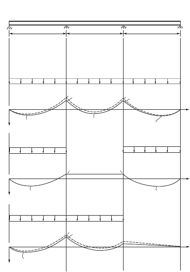
Example 48.4
Using LRFD, select the lightest W section for the three-span continuous beam shown in Fig. 48.10a to
support a uniformly distributed dead load of 1.5 k/ft (22 kN/m) and a uniformly distributed live load
of 3 k/ft (44 kN/m). The beam is laterally braced at the supports A, B, C, and D. Use A36 steel.
Load combinations:
The beam is to be designed based on the worst load combination of Table 48.3. By inspection, the load
combination 1.2D + 1.6L will control the design. Thus, the beam will be designed to support a factored
uniformly distributed dead load of 1.2 ¥ 1.5 = 1.8 k/ft and a factored uniformly distributed live load of
1.6 ¥ 3 = 4.8 k/ft.
Placement of loads:
The uniform dead load is to be applied over the entire length of the beam, as shown in Fig. 48.10b. The
uniform live load is to be applied to spans AB and CD, as shown in Fig. 48.10c, to obtain the maximum
positive moment, and it is to be applied to spans AB and BC, as shown in Fig. 48.10d, to obtain the
maximum negative moment.
Reduction of negative moment at supports:
Assuming the beam is compact and L
b
< L
pd
(we shall check these assumptions later), a 10% reduction
in support moment due to gravity load is allowed, provided that the maximum moment is increased by
L
M
M
E
F
r,
M
M
E
F
r
E
F
r,
pd
y
y
y
y
y
y
=
+
Ê
Ë
Á
ˆ
¯
˜
È
Î
Í
Í
˘
˚
˙
˙
Ê
Ë
Á
ˆ
¯
˜
+
Ê
Ë
Á
ˆ
¯
˜
È
Î
Í
Í
˘
˚
˙
˙
Ê
Ë
Á
ˆ
¯
˜
≥
Ê
Ë
Á
ˆ
¯
˜
Ï
Ì
Ô
Ô
Ó
Ô
Ô
012 0076
017 010 010
1
2
1
2
..
.. .
for I-shaped members
for solid rectangular and box sections
© 2003 by CRC Press LLC
Design of Steel Structures 48-39
one tenth the average of the negative support moments. This reduction is shown in the moment diagrams
as solid lines in Fig. 48.10b and 48.10d. (The dotted lines in these figure parts represent the unadjusted
moment diagrams.) This provision for support moment reduction takes into consideration the beneficial
effect of moment redistribution in continuous beams, and it allows for the selection of a lighter section
if the design is governed by negative moments. Note that no reduction in negative moments is made to
the case when only spans AB and CD are loaded. This is because for this load case the negative support
moments are less than the positive in-span moments.
Determination of the required flexural strength, M
u
:
Combining load cases 1 and 2, the maximum positive moment is found to be 256 kip-ft. Combining
load cases 1 and 3, the maximum negative moment is found to be 266 kip-ft. Thus, the design will be
controlled by the negative moment and M
u
= 266 kip-ft.
Beam selection:
A beam section is to be selected based on Eq. (48.38). The critical segment of the beam is span AB. For
this span, the lateral unsupported length, L
b
, is equal to 20 ft. For simplicity, the bending coefficient, C
b
,
is conservatively taken as 1. The selection of a beam section is facilitated by the use of a series of beam
charts contained in the AISC-LRFD manual [AISC, 2001]. Beam charts are plots of flexural design
strength f
b
M
n
of beams as a function of the lateral unsupported length L
b
, based on Eqs. (48.39) to
(48.41). A beam is considered satisfactory for the limit state of flexure if the beam strength curve envelopes
the required flexural strength for a given L
b
.
For the present example, L
b
= 20 ft and M
u
= 266 kip-ft; the lightest section (the first solid curve that
envelopes M
u
= 266 kip-ft for L
b
= 20 ft) obtained from the chart is a W16x67 section. Upon adding the
factored dead weight of this W16x67 section to the specified loads, the required flexural strength increases
from 266 to 269 kip-ft. Nevertheless, the beam strength curve still envelopes this required strength for
L
b
= 20 ft; therefore, the section is adequate.
FIGURE 48.10 Design of a three-span continuous beam (1 k = 4.45 kN, 1 ft = 0.305 m).
ABC
Service Dead Load = 1.5 k/ft.
Service Live Load = 3 k/ft.
D
20 ft.20 ft.
(a)
1.8 k/ft.
4.8 k/ft. 4.8 k/ft.
20 ft.
+
+
+
+
+
+
+
–
–
–
–
–
61.2
M
(k-ft)
M
(k-ft)
M
(k-ft)
194.5
194.5
4.8 k/ft.
25.2
(b) Load Case 1
(c) Load Case 2
(d) Load Case 3
72
64.8
224
201.6
152.3
96
96
72
64.8
61.2
© 2003 by CRC Press LLC
48-40 The Civil Engineering Handbook, Second Edition
Check for compactness:
For the W16¥67 section,
Therefore, the section is compact.
Check whether L
b
< L
pd
:
Using Eq. (48.62), with M
1
/M
2
= 0, r
y
= 2.46 in., and F
y
= 36 ksi, we have L
pd
= 246 in. (or 20.5 ft). Since
L
b
= 20 ft is less than L
pd
= 20.5 ft, the assumption made earlier is validated.
Check for the limit state of shear:
The selected section must satisfy the shear strength criterion of Eq. (48.48). From structural analysis, it
can be shown that maximum shear occurs just to the left of support B under load case 1 (for dead load)
and load case 3 (for live load). It has a magnitude of 81.8 kips. For the W16x67 section, h/t
w
= 35.9,
which is less than 2.45÷(E/F
yw
) = 69.5, so the design shear strength is given by Eq. (48.47). We have, for
F
yw
= 36 ksi and A
w
= dt
w
= (16.33)(0.395),
Therefore, shear is not a concern. Normally, the limit state of shear will not control, unless for short
beams subjected to heavy loads.
Check for limit state of deflection:
Deflection is a serviceability limit state. As a result, a designer should use service (not factored) loads for
deflection calculations. In addition, most beams are cambered to offset deflection caused by dead loads,
so only live loads are considered in deflection calculations. From structural analysis, it can be shown that
maximum deflection occurs in spans AB and CD when (service) live loads are placed on those two spans.
The magnitude of the deflection is 0.297 in. Assuming the maximum allowable deflection is L/360 where
L is the span length between supports, we have an allowable deflection of 20 ¥ 12/360 = 0.667 in. Since
the calculated deflection is less than the allowable deflection, deflection is not a problem.
Check for the limit state of web yielding and web crippling at points of concentrated loads:
From structural analysis, it can be shown that a maximum support reaction occurs at support B when
the beam is subjected to the loads shown as load case 1 (for dead load) and load case 3 (for live load).
The magnitude of the reaction R
u
is 157 kips. Assuming point bearing, i.e., N = 0, we have, for d = 16.33 in.,
k = 1.375 in., t
f
= 0.665 in., and t
w
= 0.395 in.,
Thus, both the web yielding and web crippling criteria are violated. As a result, we need to provide web
stiffeners or a bearing plate at support B. Suppose we choose the latter, the size of the bearing plate can
be determined by solving Eqs. (48.54) and (48.56) for N using R
u
= 157 kips. The result is N = 4.2 and
3.3 in., respectively. So, use N = 4.25 in. The width of the plate, B, should conform with the flange width,
b
f
, of the W-section. The W16¥67 section has a flange width of 10.235 in., so use B = 10.5 in. The
thickness of the bearing plate is to be calculated from the following equation [AISC, 2001]:
Flange:
b
t
<
E
F
Web:
h
t
<
E
F
f
f
y
c
w
y
2
77 038 108
35 9 3 76 106 7
=
È
Î
Í
˘
˚
˙
=
È
Î
Í
Í
˘
˚
˙
˙
=
È
Î
Í
˘
˚
˙
=
È
Î
Í
Í
˘
˚
˙
˙
.. .
.. .
vn yww u
V F A V
f
=
()
=
[]
>=
[]
090060 125 81 8.. .kips kips
Web Yielding: R < R
Web Crippling: R < R
nu
nu
f
f
= Eq. kips kips
= Eq. kips kips
46 54 97 8 157
46 56 123 157
..
.
()
=
[]
=
[]
()
=
[]
=
[]
© 2003 by CRC Press LLC
Design of Steel Structures 48-41
where R
u
= the factored concentrated load at the support (kips)
B = the width of the bearing plate (in.)
k = the distance from the web toe of the fillet to the outer surface of the flange (in.)
A = the area of bearing plate (in.
2
)
F
y
= the yield strength of the bearing plate
Substituting R
u
= 157 kips, B = 10.5 in., k = 1.375 in., A = 42 in.
2
, and F
y
= 36 ksi into the above equation,
we obtain t = 1.86 in. Therefore, use a 1
⁄
-in. plate.
For uniformity, use the same size plate at all the supports. The bearing plates are to be welded to the
supporting flange of the W section.
Use a W16¥67 section. Provide bearing plates of size 1
⁄
¥ 4 ¥ 10½–1/2 in. at the supports.
Beam Bracing
The design strength of beams that bend about their major axes depends on their lateral unsupported length
L
b
. The manner a beam is braced against out-of-plane deformation affects its design. Bracing can be provided
by various means, such as cross frames, cross beams, or diaphragms, or encasement of the beam flange in
the floor slab [Yura, 2001]. Two types of bracing systems are identified in the AISC-LRFD specification:
relative and nodal. A relative brace controls the movement of a braced point with respect to adjacent braced
points along the span of the beam. A nodal (or discrete) brace controls the movement of a braced point
without regard to the movement of adjacent braced points. Regardless of the type of bracing system used,
braces must be designed with sufficient strength and stiffness to prevent out-of-plane movement of the
beam at the braced points. Out-of-plane movement consists of lateral deformation of the beam and twisting
of cross sections. Lateral stability of beams can be achieved by lateral bracing, torsional bracing, or a
combination of the two. For lateral bracing, bracing shall be attached near the compression flange for
members bent in single curvature (except cantilevers). For cantilevers, bracing shall be attached to the tension
flange at the free end. For members bent in double curvature, bracing shall be attached to both flanges near
the inflection point. For torsional bracing, bracing can be attached at any cross-sectional location.
Stiffness Requirement for Lateral Bracing
The required brace stiffness of the bracing assembly in a direction perpendicular to the longitudinal axis
of the braced member, in the plane of buckling, is given by
(48.63)
where f = 0.75, M
u
is the required flexural strength
C
d
= 1.0 for single curvature bending and 2.0 for double curvature bending near the inflection
point
L
br
= the distance between braces
h
o
= the distance between flange centroids. L
br
can be replaced by L
q
(the maximum unbraced
length for M
u
) if L
br
< L
q
Strength Requirement for Lateral Bracing
In addition to the stiffness requirement as stipulated above, braces must be designed for a required brace
strength given by
t
RB k
AF
u
y
=
-
[]
222 2 2
2
.
b
f
f
br
ud
br o
ud
br o
MC
Lh
MC
Lh
=
Ï
Ì
Ô
Ô
Ó
Ô
Ô
4
10
for relative bracing
for nodal bracing
© 2003 by CRC Press LLC
48-42 The Civil Engineering Handbook, Second Edition
(48.64)
The terms in Eq. (48.64) are defined as in Eq. (48.63).
Stiffness Requirement for Torsional Bracing
The required bracing stiffness is
(48.65)
where
(48.66)
and
(48.67)
in which f = 0.75
L = the span length
M
u
= the required moment
n = the number of brace points within the span
E = the modulus of elasticity
I
y
= the moment of inertia of the minor axis
C
b
= the bending coefficient as defined in Section 48.5
h
o
= the distance between flange centroids
t
w
= the thickness of the beam web
t
s
= the thickness of the web stiffener
b
s
= the width of stiffener (or, for pairs of stiffeners, b
s
is the total width of stiffeners)
Strength Requirement for Torsional Bracing
The connection between a torsional brace and the beam being braced must be able to withstand a moment
given by
(48.68)
where L
br
is the distance between braces (if L
br
< L
q
; where L
q
is the maximum unbraced length for M
u
,
use L
q
). The other terms in Eq. (48.68) are defined in Eq. (48.66).
P
MC
h
MC
h
br
ud
o
ud
o
=
Ï
Ì
Ô
Ô
Ó
Ô
Ô
0 008
002
.
.
for relative bracing
for nodal bracing
b
b
b
b
Tbr
T
T
=
-
Ê
Ë
Á
ˆ
¯
˜
≥
1
0
sec
b
f
f
T
u
yb
u
yb
LM
nEI C
M
EI C
=
Ï
Ì
Ô
Ô
Ó
Ô
Ô
24
24
2
2
2
2
.
.
for nodal bracing
for continuous bracing
b
sec
.
.
.
=
+
Ê
Ë
Á
ˆ
¯
˜
Ï
Ì
Ô
Ô
Ó
Ô
Ô
33
15
12 12
33
12
33
2
E
h
ht tb
Et
h
o
ow ss
w
o
for nodal bracing
for continuous bracing
M
ML
nC L
Tbr
u
bbr
=
0 024.
© 2003 by CRC Press LLC

Design of Steel Structures 48-43
Example 48.5
Design an I-shaped cross beam 12 ft (3.7 m) in length to be used as lateral braces to brace a 30-ft (9.1-m)-
long simply supported W30¥90 girder at every third point. The girder was designed to carry a moment
of 8000 kip-in. (904 kN-m). A992 steel is used.
Because a brace is provided at every third point, L
br
= 10 ft = 120 in. M
u
= 8000 kip-in., as stated. C
d
=
1 for single curvature bending. h
o
= d – t
f
= 29.53 – 0.610 = 28.92 in. for the W30¥90 section. Substituting
these values into Eqs. (48.63) and (48.64) for nodal bracing, we obtain b
br
= 30.7 kips/in. and P
br
=
5.53 kips.
Because the cross beam will be subject to compression, its slenderness ratio, l/r, should not exceed
200. Let us try the smallest-size W section , a W4¥13 section with A = 3.83 in.
2
, r
y
= 1.00 in., and f
c
P
n
=
25 kips.
Since all criteria are satisfied, the W4¥13 section is adequate.
Use W4¥13 as cross beams to brace the girder.
48.6 Combined Flexure and Axial Force
When a member is subject to the combined action of bending and axial force, it must be designed to
resist stresses and forces arising from both bending and axial actions. While a tensile axial force may
induce a stiffening effect on the member, a compressive axial force tends to destabilize the member, and
the instability effects due to member instability (P-d effect) and frame instability (P-D effect) must be
properly accounted for. The P-d effect arises when the axial force acts through the lateral deflection of
the member relative to its chord. The P-D effect arises when the axial force acts through the relative
displacements of the two ends of the member. Both effects tend to increase member deflection and
moment; so they must be considered in the design. A number of approaches are available in the literature
to handle these so-called P-delta effects (see, for example, Galambos [1998] and Chen and Lui [1991]).
The design of members subject to combined bending and axial force is facilitated by the use of interaction
equations. In these equations the effects of bending and axial actions are combined in a certain manner
to reflect the capacity demand on the member.
Design for Combined Flexure and Axial Force
Allowable Stress Design
The interaction equations are as follows:
If the axial force is tensile,
(48.69)
,
EA
l
P
l
r
n
y
Stiffness =
()()
¥
=>
=>
=
¥
=<
29000 3 83
12 12
771 30 7
3
2
44
.
.
Strength, 25 kips 5.5 kips
Slenderness,
112
1.00
1 200
c
kips in. kips in.
f
f
F
f
F
f
F
a
t
bx
bx
by
by
++£10.
© 2003 by CRC Press LLC