Wai-Fah Chen.The Civil Engineering Handbook
Подождите немного. Документ загружается.

48-24 The Civil Engineering Handbook, Second Edition
Determine design strength for the built-up section:
The built-up section is expected to possess a design strength that is 20% in excess of the design strength
of the W24¥229 section, so
Determine size of the cover plates:
After cover plates are added, the resulting section is still doubly symmetric. Therefore, the overall failure
mode is still flexural buckling. For flexural buckling about the minor axis (y-y), no modification to (KL/r)
is required, since the buckling axis is perpendicular to the plane of contact of the component shapes, so
no relative movement between the adjoining parts is expected. However, for flexural buckling about the
major (x-x) axis, modification to (KL/r) is required, since the buckling axis is parallel to the plane of
contact of the adjoining structural shapes and slippage between the component pieces will occur. We
shall design the cover plates assuming flexural buckling about the minor axis will control and check for
flexural buckling about the major axis later.
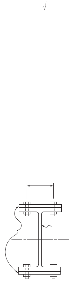
A W24¥229 section has a flange width of 13.11 in.; so, as a trial, use cover plates with widths of 14 in.,
as shown in Fig. 48.8. Denoting t as the thickness of the plates, we have
and
Assuming (l)
y,built-up
is less than 1.5, one can substitute the above expression for l
c
in Eq. (48.17). With
f
c
P
n
equals 2218, we can solve for t. The result is t ª 3/8 in. Backsubstituting t = 3/8 into the above
expression, we obtain (l)
c,built-up
= 0.975, which is indeed <1.5. So, try 14 ¥ 3/8 in. cover plates.
Check for local buckling:
For the I section:
For the cover plates, if 3/4-in. diameter bolts are used and assuming an edge distance of 2 in., the width
of the plate between fasteners will be 13.11 – 4 = 9.11 in. Therefore, we have
Since the width–thickness ratios of all component shapes do not exceed the limiting width–thickness
ratio for local buckling, local buckling is not a concern.
f
cn
r eqd
P
()
=
()( )
=
¢
120 1848 2218. kips
r
II
AA
t
t
y
built-up
y
W-shape
y
plates
W-shape plates
()
=
()
+
()
+
=
+
+
651 457 3
67 2 28
.
.
l
p
c
y,built-up
y,built-up
y
KL
r
F
E
+t
+t
()
=
Ê
Ë
Á
ˆ
¯
˜
=
1
317
67 2 28
651 457 3
.
.
.
Flange:
b
t
<
E
F
Web:
h
t
<
E
F
f
fy
c
wy
2
38 056 056
29 000
50
13 5
22 5 1 49 1 49
29 000
50
35 9
=
È
Î
Í
Í
˘
˚
˙
˙
==
È
Î
Í
Í
˘
˚
˙
˙
=
È
Î
Í
˘
˚
˙
==
È
Î
Í
Í
˘
˚
˙
˙
.. .
,
.
.. .
,
.
b
t
<
E
F
y
==
È
Î
Í
˘
˚
˙
==
È
Î
Í
Í
˘
˚
˙
˙
911
38
24 3 1 40 1 40
29 000
50
33 7
.
.. .
,
.
© 2003 by CRC Press LLC
Design of Steel Structures 48-25
Check for flexural buckling about the major (x-x) axis:
Since the built-up section is doubly symmetric, the governing buckling mode will be flexural buckling
regardless of the axes. Flexural buckling will occur about the major axis if the modified slenderness ratio
(KL/r)
m
about the major axis exceeds (KL/r)
y
. Therefore, as long as (KL/r)
m
is less than (KL/r)
y
, buckling
will occur about the minor axis and flexural buckling about the major axis will not control. In order to
arrive at an optimal design, we shall determine the longitudinal fastener spacing, a, such that the modified
slenderness ratio (KL/r)
m
about the major axis will be equal to (KL/r)
y
. That is, we shall solve for a from
the equation
In the above equation, (KL/r)
x
is the slenderness ratio about the major axis of the built-up section and
r
i
is the least radius of gyration of the component shapes, which in this case is the cover plate.
Substituting (KL/r)
x
= 21.7 and r
i
= r
cover plate
= ÷(I/A)
cover plate
= ÷[(3/8)
2
/12] = 0.108 into the above
equation, we obtain a = 7.62 in. Since (KL) = 20 ft, we shall use a = 6 in. for the longitudinal spacing
of the fasteners.
Check for component element buckling between adjacent fasteners:
so the component element buckling criterion is not a concern.
Use 14 ¥ 3/8 in. cover plates bolted to the flanges of the W24¥229 section by 3/4-in.-diameter fully
tightened bolts spaced 6 in. longitudinally.
Column Bracing
The design strength of a column can be increased if lateral braces are provided at intermediate points
along its length in the buckled direction of the column. The AISC-LRFD specification [AISC, 1999]
identifies two types of bracing systems for columns. A relative bracing system is one in which the
movement of a braced point with respect to other adjacent braced points is controlled, e.g., the diagonal
braces used in buildings. A nodal (or discrete) brace system is one in which the movement of a braced
point with respect to some fixed point is controlled, e.g., the guy wires of guyed towers. A bracing system
is effective only if the braces are designed to satisfy both stiffness and strength requirements. The following
equations give the required stiffness and strength for the two bracing systems:
Required braced stiffness:
(48.26)
where f = 0.75
P
u
= the required compression strength of the column
L
br
= the distance between braces
mx
i
y
KL
r
KL
r
a
r
KL
r
Ê
Ë
Á
ˆ
¯
˜
=
Ê
Ë
Á
ˆ
¯
˜
+
Ê
Ë
Á
ˆ
¯
˜
È
Î
Í
Í
Í
˘
˚
˙
˙
˙
=
Ê
Ë
Á
ˆ
¯
˜
=
È
Î
Í
Í
˘
˚
˙
˙
2
2
73 8.
Ka
r
KL
r
i
y
=
¥
=
È
Î
Í
˘
˚
˙
ª
Ê
Ë
Á
ˆ
¯
˜
=
()
=
È
Î
Í
Í
˘
˚
˙
˙
16
0 108
55 6
3
4
3
4
73 8 55 4
.
...
b
f
f
cr
u
br
u
br
P
L
P
L
=
Ï
Ì
Ô
Ô
Ó
Ô
Ô
2
8
for relative bracing
for nodal bracing
© 2003 by CRC Press LLC

48-26 The Civil Engineering Handbook, Second Edition
If L
br
is less than L
q
(the maximum unbraced length for P
u
), L
br
can be replaced by L
q
in the above
equations.
Required braced strength:
(48.27)
where P
u
is defined as in Eq. (48.26).
48.5 Flexural Members
Depending on the width–thickness ratios of the component elements, steel sections used as flexural
members are classified as compact, noncompact, and slender element sections. Compact sections are
sections that can develop the cross section plastic moment (M
p
) under flexure and sustain that moment
through a large hinge rotation without fracture. Noncompact sections are sections that either cannot
develop the cross section full plastic strength or cannot sustain a large hinge rotation at M
p
, probably
due to local buckling of the flanges or web. Slender elements are sections that fail by local buckling of
component elements long before M
p
is reached. A section is considered compact if all its component
elements have width–thickness ratios less than a limiting value (denoted as l
p
in LRFD). A section is
considered noncompact if one or more of its component elements have width–thickness ratios that fall
in between l
p
and l
y
. A section is considered a slender element if one or more of its component elements
have width–thickness ratios that exceed l
r
. Expressions for l
p
and l
r
are given in the Table 48.8.
In addition to the compactness of the steel section, another important consideration for beam design
is the lateral unsupported (unbraced) length of the member. For beams bent about their strong axes, the
failure modes, or limit states, vary depending on the number and spacing of lateral supports provided
to brace the compression flange of the beam. The compression flange of a beam behaves somewhat like
a compression member. It buckles if adequate lateral supports are not provided in a phenomenon called
lateral torsional buckling. Lateral torsional buckling may or may not be accompanied by yielding, depend-
ing on the lateral unsupported length of the beam. Thus, lateral torsional buckling can be inelastic or
elastic. If the lateral unsupported length is large, the limit state is elastic lateral torsional buckling. If the
lateral unsupported length is smaller, the limit state is inelastic lateral torsional buckling. For compact
section beams with adequate lateral supports, the limit state is full yielding of the cross section (i.e.,
plastic hinge formation). For noncompact section beams with adequate lateral supports, the limit state
is flange or web local buckling. For beams bent about their weak axes, lateral torsional buckling will not
occur, so the lateral unsupported length has no bearing on the design. The limit states for such beams
will be formation of a plastic hinge if the section is compact and flange or web local buckling if the
section is noncompact.
Beams subjected to high shear must be checked for possible web shear failure. Depending on the
width–thickness ratio of the web, failure by shear yielding or web shear buckling may occur. Short, deep
beams with thin webs are particularly susceptible to web shear failure. If web shear is of concern, the use
of thicker webs or web reinforcements such as stiffeners is required.
Beams subjected to concentrated loads applied in the plane of the web must be checked for a variety
of possible flange and web failures. Failure modes associated with concentrated loads include local flange
bending (for a tensile concentrated load), local web yielding (for a compressive concentrated load), web
crippling (for a compressive load), sidesway web buckling (for a compressive load), and compression
buckling of the web (for a compressive load pair). If one or more of these conditions is critical, transverse
stiffeners extending at least one half of the beam depth (use full depth for compressive buckling of the
web) must be provided adjacent to the concentrated loads.
P
P
P
br
u
u
=
Ï
Ì
Ô
Ó
Ô
0 004
001
.
.
for relative bracing
for nodal bracing
© 2003 by CRC Press LLC

Design of Steel Structures 48-27
Long beams can have deflections that may be too excessive, leading to problems in serviceability. If
deflection is excessive, the use of intermediate supports or beams with higher flexural rigidity is required.
The design of flexural members should satisfy, at the minimum, the following criteria: (1) flexural
strength criterion, (2) shear strength criterion, (3) criteria for concentrated loads, and (4) deflection
criterion. To facilitate beam design, a number of beam tables and charts are given in the AISC manuals
[AISC, 1989, 2001] for both allowable stress and load and resistance factor design.
Flexural Member Design
Allowable Stress Design
Flexural Strength Criterion
The computed flexural stress, f
b
, shall not exceed the allowable flexural stress, F
b
, given as follows. In all
equations, the minimum specified yield stress, F
y
, can not exceed 65 ksi.
TABLE 48.8 l
p
and l
r
for Members under Flexural Compression
Component Element
Width–Thickness
Ratio
a
l
p
l
r
Flanges of I-shaped rolled beams
and channels
b/t 0.38÷(E/F
y
) 0.83÷(E/F
L
)
b
Flanges of I-shaped hybrid or
welded beams
b/t 0.38÷(E/F
yf
) for nonseismic application
0.31÷(E/F
yf
) for seismic application
0.95÷[E/(F
L
/k
c
)]
c
Flanges of square and
rectangular box and hollow
structural sections of uniform
thickness; flange cover plates
and diaphragm plates between
lines of fasteners or welds
b/t 0.939÷(E/F
y
) for plastic analysis 1.40/÷(E/F
y
)
Unsupported width of cover
plates perforated with a
succession of access holes
b/t NA 1.86÷(E/F
y
)
Legs of single-angle struts; legs of
double-angle struts with
separators; unstiffened
elements
b/t NA 0.45/÷(E/F
y
)
Stems of tees d/t NA 0.75÷(E/F
y
)
Webs in flexural compression h
c
/t
w
3.76÷(E/F
y
) for nonseismic application
3.05÷(E/F
y
) for seismic application
5.70÷(E/F
y
)
d
Webs in combined flexural and
axial compression
h
c
/t
w
For P
u
/f
b
P
y
£ 0.125:
3.76(1 – 2.75P
u
/f
b
P
y
)÷( E/F
y
) for
nonseismic application
3.05(1 – 1.54P
u
/f
b
P
y
)÷( E/F
y
) for seismic
application
For P
u
/f
b
P
y
> 0.125:
1.12(2.33 – P
u
/f
b
P
y
)÷(E/F
y
)
≥1.49÷(E/F
y
)
5.70(1 – 0.74P
u
/f
b
P
y
)÷(E/F
y
)
Circular hollow sections D/t 0.07E/F
y
0.31E/F
y
Note: NA = not applicable, E = modulus of elasticity, F
y
= minimum specified yield strength, F
L
= smaller of (F
yf
– F
r
) or F
yw
,
F
yf
= flange yield strength, F
yw
= web yield strength, F
r
= flange compressive residual stress (10 ksi for rolled shapes, 16.5 ksi for
welded shapes), k
c
is as defined in the footnote of Table 48.4, f
b
= 0.90, P
u
= factored axial force, P
y
= A
g
F
y
, D = outside diameter,
t = wall thickness.
a
See Fig. 48.5 for definitions of b, h
c
, and t.
b
For ASD, this limit is 0.56÷(E/F
y
).
c
For ASD, this limit is 0.56÷ E/(F
yf
/k
c
), where k
c
= 4.05/(h/t)
0.46
if h/t > 70; otherwise, k
c
= 1.0.
d
For ASD, this limit is 4.46÷(E/F
b
); F
b
= allowable bending stress.
© 2003 by CRC Press LLC
48-28 The Civil Engineering Handbook, Second Edition
Compact-Section Members Bent about Their Major Axes — For L
b
£ L
c
,
(48.28)
where L
c
is the smaller of {76b
f
/÷F
y
, 20,000/(d/A
f
)F
y
} for I and channel shapes and equal to [1950 +
1200(M
1
/M
2
)](b/F
y
) ≥ 1200(b/F
y
) for box sections and rectangular and circular tubes in which b
f
is the
flange width (in.), d is the overall depth of section (ksi), A
f
is the area of compression flange (in.
2
), b is
the width of cross section (in.), and M
1
/M
2
is the ratio of the smaller to larger moments at the ends of
the unbraced length of the beam (M
1
/M
2
is positive for reverse curvature bending and negative for single
curvature bending).
For the above sections to be considered as compact, in addition to having the width–thickness ratios
of their component elements falling within the limiting value of l
p
, shown in Table 48.8, the flanges of
the sections must be continuously connected to the webs. For box-shaped sections, the following require-
ments must also be satisfied: the depth-to-width ratio should not exceed 6 and the flange-to-web thickness
ratio should not exceed 2.
For L
b
> L
c
, the allowable flexural stress in tension is given by
(48.29)
and the allowable flexural stress in compression is given by the larger value calculated from Eqs. (48.30)
and (48.31). Equation (48.30) normally controls for deep, thin-flanged sections where warping restraint
torsional resistance dominates, and Eq. (48.31) normally controls for shallow, thick-flanged sections
where St. Venant torsional resistance dominates.
(48.30)
(48.31)
where l = the distance between cross sections braced against twist or lateral displacement of the
compression flange (in.)
r
T
= the radius of gyration of a section comprising the compression flange plus one third of
the compression web area, taken about an axis in the plane of the web (in.)
A
f
= the compression flange area (in.
2
)
d = the depth of cross section (in.)
C
b
= 12.5M
max
/(2.5M
max
+ 3M
A
+ 4M
B
+ 3M
C
)
M
max
, M
A
, M
B
, and M
C
= the absolute values of the maximum moment, quarter-point moment,
midpoint moment, and three-quarter point moment, respectively, along the unbraced
length of the member.
(For simplicity in design, C
b
can conservatively be taken as unity.)
It should be cautioned that Eqs. (48.30) and (48.31) are applicable only to I and channel shapes with
an axis of symmetry in and loaded in the plane of the web. In addition, Eq. (48.31) is applicable only if
the compression flange is solid and approximately rectangular in shape, and its area is not less than the
tension flange.
F F
by
= 066.
FF
by
= 060.
F
F lr
C
F F ,
C
F
l
r
<
C
F
C
lr
F ,
l
r
C
F
b
yT
b
yy
b
yT
b
y
b
T
y
T
b
y
=
-
()
¥
È
Î
Í
Í
˘
˚
˙
˙
££
()
£ ≥
Ï
Ì
Ô
Ô
Ô
Ô
Ó
Ô
Ô
Ô
2
3
1530 10
060
102 000 510 000
170 000
060
510 000
2
3
2
.
,,
,
.
,
if
if
ÔÔ
F
C
ld A
F
b
b
f
y
=£
12 000
060
,
.
© 2003 by CRC Press LLC
Design of Steel Structures 48-29
Compact Section Members Bent about Their Minor Axes — Since lateral torsional buckling will not occur
for bending about the minor axes, regardless of the value of L
b
, the allowable flexural stress is
(48.32)
Noncompact Section Members Bent about Their Major Axes — For L
b
£ L
c
,
(48.33)
where L
c
is defined as in Eq. (48.28).
For L
b
> L
c
, F
b
is given in Eqs. (48.29) to (48.31).
Noncompact Section Members Bent about Their Minor Axes — Regardless of the value of L
b
,
(48.34)
Slender Element Sections — Refer to the Section 48.10.
Shear Strength Criterion
For practically all structural shapes commonly used in constructions, the shear resistance from the flanges
is small compared to the webs. As a result, the shear resistance for flexural members is normally deter-
mined on the basis of the webs only. The amount of web shear resistance is dependent on the width–thick-
ness ratio h/t
w
of the webs. If h/t
w
is small, the failure mode is web yielding. If h/t
w
is large, the failure
mode is web buckling. To avoid web shear failure, the computed shear stress, f
v
, shall not exceed the
allowable shear stress, F
v
, given by
(48.35)
where C
v
= 45,000k
v
/[F
y
(h/t
w
)
2
] if C
v
£ 0.8 and [190/(h/t
w
)]÷(k
v
/F
y
) if C
v
> 0.8
k
v
= 4.00 + 5.34/(a/h)
2
if a/h £ 1.0 and 5.34 + 4.00/( a/h)
2
if a/h > 1.0
t
w
= the web thickness (in.)
a = the clear distance between transverse stiffeners (in.)
h = the clear distance between flanges at the section under investigation (in.)
Criteria for Concentrated Loads
Local Flange Bending — If the concentrated force that acts on the beam flange is tensile, the beam flange
may experience excessive bending, leading to failure by fracture. To preclude this type of failure, transverse
stiffeners are to be provided opposite the tension flange, unless the length of the load when measured
across the beam flange is less than 0.15 times the flange width, or if the flange thickness, t
f
, exceeds
(48.36)
where P
bf
= the computed tensile force multiplied by 5/3 if the force is due to live and dead loads only
or by 4/3 if the force is due to live and dead loads in conjunction with wind or earthquake
loads (kips)
F
y
= the specified minimum yield stress (ksi ).
FF
by
= 075.
FF
by
= 060.
FF
by
= 060.
F
F
h
t
F
C
F F
h
t
F
v
y
w
y
v
yy
w
y
=
£
£>
Ï
Ì
Ô
Ô
Ó
Ô
Ô
040
380
289
040
380
.
.
.
if
if
04.
P
F
bf
y
© 2003 by CRC Press LLC
48-30 The Civil Engineering Handbook, Second Edition
Local Web Yielding — To prevent local web yielding, the concentrated compressive force, R, should not
exceed 0.66R
n
, where R
n
is the web yielding resistance given in Eq. (48.54) or (48.55), whichever applies.
Web Crippling — To prevent web crippling, the concentrated compressive force, R, should not exceed
0.50R
n
, where R
n
is the web crippling resistance given in Eq. (48.56), (48.57), or (48.58), whichever applies.
Sidesway Web Buckling — To prevent sidesway web buckling, the concentrated compressive force, R,
should not exceed R
n
, where R
n
is the sidesway web buckling resistance given in Eq. (48.59) or (48.60),
whichever applies, except the term C
r
t
w
3
t
f
/h
2
is replaced by 6,800 t
w
3
/h.
Compression Buckling of the Web — When the web is subjected to a pair of concentrated forces acting
on both flanges, buckling of the web may occur if the web depth clear of fillet, d
c
, is greater than
(48.37)
where t
w
= the web thickness
F
y
= the minimum specified yield stress
P
bf
= as defined in Eq. (48.36)
Deflection Criterion
Deflection is a serviceability consideration. Since most beams are fabricated with a camber that somewhat
offsets the dead load deflection, consideration is often given to deflection due to live load only. For beams
supporting plastered ceilings, the service live load deflection preferably should not exceed L/360, where
L is the beam span. A larger deflection limit can be used if due considerations are given to ensure the
proper functioning of the structure.
Example 48.3
Using ASD, determine the amount of increase in flexural capacity of a W24¥55 section bent about its
major axis if two 7 ¥ 1/2 in. (178 ¥ 13 mm) cover plates are bolted to its flanges, as shown in Fig. 48.9.
The beam is laterally supported at every 5-ft (1.52-m) interval. Use A36 steel. Specify the type, diameter,
and longitudinal spacing of the bolts used if the maximum shear to be resisted by the cross section is
100 kips (445 kN).
Section properties:
A W24¥55 section has the following section properties: b
f
= 7.005 in., t
f
= 0.505 in., d = 23.57 in., t
w
=
0.395 in., I
x
= 1350 in.
4
, and S
x
= 114 in.
3
FIGURE 48.9 Beam section with cover plates.
4100
3
t F
P
wy
bf
y
x
W24 × 55
7" × 1/2"
Plates
4 in.
© 2003 by CRC Press LLC
Design of Steel Structures 48-31
Check compactness:
Refer to Table 48.8; assuming that the transverse distance between the two bolt lines is 4 in., we have
Therefore, the section is compact.
Determine the allowable flexural stress, F
b
:
Since the section is compact and the lateral unbraced length, L
b
= 60 in., is less than L
c
= 83.4 in., the
allowable bending stress from Eq. (48.28) is 0.66F
y
= 24 ksi.
Determine section modulus of the beam with cover plates:
Determine flexural capacity of the beam with cover plates:
Since the flexural capacity of the beam without cover plates is
the increase in flexural capacity is 68.4%.
Determine diameter and longitudinal spacing of bolts:
From Chapter 46, “Mechanics of Materials,” the relationship between the shear flow, q, the number of
bolts per shear plane, n, the allowable bolt shear stress, F
v
, the cross-sectional bolt area, A
b
, and the
longitudinal bolt spacing, s, at the interface of two component elements of a combination section is given
by
Substituting n = 2 and q = VQ/I = (100)[(7)(1/2)(12.035)]/2364 = 1.78 k/in. into the above equation,
we have
Beam flanges
b
t
<
E
F
Beam web
d
t
<
E
F
Cover plates <
E
F
f
fy
wy
y
2
694 038 10 8
59 7 3 76 107
4
12
80939 26 7
=
È
Î
Í
Í
˘
˚
˙
˙
=
È
Î
Í
Í
˘
˚
˙
˙
=
È
Î
Í
˘
˚
˙
=
È
Î
Í
Í
˘
˚
˙
˙
=
È
Î
Í
˘
˚
˙
=
È
.. .
..
..
ÎÎ
Í
Í
˘
˚
˙
˙
S
I
c
+
x, combination section
x, combination section
==
+
Ê
Ë
Á
ˆ
¯
˜
()
()
+
()
()
()
È
Î
Í
˘
˚
˙
Ê
Ë
Á
ˆ
¯
˜
=
1350 2
1
12
712 71212 035
23 57
2
1
2
192
3
2
3
.
.
in
MS F
x, combination section x, combination section b
==
()()
=192 24 4608 k-in
MS F
xxb
==
()()
=114 24 2736 k-in
n F A
s
q
vb
=
F A
s
vb
= 09. kin.
© 2003 by CRC Press LLC
48-32 The Civil Engineering Handbook, Second Edition
If 1/2-in.-diameter A325-N bolts are used, we have A
b
= p(1/2)
2
/4 = 0.196 in.
2
and F
v
= 21 ksi (from
Table 48.12), from which s can be solved from the above equation to be 4.57 in. However, for ease of
installation, use s = 4.5 in.
In calculating the section properties of the combination section, no deduction is made for the bolt
holes in the beam flanges or cover plates; this is allowed provided that the following condition is satisfied
where F
y
and F
u
= the minimum specified yield strength and tensile strength, respectively
A
fn
= the net flange area
A
fg
= the gross flange area. For this problem,
so the use of the gross cross-sectional area to compute section properties is justified. In the event that
the condition is violated, cross-sectional properties should be evaluated using an effective tension flange
area A
fe
given by
So, use 1/2-in.-diameter A325-N bolts spaced 4.5 in. apart longitudinally in two lines 4 in. apart to
connect the cover plates to the beam flanges.
Load and Resistance Factor Design
Flexural Strength Criterion
Flexural members must be designed to satisfy the flexural strength criterion of
(48.38)
where f
b
M
n
is the design flexural strength and M
u
is the required strength. The design flexural strength
is determined as follows:
Compact Section Members Bent about Their Major Axes — For L
b
£ L
p
(plastic hinge formation),
(48.39)
For L
p
£ L
b
£ L
r
(inelastic lateral torsional buckling),
(48.40)
05 06..F A F A
ufn yfg
≥
Beam Flanges
F A
FA
Cover Plates
FA
FA
ufn
yfg
ufn
yfg
05 0558 7005 2120505 87 9
36 7 005 0 505
58 7 2 12 12
... ..kips
> 0.6 0.6 . . 76.4 kips
0.5 0.5 87 kips
> 0.6 0.6
=
()
-¥
()
()
=
[]
=
()( )()
=
[]
=
()
--
()()
=
[]
= 3636 7 1 2
()()
()
=
[]
75.6 kips
A
F
F
A
fe
u
y
fn
=
5
6
bn u
MM
f
≥
bn p
MM
f
= 090.
bn b p p r
bp
rp
p
M C MMM
LL
LL
M
f
=--
()
-
-
Ê
Ë
Á
ˆ
¯
˜
È
Î
Í
Í
˘
˚
˙
˙
£090 090..
© 2003 by CRC Press LLC
Design of Steel Structures 48-33
For L
b
> L
r
(elastic lateral torsional buckling),
For I-shaped members and channels:
(48.41)
For solid rectangular bars and symmetric box sections:
(48.42)
The variables used in the above equations are defined as follows: L
b
is the lateral unsupported length of
the member and L
p
and L
r
are the limiting lateral unsupported lengths given in the following table:
Structural Shape L
p
L
r
I-shaped sections
and channels
1.76r
y
/÷(E/F
yf
)
where
r
y
= radius of gyration about minor
axis
E = modulus of elasticity
F
yf
= flange yield strength
[r
y
X
1
/F
L
]{÷[1 + ÷(1 + X
2
F
L
2
)]}
where
r
y
= radius of gyration about minor axis (in.)
X
1
= (p/S
x
)÷(EGJA/2)
X
2
= (4C
w
/I
y
)(S
x
/GJ)
2
F
L
= smaller of (F
yf
– F
r
) or F
yw
F
yf
= flange yield stress (ksi)
F
yw
= web yield stress (ksi)
F
r
= 10 ksi for rolled shapes and 16.5 ksi for
welded shapes
S
x
= elastic section modulus about the major
axis (in.
3
) (use S
xc
, the elastic section
modulus about the major axis with
respect to the compression flange if the
compression flange is larger than the
tension flange)
I
y
= moment of inertia about the minor axis
(in.
4
)
J= torsional constant (in.
4
)
C
w
= warping constant (in.
6
)
E = modulus of elasticity (ksi)
Solid rectangular
bars and
symmetric box
sections
[0.13r
y
E÷(JA)]/M
p
where
r
y
= radius of gyration about minor
axis
E = modulus of elasticity
J = torsional constant
A = cross-sectional area
M
p
= plastic moment capacity = F
y
Z
x
F
y
= yield stress
Z
x
= plastic section modulus about the
major axis
[2r
y
E÷(JA)]/M
r
where
r
y
= radius of gyration about minor axis
J = torsional constant
A = cross-sectional area
M
r
= F
yf
S
x
F
y
= yield stress
F
yf
= flange yield strength
S
x
= elastic section modulus about the major
axis
Note: The L
p
values given in this table are valid only if the bending coefficient C
b
is equal to unity. If C
b
> 1, the value
of L
p
can be increased. However, using the L
p
expressions given above for C
b
> 1 will give a conservative value for the
flexural design strength.
bn b
b
y
b
yw p
M C
L
EI GJ
E
L
IC M
f
pp
=+
Ê
Ë
Á
ˆ
¯
˜
È
Î
Í
Í
Í
˘
˚
˙
˙
˙
£090 090
2
..
bn b
by
p
MC
JA
Lr
M
f
=£090
57 000
090.
,
.
© 2003 by CRC Press LLC