Wai-Fah Chen.The Civil Engineering Handbook
Подождите немного. Документ загружается.

48-44 The Civil Engineering Handbook, Second Edition
where f
a
= the computed axial tensile stress
f
bx
and f
by
= the computed bending tensile stresses about the major and minor axes, respectively
F
t
= the allowable tensile stress (see Section 48.3)
F
bx
and F
by
= the allowable bending stresses about the major and minor axes, respectively (see
Section 48.5).
If the axial force is compressive,
Stability requirement:
(48.70)
Yield requirement:
(48.71)
However, if the axial force is small (when f
a
/F
a
£ 0.15), the following interaction equation can be used
in lieu of the above equations.
(48.72)
The terms in the Eqs. (48.70) to (48.72) are defined as follows: f
a
, f
bx
, and f
by
are the computed axial
compressive stress, the computed bending stress about the major axis, and the computer bending stress
about the minor axis, respectively. These stresses are to be computed based on a first-order analysis: F
y
is the minimum specified yield stress; F¢
ex
and F¢
ey
are the Euler stresses about the major and minor axes
(p
2
E/(Kl/r)
x
and p
2
E/(Kl/r)
y
), respectively, divided by a factor of safety of 23/12; and C
m
is a coefficient
to account for the effect of moment gradient on member and frame instabilities (C
m
is defined in the
following section). The other terms are defined as in Eq. (48.69)
The terms in brackets in Eq. (48.70) are moment magnification factors. The computed bending stresses
f
bx
and f
by
are magnified by these magnification factors to account for the P-delta effects in the member.
Load and Resistance Factor Design
Doubly or singly symmetric members subject to combined flexure and axial force shall be designed in
accordance with the following interaction equations:
For P
u
/
f
P
n
≥ 0.2,
(48.73)
For P
u
/fP
n
< 0.2,
(48.74)
where, if P is tensile, P
u
is the factored tensile axial force, P
n
is the design tensile strength (see Section 48.3),
M
u
is the factored moment (preferably obtained from a second-order analysis), M
n
is the design flexural
f
F
C
f
F
f
F
C
f
F
f
F
a
a
mx
a
ex
bx
bx
my
a
ey
by
by
+
-
¢
È
Î
Í
Í
Í
Í
˘
˚
˙
˙
˙
˙
+
-
¢
È
Î
Í
Í
Í
Í
˘
˚
˙
˙
˙
˙
£
() ()
.
11
10
f
F
+
f
F
+
f
F
a
y
bx
bx
by
by
066
10
.
.£
f
F
f
F
f
F
a
a
bx
bx
by
by
++£10.
P
P
M
M
M
M
u
n
ux
bnx
uy
bny
f
ff
++
Ê
Ë
Á
ˆ
¯
˜
£
8
9
10.
P
P
M
M
M
M
u
n
ux
bnx
uy
bny
2
10
f
ff
++
Ê
Ë
Á
ˆ
¯
˜
£ .
© 2003 by CRC Press LLC
Design of Steel Structures 48-45
strength (see Section 48.5), f = f
t
= resistance factor for tension = 0.90, and f
b
= resistance factor for
flexure = 0.90. If P is compressive, P
u
is the factored compressive axial force, P
n
is the design compressive
strength (see Section 48.4), M
u
is the required flexural strength (see discussion below), M
n
is the design
flexural strength (see Section 48.5), f = f
c
= resistance factor for compression = 0.85, and f
b
= resistance
factor for flexure = 0.90.
The required flexural strength M
u
shall be determined from a second-order elastic analysis. In lieu of
such an analysis, the following equation may be used
(48.75)
where M
nt
= the factored moment in a member, assuming the frame does not undergo lateral transla-
tion (see Fig. 48.11)
M
lt
= the factored moment in a member as a result of lateral translation (see Fig. 48.11)
B
1
= C
m
/(1 – P
u
/P
e
) ≥ 1.0 and is the P-d moment magnification factor
P
e
= p
2
EI/(KL)
2
, with K £ 1.0 in the plane of bending
C
m
=a coefficient to account for moment gradient (see discussion below)
B
2
= 1/[1 – (SP
u
D
oh
/SHL)] or B
2
= 1/[1 – (SP
u
/SP
e
)
SP
u
= the sum of all factored loads acting on and above the story under consideration
D
oh
= the first-order interstory translation
SH = the sum of all lateral loads acting on and above the story under consideration
L = the story height
P
e
= p
2
EI/(KL)
2
For end-restrained members that do not undergo relative joint translation and are not subject to
transverse loading between their supports in the plane of bending, C
m
is given by
where M
1
/M
2
is the ratio of the smaller to larger member end moments. The ratio is positive if the
member bends in reverse curvature and negative if the member bends in single curvature.
For end-restrained members that do not undergo relative joint translation and are subject to transverse
loading between their supports in the plane of bending
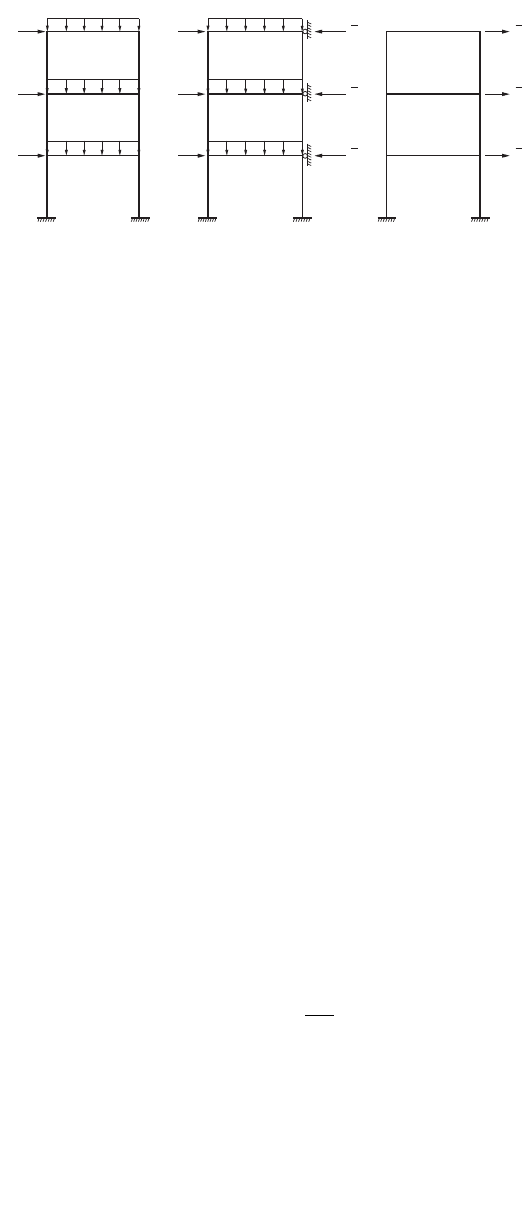
FIGURE 48.11 Calculation of M
nt
and M
lt
.
H
3
H
2
H
1
H
3
H
2
=
H
1
Original frame Nonsway frame
analysis for M
nt
Sway frame analysis
for M
lt
(a)
(b) (c)
w
3
w
2
w
1
w
3
w
2
w
1
H
3
H
2
H
1
H
3
H
2
H
1
+
MB MB M
ubtlt
=+
12
C
M
M
m
=-
Ê
Ë
Á
ˆ
¯
˜
06 04
1
2
..
C
m
= 085.
© 2003 by CRC Press LLC

48-46 The Civil Engineering Handbook, Second Edition
For unrestrained members that do not undergo relative joint translation and are subject to transverse
loading between their supports in the plane of bending
Although Eqs. (48.73) and (48.74) can be used directly for the design of beam-columns by using trial
and error or by the use of design aids [Aminmansour, 2000], the selection of trial sections is facilitated
by rewriting the interaction equations of Eqs. (48.73) and (48.74) into the so-called equivalent axial load
form:
For P
u
/
f
c
P
n
> 0.2,
(48.76)
For P
u
/f
c
P
n
£ 0.2,
(48.77)
where b =1/f
c
P
n
m = 8/9 f
b
M
nx
n = 8/9 f
b
M
ny
Numerical values for b, m, and n are provided in the AISC manual [AISC, 2001]. The advantage of
using Eqs. (48.76) and (48.77) for preliminary design is that the terms on the left-hand side of the
inequality can be regarded as an equivalent axial load, (P
u
)
eff
, thus allowing the designer to take advantage
of the column tables provided in the manual for selecting trial sections.
48.7 Biaxial Bending
Members subjected to bending about both principal axes (e.g., purlins on an inclined roof) should be
design for biaxial bending. Since both the moment about the major axis M
ux
and the moment about the
minor axis M
uy
create flexural stresses over the cross section of the member, the design must take into
consideration these stress combinations.
Design for Biaxial Bending
Allowable Stress Design
The following interaction equation is often used for the design of beams subject to biaxial bending:
(48.78)
where M
x
and M
y
= the service load moments about the major and minor beam axes, respectively
S
x
and S
y
= the elastic section moduli about the major and minor axes, respectively
F
y
= the specified minimum yield stress.
Example 48.6
Using ASD, select a W section to carry dead load moments M
x
= 20 k-ft (27 kN-m) and M
y
= 5 k-ft
(6.8 kN-m) and live load moments M
x
= 50 k-ft (68 kN-m) and M
y
= 15 k-ft (20 kN-m). Use A992 steel.
C
m
= 100.
bP mM nM
uuxuy
++£10.
b
P
mM nM
u
ux uy
2
9
8
9
8
10++£.
ff F
M
S
M
S
F
bx by y
x
x
y
y
y
+£ + £060 060.. or
© 2003 by CRC Press LLC

Design of Steel Structures 48-47
Calculate service load moments:
Select section:
Substituting the above service load moments into Eq. (48.78), we have
For W sections with a depth below 14 in. the value of S
x
/S
y
normally falls in the range of 3 to 8, and for
W sections with a depth above 14 in. the value of S
x
/S
y
normally falls in the range of 5 to 12. Assuming
S
x
/S
y
= 10, we have from the above equation, S
x
≥ 108 in.
3
. Using the Allowable Stress Design Selection
Ta ble in the AISC-ASD manual, let’s try a W24¥55 section (S
x
= 114 in.
3
, S
y
= 8.30 in.
3
). For the W24¥55
section,
The next lightest section is W21¥62 (S
x
= 127 in.
3
, S
y
= 13.9 in.
3
). For this section,
Therefore, use a W21¥62 section.
Load and Resistance Factor Design
To avoid distress at the most severely stressed point, the following equation for the limit state of yielding
must be satisfied:
(48.79)
where f
un
= M
ux
/S
+ M
uy
/S
y
is the flexural stress under factored loads
S
x
and S
y
= the elastic section moduli about the major and minor axes, respectively
f
b
= 0.90
F
y
= the specified minimum yield stress
In addition, the limit state for lateral torsional buckling about the major axis should also be checked, i.e.,
(48.80)
f
b
M
nx
is the design flexural strength about the major axis (see Section 48.5).
To facilitate design for biaxial bending, Eq. (48.79) can be rearranged to give
(48.81)
In the above equation, d is the overall depth and b
f
is the flange width of the section. The approximation
(S
x
/S
y
) ª (3.5d/b
f
) was suggested by Gaylord et al. [1992] for doubly symmetric I-shaped sections.
xx, dead x, live
yydead y live
MM M
MM M
=+=+=
=+=+=
20 50 70 k-ft
515 20 k-ft
,,
70 12 20 12
06050
¥
+
¥
£
()
+£
SS
S
S
S
xy
x
y
x
.or, 840 240 30
840 240
114
830
4136 30 30 114 3420+=
È
Î
Í
˘
˚
˙
>=
()
=
[]
\
.
NG
S
x
840 240
127
13 9
3033 30 30 127 3810+=
È
Î
Í
˘
˚
˙
<=
()
=
[]
\
S
x
.
OK
f F
un b y
£
f
bnx ux
MM
f
≥
S
M
F
M
F
S
S
M
F
M
F
d
b
x
ux
by
uy
by
x
y
ux
by
uy
by f
≥ +
Ê
Ë
Á
ˆ
¯
˜
ª+
Ê
Ë
Á
ˆ
¯
˜
ff ff
35.
© 2003 by CRC Press LLC

48-48 The Civil Engineering Handbook, Second Edition
48.8 Combined Bending, Torsion, and Axial Force
Members subjected to the combined effect of bending, torsion, and axial force should be designed to
satisfy the following limit states:
Yielding under normal stress:
(48.82)
where f = 0.90
F
y
= the specified minimum yield stress
f
un
= the maximum normal stress determined from an elastic analysis under factored loads
Yielding under shear stress:
(48.83)
where f = 0.90
F
y
= the specified minimum yield stress
f
uv
= the maximum shear stress determined from an elastic analysis under factored loads
Buckling:
(48.84)
where f
c
F
cr
= f
c
P
n
/A
g
, in which f
c
P
n
is the design compressive strength of the member (see Section
on 48.4) and A
g
is the gross cross-section area
f
un
and f
uv
= the normal and shear stresses, respectively, as defined in Eqs. (48.82) and (48.83).
48.9 Frames
Frames are designed as a collection of structural components such as beams, beam-columns (columns),
and connections. According to the restraint characteristics of the connections used in the construction,
frames can be designed as type I (rigid framing), type II (simple framing), or type III (semirigid framing)
in ASD or as fully restrained (rigid) and partially restrained (semirigid) in LRFD:
The design of rigid frames necessitates the use of connections capable of transmitting the full or a
significant portion of the moment developed between the connecting members. The rigidity of
the connections must be such that the angles between intersecting members should remain
virtually unchanged under factored loads.
The design of simple frames is based on the assumption that the connections provide no moment
restraint to the beam insofar as gravity loads are concerned, but these connections should have
an adequate capacity to resist wind moments.
The design of semirigid frames is permitted upon evidence of the connections to deliver a predicable
amount of moment restraint. Over the past two decades, a tremendous amount of work has been
published in the literature on semirigid connections and frame behavior (see, for example, Chen
[1987, 2000], Council on Tall Buildings and Urban Habitat [1993], Chen et al. [1996], and Faella
et al. [2000]). However, because of the vast number of semirigid connections that can exhibit an
appreciable difference in joint behavior, no particular approach has been recommended by any
building specifications as of this writing. The design of semirigid or partially restrained frames
relies on sound engineering judgment by the designer.
f Ff
yun
≥
f Ff
yuv
06.
()
≥
ccr un
uv
ccr
Ff
Ff
f
f
≥
≥
or , whichever is applicable
© 2003 by CRC Press LLC
Design of Steel Structures 48-49
Semirigid and simple framings often incur inelastic deformation in the connections. The connections
used in these constructions must be proportioned to possess sufficient ductility to avoid overstress of
the fasteners or welds.
Regardless of the types of constructions used, due consideration must be given to account for member
and frame instability (P-d and P-D) effects either by the use of a second-order analysis or by other means,
such as moment magnification factors or notional loads [ASCE, 1997]. The end-restrained effect on a
member should also be accounted for by the use of the effective length factor K.
Frame Design
Frames can be designed as side sway inhibited (braced) or side sway uninhibited (unbraced). In side sway
inhibited frames, frame drift is controlled by the presence of a bracing system (e.g., shear walls, diagonal,
cross, or K braces, etc.). In side sway uninhibited frames, frame drift is limited by the flexural rigidity
of the connected members and diaphragm action of the floors. Most side sway uninhibited frames are
designed as type I or type FR frames using moment connections. Under normal circumstances, the
amount of interstory drift under service loads should not exceed h/500 to h/300, where h is the story
height. A higher value of interstory drift is allowed only if it does not create serviceability concerns.
Beams in side sway inhibited frames are often subject to high axial forces. As a result, they should be
designed as beam-columns using beam-column interaction equations. Furthermore, vertical bracing
systems should be provided for braced multistory frames to prevent vertical buckling of the frames under
gravity loads.
When designing members of a frame, a designer should consider a variety of loading combinations and
load patterns, and the members are designed for the most severe load cases. Preliminary sizing of members
can be achieved by the use of simple behavioral models such as the simple beam model, cantilever column
model, and portal and cantilever method of frame analysis (see, for example, Rossow [1996]).
Frame Bracing
The subject of frame bracing is discussed in a number of references (see, for example, SSRC [1993] and
Galambos [1998]). According to the LRFD specification [AISC, 1999] the required story or panel bracing
shear stiffness in side sway inhibited frames is
(48.85)
where f = 0.75, SP
u
is the sum of all factored gravity load acting on and above the story or panel
supported by the bracing
L = the story height or panel spacing
The required story or panel bracing force is
(48.86)
48.10 Plate Girders
Plate girders are built-up beams. They are used as flexural members to carry extremely large lateral loads.
A flexural member is considered as a plate girder if the width–thickness ratio of the web, h
c
/t
w
, exceeds
760/÷F
b
(F
b
is the allowable flexural stress) according to ASD or l
r
(see Table 48.8) according to LRFD.
Because of the large web slenderness, plate girders are often designed with transverse stiffeners to reinforce
the web and to allow for postbuckling (shear) strength (i.e., tension field action) to develop. Table 48.9
b
f
cr
u
P
L
=
Â
2
PP
br u
=
Â
0 004.
© 2003 by CRC Press LLC
48-50 The Civil Engineering Handbook, Second Edition
summarizes the requirements for transverse stiffeners for plate girders based on the web slenderness ratio
h/t
w
. Two types of transverse stiffeners are used for plate girders: bearing stiffeners and intermediate
stiffeners. Bearing stiffeners are used at unframed girder ends and at concentrated load points where the
web yielding or web crippling criterion is violated. Bearing stiffeners extend the full depth of the web
from the bottom of the top flange to the top of the bottom flange. Intermediate stiffeners are used when
the width–thickness ratio of the web, h/t
w
, exceeds 260, when the shear criterion is violated, or when
tension field action is considered in the design. Intermediate stiffeners need not extend the full depth of
the web, but they must be in contact with the compression flange of the girder.
Normally, the depths of plate girder sections are so large that the simple beam theory, postulating that
plane sections before bending remain plane after bending, does not apply. As a result, a different set of
design formulas for plate girders is required.
Plate Girder Design
Allowable Stress Design
Allowable Bending Stress
The maximum bending stress in the compression flange of the girder computed using the flexure formula
shall not exceed the allowable value, F¢
b
, given by
(48.87)
where F
b
= the applicable allowable bending stress, as discussed in Section 48.5 (ksi)
R
PG
= the plate girder stress reduction factor, 1 – 0.0005(A
w
/A
f
)(h/t
w
– 760/÷F
b
) £ 1.0
R
e
= the hybrid girder factor, [12 + (A
w
/A
f
)(3a – a
3
)]/[12 + 2(A
w
/A
f
)] £ 1.0 (R
e
= 1 for
nonhybrid girders)
A
w
= the area of web
A
f
= the area of compression flange
a = 0.60F
yw
/F
b
£ 1.0
F
yw
= the yield stress of web
Allowable Shear Stress
The allowable shear stress without tension field action is the same as that for beams given in Eq. (48.35).
The allowable shear stress with tension field action is given by
(48.88)
TA BLE 48.9 We b Stiffeners Requirements
Range of Web Slenderness Stiffener Requirements
Plate girder can be designed without web stiffeners
Plate girder must be designed with web stiffeners; the spacing of stiffeners, a,
can exceed 1.5h; the actual spacing is determined by the shear criterion
Plate girder must be designed with web stiffeners; the spacing of stiffeners, a,
cannot exceed 1.5h
Note: a = clear distance between stiffeners, h = clear distance between flanges when welds are used or the distance
between adjacent lines of fasteners when bolts are used, t
w
= web thickness, F
yf
= compression flange yield stress (ksi).
h
t
w
£ 260
260
048
16 5
<£
+
()
h
t
E
FF
w
yf yf
.
.
048
16 5
11 7
.
.
.
E
FF
h
t
E
F
yf yf
wyf
+
()
<£
¢
=FF R R
bbPGe
F
F
C
C
ah
F
v
y
v
v
y
=+
-
+
()
È
Î
Í
Í
Í
˘
˚
˙
˙
˙
£
289
1
115 1
040
2
.
.
.
© 2003 by CRC Press LLC
Design of Steel Structures 48-51
Note that tension field action can be considered in the design only for nonhybrid girders. If tension field
action is considered, transverse stiffeners must be provided and spaced at a distance so that the computed
average web shear stress, f
v
, obtained by dividing the total shear by the web area, does not exceed the
allowable shear stress, F
v
, given by Eq. (48.88). In addition, the computed bending tensile stress in the
panel where tension field action is considered can not exceed 0.60F
y
, or (0.825 – 0.375f
v
/F
v
)F
y
where f
v
is the computed average web shear stress, and F
v
is the allowable web shear stress given in Eq. (48.88).
The shear transfer criterion given by Eq. (48.91) must also be satisfied.
Transverse Stiffeners
Tr ansverse stiffeners must be designed to satisfy the following criteria:
Moment of inertia criterion:
With reference to an axis in the plane of the web, the moment of inertia of the stiffeners (in square
inches) shall satisfy the condition
(48.89)
where h is the clear distance between flanges (in inches).
Area criterion:
The total area of the stiffeners (in square inches) shall satisfy the condition
(48.90)
where C
v
= the shear buckling coefficient as defined in Eq. (48.35)
a = the stiffeners’ spacing
h = the clear distance between flanges
t
w
= the web thickness
Y = the ratio of web yield stress to stiffener yield stress
D = 1.0 for stiffeners furnished in pairs, 1.8 for single-angle stiffeners, and 2.4 for single-plate
stiffeners.
Shear transfer criterion:
If tension field action is considered, the total shear transfer (in kips/in.) of the stiffeners shall not be less
than
(48.91)
where F
yw
= the web yield stress (ksi)
h = the clear distance between flanges (in.)
The value of f
vs
can be reduced proportionally if the computed average web shear stress, f
v
, is less than
F
v
given in Eq. (48.88).
Load and Resistance Factor Design
Flexural Strength Criterion
Doubly or singly symmetric single-web plate girders loaded in the plane of the web should satisfy the
flexural strength criterion of Eq. (48.38). The plate girder design flexural strength is given by:
I
h
st
≥
Ê
Ë
Á
ˆ
¯
˜
4
50
A
C
a
h
ah
ah
YDht
st
v
w
≥
-
-
()
+
()
È
Î
Í
Í
Í
˘
˚
˙
˙
˙
1
2
1
2
2
fh
F
vs
yw
=
Ê
Ë
Á
ˆ
¯
˜
3
340
© 2003 by CRC Press LLC
48-52 The Civil Engineering Handbook, Second Edition
For the limit state of tension flange yielding,
(48.92)
For the limit state of compression flange buckling,
(48.93)
where S
xt
= the section modulus referred to the tension flange, I
x
/c
t
S
xc
= the section modulus referred to the compression flange, I
x
/c
c
I
x
= the moment of inertia about the major axis
c
t
= the distance from the neutral axis to the extreme fiber of the tension flange
c
c
= the distance from the neutral axis to the extreme fiber of the compression flange
R
PG
= the plate girder bending strength reduction factor, 1 – a
r
[h
c
/t
w
–
5.70÷(E/F
cr
)]/[1200 +
300a
r
] £ 1.0
R
e
= the hybrid girder factor, [12 + a
r
(3m – m
3
)]/[12 + 2a
r
] £ 1.0 (R
e
= 1 for nonhybrid girders)
a
r
= the ratio of web area to compression flange area
m = the ratio of web yield stress to flange yield stress or ratio of web yield stress to F
cr
F
yt
= the tension flange yield stress; and F
cr
is the critical compression flange stress calculated
as follows:
Limit State Range of Slenderness F
cr
(ksi)
Flange local
buckling
F
yf
Lateral
torsional
buckling
F
yf
Note: k
c
= 4/÷(h/t
w
), 0.35 £ k
c
£ 0.763, b
f
= compression flange width, t
f
= compression flange thickness,
L
b
= lateral unbraced length of the girder, r
T
= ÷[(t
f
b
f
3
/12 + h
c
t
w
3
/72)/(b
f
t
f
+ h
c
t
w
/6)], h
c
= twice the distance
from the neutral axis to the inside face of the compression flange less the fillet, t
w
= web thickness, F
yf
=
yield stress of compression flange (ksi), C
b
= bending coefficient (see Section 48.5).
bn xteyt
M S R F
f
=
[]
090.
bn xcPG e cr
M S R R F
f
=
[]
090.
b
t
E
F
f
fyf
2
038£ .
038
2
135..
E
F
b
t
E
Fk
yf
f
fyfc
<£
F
b
t
E
F
E
Fk
E
F
F
yf
f
fyf
yf c yf
yf
1
1
2
2
038
135 038
-
-
-
Ê
Ë
Á
Á
Á
Á
Á
ˆ
¯
˜
˜
˜
˜
˜
È
Î
Í
Í
Í
Í
Í
Í
˘
˚
˙
˙
˙
˙
˙
˙
£
.
..
b
t
E
Fk
f
fyfc
2
135> .
26 200
2
2
, k
b
t
c
f
f
Ê
Ë
Á
ˆ
¯
˜
L
r
E
F
b
tyf
£ 176.
176 444..
E
F
L
r
E
F
yf
b
Tyf
<£
CF
L
r
E
F
E
F
E
F
F
byf
b
Tyf
yf yf
yf
1
1
2
176
444 176
-
-
-
Ê
Ë
Á
Á
Á
Á
Á
ˆ
¯
˜
˜
˜
˜
˜
È
Î
Í
Í
Í
Í
Í
Í
˘
˚
˙
˙
˙
˙
˙
˙
£
.
..
L
r
E
F
b
Tyf
> 444.
286 000
2
, C
L
r
b
b
T
Ê
Ë
Á
ˆ
¯
˜
© 2003 by CRC Press LLC
Design of Steel Structures 48-53
F
cr
must be calculated for both flange local buckling and lateral torsional buckling. The smaller value of
F
cr
is used in Eq. (48.93).
The plate girder bending strength reduction factor R
PG
is a factor to account for the nonlinear flexural
stress distribution along the depth of the girder. The hybrid girder factor is a reduction factor to account
for the lower yield strength of the web when the nominal moment capacity is computed assuming a
homogeneous section made entirely of the higher yield stress of the flange.
Shear Strength Criterion
Plate girders can be designed with or without the consideration of tension field action. If tension field
action is considered, intermediate web stiffeners must be provided and spaced at a distance a such that
a/h is smaller than 3 or [260/(h/t
w
)]
2
, whichever is smaller. Also, one must checked the flexure–shear
interaction of Eq. (48.96), if appropriate. Consideration of tension field action is not allowed if (1) the
panel is an end panel, (2) the plate girder is a hybrid girder, (3) the plate girder is a web-tapered girder,
or (4) a/h exceeds 3 or [260/(h/t
w
)]
2
, whichever is smaller.
The design shear strength, f
v
V
n
, of a plate girder is determined as follows:
If tension field action is not considered:
f
v
V
n
is the same as those for beams given in Eqs. (48.49) to (48.51).
If tension field action is considered and h/t
w
£ 1.10÷(k
v
E/F
yw
):
(48.94)
If h/t
w
>1.10÷(k
v
E/F
yw
):
(48.95)
where k
v
=5 + 5/(a/h)
2
(k
v
shall be taken as 5.0 if a/h exceeds 3.0 or [260/(h/t
w
)]
2
, whichever is smaller)
A
w
= dt
w
(where d is the section depth and t
w
is the web thickness)
F
yw
= the web yield stress
C
v
= the shear coefficient, calculated as follows:
Flexure–Shear Interaction
Plate girders designed for tension field action must satisfy the flexure–shear interaction criterion in
regions where 0.60fV
n
£ V
u
£ fV
n
and 0.75fM
n
£ M
u
£ fM
n
:
(48.96)
where f = 0.90.
Range of h/t
w
C
v
vn w yw
V A F
f
=
[]
090 060..
vn w yw v
v
V A FC
C
ah
f
=+
-
+
()
Ê
Ë
Á
Á
ˆ
¯
˜
˜
È
Î
Í
Í
Í
˘
˚
˙
˙
˙
090 060
1
115 1
2
..
.
110 137..
kE
F
h
t
kE
F
v
yw w
v
yw
££
110. kE F
ht
vyw
w
h
t
kE
F
w
v
yw
> 137.
151
2
. kE
ht F
v
wyw
()
M
M
V
V
u
n
u
n
ff
+£0 625 1 375..
© 2003 by CRC Press LLC