Wai-Fah Chen.The Civil Engineering Handbook
Подождите немного. Документ загружается.

50-26 The Civil Engineering Handbook, Second Edition
Spacing Limitations for Shear Reinforcement.
ACI 11.5.4.1 sets the maximum spacing of vertical stirrups as the smaller of (3/4)h or 24 in. The maximum
spacing of inclined stirrups is such that a 45° line extending from midheight of the member to the tension
reinforcement will intercept at least one stirrup.
If V
s
exceeds 4 b
w
d, the maximum allowable spacings are reduced to one-half of those just described.
50.6 Development of Reinforcement
The development length, l
d
, is the shortest length of bar in which the bar stress can increase from zero
to the yield strength, f
y
. If the distance from a point where the bar stress equals f
y
to the end of the bar
is less than the development length, the bar will pull out of the concrete. Development lengths are different
for tension and compression.
Development of Bars in Tension
ACI Fig. R12.2 gives a flow chart for determining development length. The steps are outlined below.
The basic tension development lengths have been found to be (ACI 12.2.2). For no. 11 and smaller
bars and deformed wire:
(50.99)
For no. 14 bars:
(50.100)
For no. 18 bars:
(50.101)
where is not to be taken greater than 100 psi.
The development length, l
d
, is computed as the product of the basic development length and modifi-
cation factors given in ACI 12.2.3, 12.2.4, and 12.2.5. The development length obtained from ACI 12.2.2
and 12.2.3.1 through 12.2.3.5 shall not be less than
(50.102)
as given in ACI 12.2.3.6.
The length computed from ACI 12.2.2 and 12.2.3 is then multiplied by factors given in ACI 12.2.4
and 12.2.5. The factors given in ACI 12.2.3.1 through 12.2.3.3 and 12.2.4 are required, but the factors in
ACI 12.2.3.4, 12.2.3.5, and 12.2.5 are optional.
The development length is not to be less than 12 inches (ACI 12.2.1).
Development of Bars in Compression
The basic compression development length is (ACI 12.3.2)
(50.103)
¢
f
c
l
Af
f
db
by
c
=
¢
004.
l
f
f
db
y
c
=
¢
0 085.
I
f
f
db
y
c
=
¢
0 125.
¢
f
c
003. df
f
by
c
¢
l
df
f
df
db
by
c
by
=
¢
≥
002
0 003
.
.
© 2003 by CRC Press LLC
Structural Concrete Design 50-27
The development length, l
d
, is found as the product of the basic development length and applicable
modification factors given in ACI 12.3.3.
The development length is not to be less than 8 inches (ACI 12.3.1).
Development of Hooks in Tension
The basic development length for a hooked bar with f
y
= 60,000 psi as (ACI 12.5.2)
(50.104)
The development length, l
dh
, is found as the product of the basic development length and applicable
modification factors given in ACI 12.5.3.
The development length of the hook is not to be less than 8 bar diameters or 6 inches (ACI 12.5.1).
Hooks are not to be used to develop bars in compression.
Splices, Bundled Bars, and Web Reinforcement
Splices
Tension Lap Splices.
ACI 12.15 distinguishes between two types of tension lap splices depending on the amount of reinforce-
ment provided and the fraction of the bars spliced in a given length — see ACI Table R12.15.2. The splice
lengths for each splice class are as follows:
Class A splice : 1.0l
d
Class B splice : 1.3l
d
where l
d
is the tensile development length as computed in ACI 12.2 without the modification factor for
excess reinforcement given in ACI 12.2.5. The minimum splice length is 12 inches.
Lap splices are not to be used for bars larger than no. 11 except at footing to column joints and for
compression lap splices of no. 14 and no. 18 bars with smaller bars (ACI 12.14.2.1). The center-to-center
distance between two bars in a lap splice cannot be greater than one-fifth the required lap splice length
with a maximum of 6 inches (ACI 12.14.2.3). ACI 21.3.2.3 requires that tension lap splices of flexural
reinforcement in beams resisting seismic loads be enclosed by hoops or spirals.
Compression Lap Splices.
The splice length for a compression lap splice is given in ACI 12.16.1 as
(50.105)
(50.106)
but not less than 12 inches. For f ¢
c
less than 3000 psi, the lap length must be increased by one-third.
When different size bars are lap spliced in compression, the splice length is to be the larger of:
1. Compression splice length of the smaller bar, or
2. Compression development length of larger bar.
Compression lap splices are allowed for no. 14 and no. 18 bars to no. 11 or smaller bars (ACI 12.16.2).
End-Bearing Splices.
End-bearing splices are allowed for compression only where the compressive stress is transmitted by
bearing of square cut ends held in concentric contact by a suitable device. According to ACI 12.16.4.2
l
d
f
db
b
c
=
¢
1200
lfdf
syby
=£0 0005 60 000., for psi
lfdf
syby
=-
()
>0 0009 24 60 000., for psi
© 2003 by CRC Press LLC
50-28 The Civil Engineering Handbook, Second Edition
bar ends must terminate in flat surfaces within 1½° of right angles to the axis of the bars and be fitted
within 3° of full bearing after assembly. End-bearing splices are only allowed in members containing
closed ties, closed stirrups, or spirals.
Welded Splices or Mechanical Connections.
Bars stressed in tension or compression may be spliced by welding or by various mechanical connections.
ACI 12.14.3, 12.15.3, 12.15.4, and 12.16.3 govern the use of such splices. For further information see
Reinforced Concrete Design, by Chu-Kia Wang and Charles G. Salmon [1985].
Bundled Bars
The requirements of ACI 12.4.1. specify that the development length for bundled bars be based on that
for the individual bar in the bundle, increased by 20% for a three-bar bundle and 33% for a four-bar
bundle. ACI 12.4.2 states that “a unit of bundled bars shall be treated as a single bar of a diameter derived
from the equivalent total area” when determining the appropriate modification factors in ACI 12.2.3 and
12.2.4.3.
Web Reinforcement
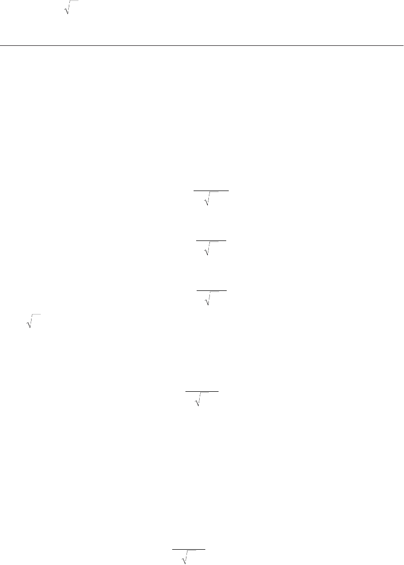
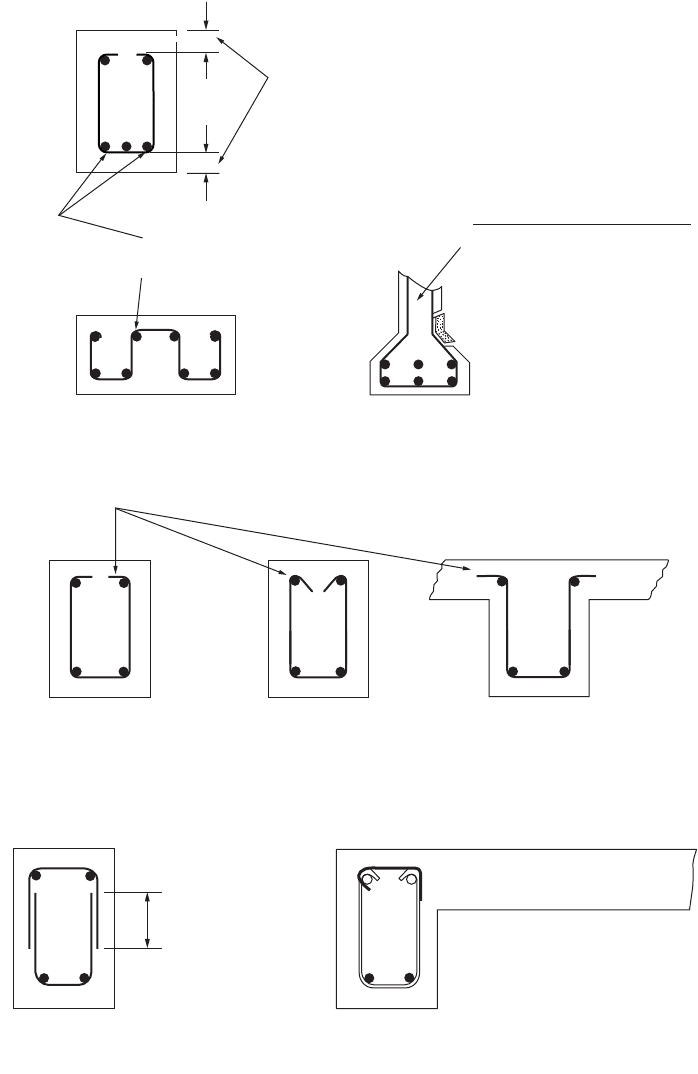
ACI 12.13.1 requires that the web reinforcement be as close to the compression and tension faces as cover
and bar-spacing reinforcements permit. The ACI Code requirements for stirrup anchorage are illustrated
in Fig. 50.4.
(a) ACI 12.13.3. requires that each bend away from the ends of a stirrup enclose a longitudinal bar,
as seen in Fig. 50.a(4).
(b) For no. 5 or D31 wire stirrups and smaller with any yield strength and for no. 6, 7, and 8 bars
with a yield strength of 40,000 psi or less, ACI 12.13.2.1 allows the use of a standard hook around
longitudinal reinforcement, as shown in Fig. 50.4(b).
(c) For no. 6, 7, and 8 stirrups with f
y
greater than 40,000 psi, ACI 12.13.2.2 requires a standard hook
around a longitudinal bar plus an embedment between midheight of the member and the outside
end of the hook of at least 0.01d
b
f
y
/.
(d) Requirements for welded wire fabric forming U stirrups are given in ACI 12.13.2.3.
(e) Pairs of U stirrups that form a closed unit shall have a lap length of 1.3l
d
as shown in Fig. 50.4(c).
This type of stirrup has proven unsuitable in seismic areas.
(f) Requirements for longitudinal bars bent to act as shear reinforcement are given in ACI 12.13.4.
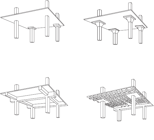
50.7 Two-Way Systems
Definition
When the ratio of the longer to the shorter spans of a floor panel drops below 2, the contribution of the
longer span in carrying the floor load becomes substantial. Since the floor transmits loads in two
directions, it is defined as a two-way system, and flexural reinforcement is designed for both directions.
Two-way systems include flat plates, flat slabs, two-way slabs, and waffle slabs (see Fig. 50.5). The choice
between these different types of two-way systems is largely a matter of the architectural layout, magnitude
of the design loads, and span lengths. A flat plate is simply a slab of uniform thickness supported directly
on columns, generally suitable for relatively light loads. For larger loads and spans, a flat slab becomes
more suitable with the column capitals and drop panels providing higher shear and flexural strength. A
slab supported on beams on all sides of each floor panel is generally referred to as a two-way slab. A
waffle slab is equivalent to a two-way joist system or may be visualized as a solid slab with recesses in
order to decrease the weight of the slab.
¢
f
c
© 2003 by CRC Press LLC
Structural Concrete Design 50-29
FIGURE 50.4 Stirrup detailing requirements. (Source: Wang and Salmon, 1985.)
Stirrups as close to compression and
tension faces as cover and spacing
requirements permit.
Not permitted
Since tension in the stirrup
will straighten the bend,
pulling the shaded piece off.
Between anchored ends, each bend
shall enclose a longitudinal bar.
(a) General requirements.
Standard stirrup hook, ACI Sec. 7.1.3, Must enclose a bar, ACI Sec. 12.13.2.1
(b) Stirrup anchorage requirements for No. 5 and smaller bars as per ACI Secs.
7.1.3 and 12.13.2.1.
Not less than 1.3
d
(c) Stirrup anchorage as
per ACI Sec. 12.13.5.
(d) Two piece closed stirrup
—Beams with torsion of compression
reinforcement. ACI Secs. 7.11 and 11.6.7.3.
© 2003 by CRC Press LLC
50-30 The Civil Engineering Handbook, Second Edition
Design Procedures
The ACI Code [ACI Committee 318, 1992] states that a two-way slab system “may be designed by any
procedure satisfying conditions of equilibrium and geometric compatibility if shown that the design
strength at every section is at least equal to the required strength.… and that all serviceability conditions,
including specified limits on deflections, are met” (p. 204). There are a number of possible approaches
to the analysis and design of two-way systems based on elastic theory, limit analysis, finite element analysis,
or combination of elastic theory and limit analysis. The designer is permitted by the ACI Code to adopt
any of these approaches provided that all safety and serviceability criteria are satisfied. In general, only
for cases of a complex two-way system or unusual loading would a finite element analysis be chosen as
the design approach. Otherwise, more practical design approaches are preferred. The ACI Code details
two procedures — the direct design method and the equivalent frame method — for the design of floor
systems with or without beams. These procedures were derived from analytical studies based on elastic
theory in conjunction with aspects of limit analysis and results of experimental tests. The primary
difference between the direct design method and equivalent frame method is in the way moments are
computed for two-way systems.
The yield-line theory is a limit analysis method devised for slab design. Compared to elastic theory,
the yield-line theory gives a more realistic representation of the behavior of slabs at the ultimate limit
state, and its application is particularly advantageous for irregular column spacing. While the yield-line
method is an upper-bound limit design procedure, strip method is considered to give a lower-bound
design solution. The strip method offers a wide latitude of design choices and it is easy to use; these are
often cited as the appealing features of the method.
Some of the earlier design methods based on moment coefficients from elastic analysis are still favored
by many designers. These methods are easy to apply and give valuable insight into slab behavior; their
use is especially justified for many irregular slab cases where the preconditions of the direct design method
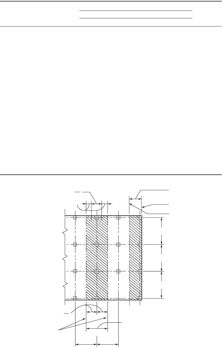
are not met or when column interaction is not significant. Table 50.7 lists the moment coefficients taken
from method 2 of the 1963 ACI Code. As in the 1989 code, two-way slabs are divided into column strips
and middle strips as indicated by Fig. 50.6, where l
1
and l
2
are the center-to-center span lengths of the
FIGURE 50.5 Tw o-way systems.
(a) Flat Plate (b) Flat Slab
(c) Two-Way Slab (d) Waffle Slab
© 2003 by CRC Press LLC
Structural Concrete Design 50-31
TA BLE 50.7 Elastic Moment Coefficients for Two-Way Slabs
Moments
Short Span
Long Span,
All Span
Ratios
Span Ratio, Short/Long
1.0 0.9 0.8 0.7 0.6 0.5 and less
Case 1 — Interior panels
Negative moment at:
Continuous edge 0.033 0.040 0.048 0.055 0.063 0.083 0.033
Discontinuous edge — — — — — — —
Positive moment at midspan 0.025 0.030 0.036 0.041 0.047 0.062 0.025
Case 2 — One edge discontinuous
Negative moment at:
Continuous edge 0.041 0.048 0.055 0.062 0.069 0.085 0.041
Discontinuous edge 0.021 0.024 0.027 0.031 0.035 0.042 0.021
Positive moment at midspan 0.031 0.036 0.041 0.047 0.052 0.064 0.031
Case 3 — Two edges discontinuous
Negative moment at:
Continuous edge 0.049 0.057 0.064 0.071 0.078 0.090 0.049
Discontinuous edge 0.025 0.028 0.048 0.054 0.059 0.068 0.037
Positive moment at midspan 0.037 0.043 0.048 0.054 0.059 0.068 0.037
Case 4 — Three edges discontinuous
Negative moment at: 0.058 0.066 0.074 0.082 0.090 0.098 0.058
Discontinuous edge 0.029 0.033 0.037 0.041 0.045 0.049 0.029
Positive moment at midspan 0.044 0.050 0.056 0.062 0.068 0.074 0.044
Case 5 — Four edges discontinuous
Negative moment at:
Continuous edge — — — — — — —
Discontinuous edge 0.033 0.038 0.043 0.047 0.053 0.055 0.033
Positive moment at midspan 0.050 0.057 0.064 0.072 0.080 0.083 0.050
FIGURE 50.6 Definitions of equivalent frame, column strip, and middle strips. (Source: ACI Committee 318, 1992.)
one - half middle strip
exterior equivalent
frame
edge
centerline adjacent
panel
Interior equivalent frame
centerline of panel
2
slab beam strip
2
2
column strip
2
2
2
2
1
1
1
© 2003 by CRC Press LLC
50-32 The Civil Engineering Handbook, Second Edition
floor panel. A column strip is a design strip with a width on each side of a column centerline equal to
0.25l
2
or 0.25l
1
, whichever is less. A middle strip is a design strip bounded by two column strips. Taking
the moment coefficients from Table 50.7, bending moments per unit width M for the middle strips are
computed from the formula
Where w is the total uniform load per unit area and l
s
is the shorter span length of l
1
and l
2
. The average
moments per unit width in the column strip is taken as two-thirds of the corresponding moments in
the middle strip.
Minimum Slab Thickness and Reinforcement
ACI Code Section 9.5.3 contains requirements to determine minimum slab thickness of a two-way system
for deflection control. For slabs without beams, the thickness limits are summarized by Table 50.8, but
thickness must not be less than 5 in. for slabs without drop panels or 4 in. for slabs with drop panels.
In Table 50.8 l
n
is the length of clear span in the long direction and a is the ratio of flexural stiffness of
beam section to flexural stiffness of a width of slab bounded laterally by centerline of adjacent panel on
each side of beam.
For slabs with beams, it is necessary to compute the minimum thickness h from
(50.108)
but not less than
(50.109)
TABLE 50.8 Minimum Thickness of Two-Way
Slabs without Beams
Yield
Exterior Panels
Stress Without With Interior
f
y
, psi
1
Edge Beams Edge Beams
2
Panels
Without Drop Panels
40,000 l
n
/33 l
n
/36 l
n
/36
60,000 l
n
/30 l
n
/33 l
n
/33
With Drop Panels
40,000 l
n
/36 l
n
/40 l
n
/40
60,000 l
n
/33 l
n
/36 l
n
/36
1
For values of reinforcement yield stress between
40,000 and 60,000 psi minimum thickness shall be
obtained by linear interpolation.
2
Slabs with beams between columns along exterior
edges. The value of a for the edge beam shall not be
less than 0.8.
Source: ACI Committee 318, 1992.
Mwl
s
=
()
Coef.
2
h
l
f
n
y
m
=
+
Ê
Ë
Á
ˆ
¯
˜
+-+
Ê
Ë
Á
ˆ
¯
˜
Ê
Ë
Á
ˆ
¯
˜
08
200 000
36 5 0 12 1
1
.
,
.ba
b
h
l
f
n
y
=
+
Ê
Ë
Á
ˆ
¯
˜
+
08
200 000
36 9
.
,
b
© 2003 by CRC Press LLC

Structural Concrete Design 50-33
and need not be more than
(50.110)
where b is the ratio of clear spans in long-to-short direction and a
m
is the average value of a for all
beams on edges of a panel. In no case should the slab thickness be less than 5 in. for a
m
< 2.0 or less
than 3½ in. for a
m
≥ 2.0.
Minimum reinforcement in two-way slabs is governed by shrinkage and temperature controls to min-
imize cracking. The minimum reinforcement area stipulated by the ACI Code shall not be less than 0.0018
times the gross concrete area when grade 60 steel is used (0.0020 when grade 40 or grade 50 is used). The
spacing of reinforcement in two-way slabs shall exceed neither two times the slab thickness nor 18 in.
Direct Design Method
The direct design method consists of a set of rules for the design of two-way slabs with or without beams.
Since the method was developed assuming designs and construction, its application is restricted by the
code to two-way systems with a minimum of three continuous spans, successive span lengths that do
not differ by more than one-third, columns with offset not more than 10% of the span, and all loads are
due to gravity only and uniformly distributed with live load not exceeding three times dead load. The
direct design method involves three fundamental steps: (1) determine the total factored static moment;
(2) distribute the static moment to negative and positive sections; and (3) distribute moments to column
and middle strips and to beams, if any. The total factored static moment M
o
for a span bounded laterally
by the centerlines of adjacent panels (see Fig. 50.6) is given by
(50.111)
In an interior span, 0.6M
o
is assigned to each negative section and 0.35M
o
is assigned to the positive
section. In an end span, M
o
is distributed according to Table 50.9. If the ratio of dead load to live load
is less than 2, the effect of pattern loading is accounted for by increasing the positive moment following
provisions in ACI Section 13.6.10. Negative and positive moments are then proportioned to the column
strip following the percentages in Table 50.10, where b
t
is the ratio of the torsional stiffness of edge beam
section to flexural stiffness of a width of slab equal to span length of beam. The remaining moment not
resisted by the column strip is proportionately assigned to the corresponding half middle strip. If beams
are present, they are proportioned to resist 80% of column strip moments. When (al
2
/l
1
) is less than 1.0,
the proportion of column strip moments resisted by beams is obtained by linear interpolation between
85% and zero. The shear in beams is determined from loads acting on tributary areas projected from
the panel corners at 45 degrees.
TABLE 50.9 Direct Design Method — Distribution of Moment in End Span
(1) (2) (3) (4) (5)
Exterior
Edge
Unrestrained
Slab with
Beams between
All Supports
Slab without Beams
between Interior Supports
Exterior
Edge Fully
Restrained
Without
Edge Beam
With
Edge Beam
Interior negative-factored moment 0.75 0.70 0.70 0.70 0.65
Positive-factored moment 0.63 0.57 0.52 0.50 0.35
Exterior negative-factored moment 0 0.16 0.26 0.30 0.65
Source: ACI Committee 318, 1992.
h
l
f
n
y
=
+
Ê
Ë
Á
ˆ
¯
˜
08
200 000
36
.
,
M
wll
o
un
=
2
2
8
© 2003 by CRC Press LLC

50-34 The Civil Engineering Handbook, Second Edition
Equivalent Frame Method
For two-way systems not meeting the geometric or loading preconditions of the direct design method,
design moments may be computed by the equivalent frame method. This is a more general method and
involves the representation of the three-dimensional slab system by dividing it into a series of two-
dimensional “equivalent” frames (Fig. 50.6). The complete analysis of a two-way system consists of ana-
lyzing the series of equivalent interior and exterior frames that span longitudinally and transversely through
the system. Each equivalent frame, which is centered on a column line and bounded by the center lines
of the adjacent panels, comprises a horizontal slab-beam strip and equivalent columns extending above
and below the slab beam (Fig. 50.7). This structure is analyzed as a fame for loads acting in the plane of
the frame, and the moments obtained at critical sections across the slab-beam strip are distributed to the
column strip, middle strip, and beam in the same manner as the direct design method (see Table 50.10).
In its original development, the equivalent frame method assumed that analysis would be done by moment
distribution. Presently, frame analysis is more easily accomplished in design practice with computers using
general purpose programs based on the direct stiffness method. Consequently, the equivalent frame
method is now often used as a method for modeling a two-way system for computer analysis.
For the different types of two-way systems, the moment of inertias for modeling the slab-beam element
of the equivalent frame are indicated in Fig. 50.8. Moments of inertia of slab beams are based on the
gross area of concrete; the variation in moment of inertia along the axis is taken into account, which in
practice would mean that a node would be located on the computer model where a change of moment
of inertia occurs. To account for the increased stiffness between the center of the column and the face
of column, beam, or capital, the moment of inertia is divided by the quantity (1 – c
2
/l
2
)
2
, where c
2
and
l
2
are measured transverse to the direction of the span. For column modeling, the moment of inertia at
any cross section outside of joints or column capitals may be based on the gross area of concrete, and
the moment of inertia from the top to bottom of the slab-beam joint is assumed infinite.
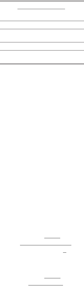
Torsion members (Fig. 50.7) are elements in the equivalent frame that provide moment transfer
between the horizontal slab beam and vertical columns. The cross section of torsional members are
assumed to consist of the portion of slab and beam having a width according to the conditions depicted
in Fig. 50.9. The stiffness K
t
of the torsional member is calculated by the following expression:
(50.112)
where E
cs
is the modulus of elasticity of the slab concrete and the torsional constant C may be evaluated
by dividing the cross section into separate rectangular parts and carrying out the following summation:
TABLE 50.10 Proportion of Moment to Column Strip in Percent
Interior Negative-Factored Moment
l
2
/l
1
0.5 1.0 2.0
(a
1
l
2
/l
1
) = 0 75 75 75
(a
1
l
2
/l
1
) ≥ 1.0 90 75 45
Positive-Factored Moment
(a
1
l
2
/l
1
) = 0 B
t
= 0 100 100 100
B
t
≥ 2.5 75 75 75
(a
1
l
2
/l
1
) ≥ 1.0 B
t
= 0 100 100 100
B
t
≥ 2.5 90 75 45
Exterior Negative-Factored Moment
(a
1
l
2
/l
1
) = 0 60 60 60
(a
1
l
2
/l
1
) ≥ 1.0 90 75 45
Source: ACI Committee 318, 1992.
K
EC
l
c
l
t
cs
=
-
Ê
Ë
Á
ˆ
¯
˜
Â
9
1
2
2
2
3
© 2003 by CRC Press LLC
Structural Concrete Design 50-35
(50.113)
where x and y are the shorter and longer dimension, respectively, of each rectangular part. Where beams
frame into columns in the direction of the span, the increased torsional stiffness K
ta
is obtained by
multiplying the value K
t
obtained from Eq. (50.112) by the ratio of (a) moment inertia of slab with such
beam, to (b) moment of inertia of slab without such beam. Various ways have been suggested for
incorporating torsional members into a computer model of an equivalent fame. The model implied by
the ACI Code is one that has the slab beam connected to the torsional members, which are projected
out of the plane of the columns. Others have suggested that the torsional members be replaced by
rotational springs at column ends or, alternatively, at the slab-beam ends. Or, instead of rotational springs,
columns may be modeled with an equivalent value of the moment of inertia modified by the equivalent
column stiffness K
ec
given in the commentary of the code. Using Fig. 50.7, K
ec
is computed as
(50.114)
where K
ct
and K
cb
are the top and bottom flexural stiffnesses of the column.
FIGURE 50.7 Equivalent column (columns plus torsional members).
actual column above
actual column below
torsional member K
ta
torsional member K
ta
parallel beam
K
ct
K
ct
K
cb
c
1
c
2
K
cb
B
A
1
1
2
2
2
/2
2
/2
col.
c
L
col.
c
L
C
x
y
xy
=-
Ê
Ë
Á
ˆ
¯
˜
Â
1063
3
3
.
K
KK
KK
KK
ec
ct cb
ct cb
ta ta
=
+
+
+
+
1
© 2003 by CRC Press LLC