Wai-Fah Chen.The Civil Engineering Handbook
Подождите немного. Документ загружается.


50-46 The Civil Engineering Handbook, Second Edition
(50.119)
(50.120)
(50.121)
In the above equations, f
y
is the reinforcement yield strength; f is 0.9 for Eq. (50.119) and 0.85 for
Eqs. (50.120) and (50.121). In Eq. (50.119), the lever arm jd can be approximated for all practical purposes
in most cases as 0.85d. Te nsile force N
uc
in Eq. (50.120) should not be taken less than 0.2V
u
unless special
provisions are made to avoid tensile forces. Tensile force N
uc
should be regarded as a live load even when
tension results from creep, shrinkage, or temperature change. In Eq. (50.121), V
i
/f(= V
n
) should not be
taken greater than 0.2f ¢
c
b
w
d nor 800b
w
d in pounds in normal-weight concrete. For “all-lightweight” or
“sand-lightweight” concrete, shear strength V
n
should not be taken greater than (0.2 – 0.07a/d)f ¢
c
b
w
d nor
(800 – 280a/d)b
w
d in pounds. The coefficient of friction m in Eq. (50.121) should be 1.4l for concrete
placed monolithically, 1.0l for concrete placed against hardened concrete with surface intentionally
roughened, 0.6l for concrete placed against hardened concrete not intentionally roughened, and 0.7l
for concrete anchored to as-rolled structural steel by headed studs or by reinforcing bars, where l is 1.0
for normal weight concrete, 0.85 for “sand-lightweight” concrete, and 0.75 for “all-lightweight” concrete.
Linear interpolation of l is permitted when partial sand replacement is used.
The total area of closed stirrups or ties A
h
parallel to A
s
should not be less than 0.5(A
s
– A
n
) and should
be uniformly distributed within two-thirds of the depth of the bracket adjacent to A
s
.
At front face of bracket or corbel, primary tension thermal A
s
should be anchored in one of the
following ways: (a) by a structural weld to a transverse bar of at least equal size; weld to be designed to
develop specified yield strength f
y
of A
s
bars; (b) by bending primary tension bars A
s
back to form a
horizontal loop, or (c) by some other means of positive anchorage. Also, to ensure development of the
yield strength of the reinforcement A
s
near the load, bearing area of load on bracket or corbel should
not project beyond straight portion of primary tension bars A
s
, nor project beyond interior face of
transverse anchor bar (if one is provided). When corbels are designed to resist horizontal forces, the
bearing plate should be welded to the tension reinforcement A
s
.
50.10 Footings
Footings are structural members used to support columns and walls and to transmit and distribute their
loads to the soil in such a way that (a) the load bearing capacity of the soil is not exceeded, (b) excessive
settlement, differential settlement, and rotations are prevented, and (c) adequate safety against overturn-
ing or sliding is maintained. When a column load is transmitted to the soil by the footing, the soil
becomes compressed. The amount of settlement depends on many factors, such as the type of soil, the
load intensity, the depth below ground level, and the type of footing. If different footings of the same
structure have different settlements, new stresses develop in the structure. Excessive differential settlement
may lead to the damage of nonstructural members in the buildings, even failure of the affected parts.
Ve rtical loads are usually applied at the centroid of the footing. If the resultant of the applied loads
does not coincide with the centroid of the bearing area, a bending moment develops. In this case, the
pressure on one side of the footing will be greater than the pressure on the other side causing higher
settlement on one side and a possible rotation of the footing.
If the bearing soil capacity is different under different footings — for example, if the footings of a
building are partly on soil and partly on rock — a differential settlement will occur. It is customary in
such cases to provide a joint between the two parts to separate them, allowing for independent settlement.
A
M
fjd
Va N h d
fjd
f
u
y
uuc
y
==
+-
()
ff
A
N
f
n
uc
y
=
f
A
V
f
vf
u
y
=
fm
© 2003 by CRC Press LLC
Structural Concrete Design 50-47
Types of Footings
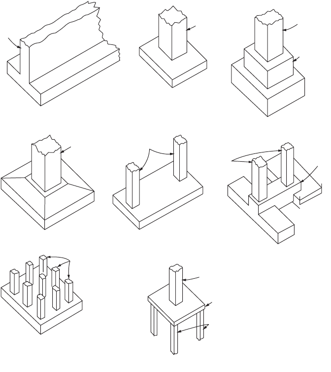
Different types of footings may be used to support building columns or walls. The most commonly used
ones are illustrated in Fig. 50.16(a–g). A simple file footing is shown in Fig. 50.16(h).
For walls, a spread footing is a slab wider than the wall and extending the length of the wall
[Fig. 50.16(a)]. Square or rectangular slabs are used under single columns [Fig. 50.16(b–d)]. When two
columns are so close that their footings would merge or nearly touch, a combined footing [Fig. 50.16(e)]
extending under the two should be constructed. When a column footing cannot project in one direction,
perhaps because of the proximity of a property line, the footing may be helped out by an adjacent footing
with more space; either a combined footing or a strap (cantilever) footing [Fig. 50.169f)] may be used
under the two.
For structures with heavy loads relative to soil capacity, a mat or raft foundation [Fig. 50.16(g)] may
prove economical. A simple form is a thick, two-way-reinforced-concrete slab extending under the entire
structure. In effect, it enables the structure to float on the soil, and because of its rigidity it permits
negligible differential settlement. Even greater rigidity can be obtained by building the raft foundation
as an inverted beam-and-girder floor, with the girders supporting the columns. Sometimes, also, inverted
flat slabs are used as mat foundations.
FIGURE 50.16 Common types of footings for walls and columns. (Source: ACI Committee 340, 1990.)
Wall
Column
Column
Pedestal
or Step
(a) Wall Footing (b) Simple Spread Footing
(c) Stepped or Pedestal
Footing
Column
Columns
Column
Column
Column
Strap
(d) Sloped Footing (e) Combined Footing
(f) Strap Footing
Pile Cap
Piles
(g) Mat, or Raft, Foundation
(h) Pile Foundation
© 2003 by CRC Press LLC

50-48 The Civil Engineering Handbook, Second Edition
Design Considerations
Footings must be designed to carry the column loads and transmit them to the soil safely while satisfying
code limitations. The design procedure must take the following strength requirements into consideration:
•The area of the footing based on the allowable bearing soil capacity
•Two-way shear or punching shear
• One-way shear
•Bending moment and steel reinforcement required
•Dowel requirements
•Development length of bars
•Differential settlement
These strength requirements will be explained in the following sections.
Size of Footings
The required area of concentrically loaded footings is determined from
(50.122)
where q
a
is allowable bearing pressure and D and L are, respectively, unfactored dead and live loads.
Allowable bearing pressures are established from principles of soil mechanics on the basis of load tests
and other experimental determinations. Allowable bearing pressures q
a
under service loads are usually
based on a safety factor of 2.5 and 3.0 against exceeding the ultimate bearing capacity of the particular
soil and to keep settlements within tolerable limits. The required area of footings under the effects of
wind W or earthquake E is determined from the following:
(50.123)
It should be noted that footing sizes are determined for unfactored service loads and soil pressures, in
contrast to the strength design of reinforced concrete members, which utilizes factored loads and factored
nominal strengths.
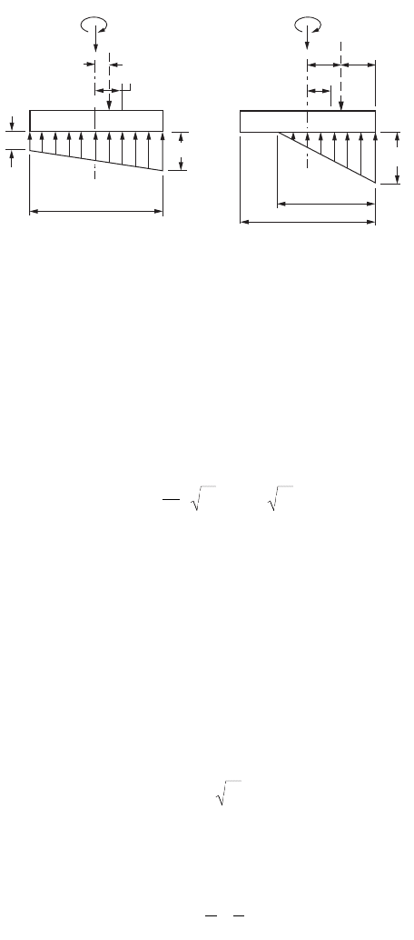
A footing is eccentrically loaded if the supported column is not concentric with the footing area or if
the column transmits — at its juncture with the footing — not only a vertical load but also a bending
moment. In either case, the load effects at the footing base can be represented by the vertical load P and
a bending moment M. The resulting bearing pressures are again assumed to be linearly distributed. As
long as the resulting eccentricity e = M/P does not exceed the kern distance k of the footing area, the
usual flexure formula
(50.124)
permits the determination of the bearing pressures at the two extreme edges, as shown in Fig. 50.17(a).
The footing area is found by trial and error from the condition q
max
£ q
a
. If the eccentricity falls outside
the kern, Eq. (50.124) gives a negative value for q along one edge of the footing. Because no tension can
be transmitted at the contact area between soil and footing, Eq. (50.124) is no longer valid and bearing
pressures are distributed as in Fig. 50.17(b).
Once the required footing area has been determined, the footing must then be designed to develop
the necessary strength to resist all moments, shears, and other internal actions caused by the applied
loads. For this purpose, the load factors of the ACI Code apply to footings as to all other structural
components.
A
DL
q
req
a
=
+
A
DLW
q
DLE
q
req
aa
=
++ ++
133 133..
or
q
P
A
Mc
I
max,min
=+
© 2003 by CRC Press LLC
Structural Concrete Design 50-49
Depth of footing above bottom reinforcement should not be less than 6 in. for footings on soil, nor
less that 12 in. from footings on piles.
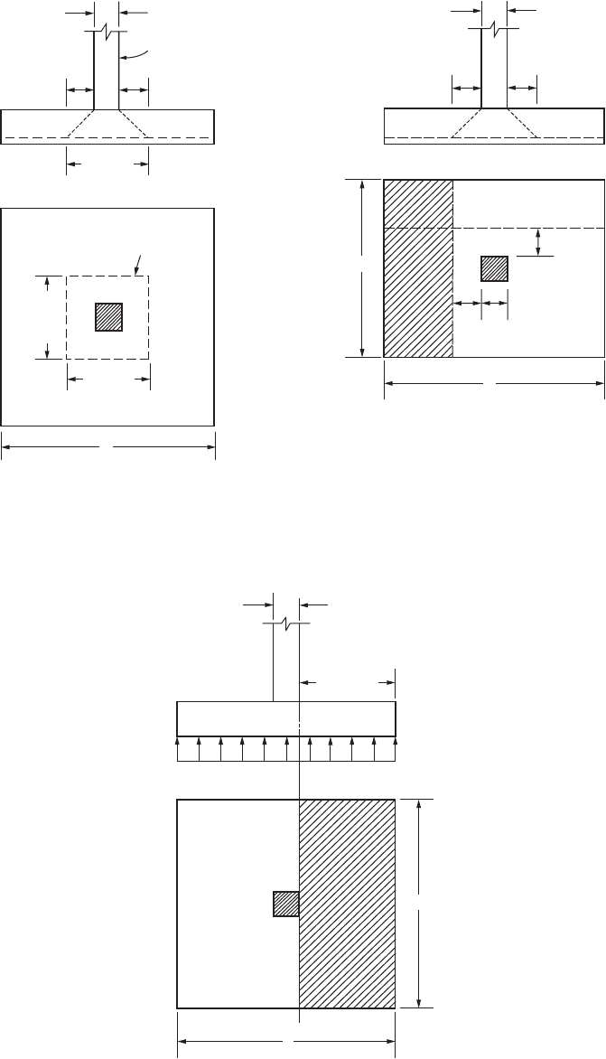
Two-Way Shear (Punching Shear)
ACI Code Sec. 11.12.2 allows a shear strength V
c
of footings without shear reinforcement for two-way
shear action as follows:
(50.125)
where b
c
is the ratio of long side to short side of rectangular area, b
o
is the perimeter of the critical section
taken at d/2 from the loaded area (column section), and d is the effective depth of footing. This shear is
a measure of the diagonal tension caused by the effect of the column load on the footing. Inclined cracks
may occur in the footing at a distance d/2 from the face of the column on all sides. The footing will fail
as the column tries to punch out part of the footing, as shown in Fig. 50.18.
One-Way Shear
For footings with bending action in one direction, the critical section is located at a distance d from the
face of the column. The diagonal tension at section m-m in Fig. 50.19 can be checked as is done in beams.
The allowable shear in this case is equal to
(50.126)
where b is the width of section m-m. The ultimate shearing force at section m-m can be calculated as
follows:
(50.127)
where b is the side of footing parallel to section m-m.
Flexural Reinforcement and Footing Reinforcement
The theoretical sections for moment occur at face of the column (section n-n, Fig. 50.20). The bending
moment in each direction of the footing must be checked and the appropriate reinforcement must be
provided. In square footings the bending moments in both directions are equal. To determine the
reinforcement required, the depth of the footing in each direction may be used. As the bars in one
FIGURE 50.17 Assumed bearing pressures under eccentric footings. (Source: Wang and Salmon, 1985.)
MM
P
P
me
k
P
P
e
k
l
l
(a) (b)
q
max
q
max
q
min
3
m
c
L
c
L
Vfbdfbd
c
c
co co
=+
Ê
Ë
Á
ˆ
¯
˜
¢
£
¢
2
4
4
b
ffVfbd
cc
=
¢
2
Vqb
Lc
d
uu
=--
Ê
Ë
Á
ˆ
¯
˜
22
© 2003 by CRC Press LLC
50-50 The Civil Engineering Handbook, Second Edition
FIGURE 50.18 Punching shear (two-way).
(Source: MacGregor, 1992.)
FIGURE 50.19 One-way shear. (Source: MacGregor,
1992.)
FIGURE 50.20 Critical section of bending moment. (Source: MacGregor, 1992.)
c
Column
d
/2
d
/2
(
c
+
d
)
Critical
section
L
(
c
+
d
)
(
c
+
d
)
c
dd
d
d
c
b
L
(m)
(m)
c
n
b
(
L
−
c
)/2
q
u
n
L
© 2003 by CRC Press LLC
Structural Concrete Design 50-51
direction rest on top of the bars in the other direction, the effective depth d varies with the diameter of
the bars used. The value of d
min
may be adopted.
The depth of footing is often controlled by the shear, which requires a depth greater than that required
by the bending moment. The steel reinforcement in each direction can be calculated in the case of flexural
members as follows:
(50.128)
The minimum steel percentage requirement in flexural members is equal to 200/f
y
. However, ACI
Code Sec. 10.5.3 indicates that for structural slabs of uniform thickness, the minimum area and maximum
spacing of steel in the direction of bending should be as required for shrinkage and temperature rein-
forcement. This last minimum steel reinforcement is very small and a higher minimum reinforcement
ratio is recommended, but not greater than 200/f
y
.
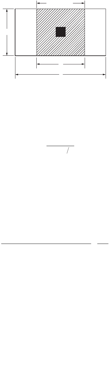
The reinforcement in one-way footings and two-way footings must be distributed across the entire
width of the footing. In the case of two-way rectangular footings, ACI Code Sec. 15.4.4 specifies that in
the long direction the total reinforcement must be placed uniformly within a band width equal to the
length of the short side of the footing according to
(50.129)
where b is the ratio of the long side to the short side of the footing. The band width must be centered
on the centerline of the column (Fig. 50.21). The remaining reinforcement in the short direction must
be uniformly distributed outside the band width. This remaining reinforcement percentage should not
be less than required for shrinkage and temperature.
When structural steel columns or masonry walls are used, the critical sections for moments in footings
are taken at halfway between the middle and the edge of masonry walls, and halfway between the face
of the column and the edge of the steel base place (ACI Code Sec. 15.4.2).
Bending Capacity of Column at Base
The loads from the column act on the footing at the base of the column, on an area equal to the area of
the column cross section. Compressive forces are transferred to the footing directly by bearing on the
concrete. Tensile forces must be resisted by reinforcement, neglecting any contribution by concrete.
Forces acting on the concrete at the base of the column must not exceed the bearing strength of
concrete as specified by the ACI Code Sec. 10.15:
(50.130)
FIGURE 50.21 Band width for reinforcement distribution. (Source: MacGregor, 1992.)
Band width
b
b
L
A
M
fd a
s
u
y
=
-
()
f 2
Reinforcement band width
Total reinforcement in short direction
=
+
2
1b
NfA
c
=
¢
()
f 085
1
.
© 2003 by CRC Press LLC
50-52 The Civil Engineering Handbook, Second Edition
where f is 0.7 and A
1
is the bearing area of the column. The value of the bearing strength given in
Eq. (50.130) may be multiplied by a factor £ 2.0 for bearing on footings when the supporting
surface is wider on all sides other than the loaded area. Here A
2
is the area of the part of the supporting
footing that is geometrically similar to and concentric with the loaded area (Fig. 50.22). Since A
2
> A
1
,
the factor is greater than unity, indicating that the allowable bearing strength is increased because
of the lateral support from the footing area surrounding the column base. If the calculated bearing force
is greater than N or the modified one with r , reinforcement must be provided to transfer the
excess force. This is achieved by providing dowels or extending the column bars into the footing. If the
calculated bearing force is less than either N or the modified one with r , then minimum
reinforcement must be provided. ACI Code Sec. 15.8.2 indicates that the minimum area of the dowel
reinforcement is at least 0.005A
g
but not less than 4 bars, where A
g
is the gross area of the column section
of the supported member. The minimum reinforcement requirements apply to the case in which the
calculated bearing forces are greater than N or the modified one with r .
Dowel on Footings
It was explained earlier that dowels are required in any case, even if the bearing strength is adequate. The
ACI Code specifies a minimum steel ratio r = 0.005 of the column section as compared to r = 0.01 as
minimum reinforcement for the column itself. The minimum number of dowel bars needed is four;
these may be placed at the four corners of the column. The dowel bars are usually extended into the
footing, bent at their ends, and tied to the main footing reinforcement.
ACI Code Sec. 15.8.2 indicates that #14 and #18 longitudinal bars, in compression only, may be lap-
spliced with dowels. Dowels should not be larger than #11 bar and should extend (1) into supported
member a distance not less than the development length of #14 or 18≤ bars or the splice length of the
dowels — whichever is greater, and (2) into the footing a distance not less than the development length
of the dowels.
Development Length of the Reinforcing Bars
The critical sections for checking the development length of the reinforcing bars are the same as those
for bending moments. Calculated tension or compression in reinforcement at each section should be
developed on each side of that section by embedment length, hook (tension only) or mechanical device,
or a combination thereof. The development length for a compression bar is
(50.131)
but not less than 0.0003f
y
d
b
≥ 8 in. For other values, refer to ACI Code, Chapter 12. Dowels bars must
also be checked for proper development length.
FIGURE 50.22 Bearing areas on footings. A
1
= c
2
, A
2
= b
2
. (Source: MacGregor, 1992.)
A
2
A
1
c
c
b
L
b
AA
21
AA
21
AA
21
AA
21
AA
21
lfdf
dybc
=
¢
002.
© 2003 by CRC Press LLC
Structural Concrete Design 50-53
Differential Settlement
Footings usually support the following loads:
•Dead loads from the substructure and superstructure
•Live loads resulting from materials or occupancy
•Weight of materials used in backfilling
•Wind loads
Each footing in a building is designed to support the maximum load that may occur on any column due
to the critical combination of loadings, using the allowable soil pressure.
The dead load, and maybe a small portion of the live load, may act continuously on the structure.
The rest of the live load may occur at intervals and on some parts of the structure only, causing different
loadings on columns. Consequently, the pressure on the soil under different loadings will vary according
to the loads on the different columns, and differential settlement will occur under the various footings
of one structure. Since partial settlement is inevitable, the problem is defined by the amount of differential
settlement that the structure can tolerate. The amount of differential settlement depends on the variation
in the compressibility of the soils, the thickness of the compressible material below foundation level, and
the stiffness of the combined footing and superstructure. Excessive differential settlement results in
cracking of concrete and damage to claddings, partitions, ceilings, and finishes.
For practical purposes it can be assumed that the soil pressure under the effect of sustained loadings
is the same for all footings, thus causing equal settlements. The sustained load (or the usual load) can
be assumed equal to the dead load plus a percentage of the live load, which occurs very frequently on
the structure. Footings then are proportioned for these sustained loads to produce the same soil pressure
under all footings. In no case is the allowable soil bearing capacity to be exceeded under the dead load
plus the maximum live load for each footing.
Wall Footings
The spread footing under a wall [Fig. 50.16(a)] distributes the wall load horizontally to preclude excessive
settlement. The wall should be so located on the footings as to produce uniform bearing pressure on the
soil (Fig. 50.23), ignoring the variation due to bending of the footing. The pressure is determined by
dividing the load per foot by the footing width.
The footing acts as a cantilever on opposite sides of the wall under downward wall loads and upward
soil pressure. For footings supporting concrete walls, the critical section for bending moment is at the
face of the wall; for footings under masonry walls, halfway between the middle and edge of the wall.
FIGURE 50.23 Reinforced-concrete wall footing. (Source: Wang and Salmon, 1985.)
d
d
L
t
a
q
WALL
© 2003 by CRC Press LLC

50-54 The Civil Engineering Handbook, Second Edition
Hence, for a one-foot-long strip of symmetrical concrete-wall footing, symmetrically loaded, the maxi-
mum moment, ft-lb, is
(50.132)
where q
u
= the uniform pressure on soil (lb/ft
2
)
L = the width of footing (ft)
a = wall thickness (ft)
For determining shear stresses, the vertical shear force is computed on the section located at a distance d
from the face of the wall. Thus,
(50.133)
The calculation of development length is based on the section of maximum moment.
Single-Column Spread Footings
The spread footing under a column [Fig. 50.16(b–d)] distributes the column load horizontally to prevent
excessive total and differential settlement. The column should be located on the footing so as to produce
uniform bearing pressure on the soil, ignoring the variation due to bending of the footing. The pressure
equals the load divided by the footing area.
In plan, single-column footings are usually square. Rectangular footings are used if space restrictions
dictate this choice or if the supported columns are of strongly elongated rectangular cross section. In the
simplest form, they consist of a single slab [Fig. 50.16(b)]. Another type is that of Fig. 50.16(c), where
a pedestal or cap is interposed between the column and the footing slab; the pedestal provides for a more
favorable transfer of load and in many cases is required in order to provide the necessary development
length for dowels. This form is also known as a stepped footing. All parts of a stepped footing must be
poured in a single pour in order to provide monolithic action. Sometimes sloped footings like those in
Fig. 50.16(d) are used. They require less concrete than stepped footings, but the additional labor necessary
to produce the sloping surfaces (formwork, etc.) usually makes stepped footings more economical. In
general, single-slab footings [Fig. 16(b)] are most economical for thicknesses up to 3 ft.
The required bearing area is obtained by dividing the total load, including the weight of the footing,
by the selected bearing pressure. Weights of footings, at this stage, must be estimated and usually amount
to 4 to 8% of the column load, the former value applying to the stronger types of soils.
Once the required footing area has been established, the thickness h of the footing must be determined.
In single footings the effective depth d is mostly governed by shear. Two different types of shear strength
are distinguished in single footings: two-way (or punching) shear and one-way (or beam) shear. Based
on the Eqs. (50.125) and (50.126) for punching and one-way shear strength, the required effective depth
of footing d is calculated.
Single-column footings represent, as it were, cantilevers projecting out from the column in both
directions and loaded upward by the soil pressure. Corresponding tension stresses are caused in both
these directions at the bottom surface. Such footings are therefore reinforced by two-layers of steel,
perpendicular to each other and parallel to the edge. The steel reinforcement in each direction can be
calculated using Eq. (50.128). The critical sections for development length of footing bars are the same
as those for bending. Development length may also have to be checked at all vertical planes in which
changes of section or of reinforcement occur, as at the edges of pedestals or where part of the reinforce-
ment may be terminated.
When a column rests on a footing or pedestal, it transfers its load to only a part of the total area of
the supporting member. The adjacent footing concrete provides lateral support to the directly loaded
MqLa
uu
=-
()
1
8
2
Vq
La
L
uu
=
-
-
Ê
Ë
Á
ˆ
¯
˜
2
© 2003 by CRC Press LLC
Structural Concrete Design 50-55
part of the concrete. This causes triaxial compression stresses that increase the strength of the concrete,
which is loaded directly under the column. The design bearing strength of concrete must not exceed the
one given in Eq. (50.130) for forces acting on the concrete at the base of column and the modified one
with r for supporting area wider than the loaded area. If the calculated bearing force is greater
than the design bearing strength, reinforcement must be provided to transfer the excess force. This is
done either by extending the column bars into the footing or by providing dowels, which are embedded
in the footing and project above it.
Combined Footings
Spread footings that support more than one column or wall are known as combined footings. They can
be divided into two categories: those that support two columns, and those that support more than two
(generally large numbers of) columns.
In buildings where the allowable soil pressure is large enough for single footings to be adequate for
most columns, two-column footings are seen to become necessary in two situations: (1) if columns are
so close to the property line that single-column footings cannot be made without projecting beyond that
line, and (2) if some adjacent columns are so close to each other that their footings would merge.
When the bearing capacity of the subsoil is low so that large bearing areas become necessary, individual
footings are replaced by continuous strip footings, which support more than two columns and usually
all columns in a row. Mostly, such strips are arranged in both directions, in which case a grid foundation
is obtained, as shown in Fig. 50.24. Such a grid foundation can be done by single footings because the
individual strips of the grid foundation represent continuous beams whose moments are much smaller
than the cantilever moments in large single footings that project far out from the column in all four
directions.
For still lower bearing capacities, the strips are made to merge, resulting in a mat foundation, as shown
in Fig. 50.25. That is, the foundation consists of a solid reinforced concrete slab under the entire building.
In structural action such a mat is very similar to a flat slab or a flat plate, upside down — that is, loaded
upward by the bearing pressure and downward by the concentrated column reactions. The mat founda-
tion evidently develops the maximum available bearing area under the building. If the soil’s capacity is
so low that even this large bearing area is insufficient, some form of deep foundation, such as piles or
caissons, must be used.
Grid and mat foundations may be designed with the column pedestals — as shown in Figs. 50.24 and
50.25 — or without them, depending on whether or not they are necessary for shear strength and the
development length of dowels. Apart from developing large bearing areas, another advantage of grid and
mat foundations is that their continuity and rigidity help in reducing differential settlements of individual
columns relative to each other, which may otherwise be caused by local variations in the quality of subsoil,
FIGURE 50.24 Grid foundation. (Source: Wang and Salmon, 1985).
AA
21
a a
© 2003 by CRC Press LLC