Watts J.F., Wolstenholme J. An Introduction to Surface Analysis by XPS and AES
Подождите немного. Документ загружается.

SMALL
AREA
XPS 47
charge using
a
pulse amplifier
and
produce
a
square wave which
can be
counted
by a
rate meter.
Use of a
discriminator eliminates noise signals
emanating
from
the
channeltron
or the
preamplifier.
The
channeltron samples
about
5 mm in the
dispersive direction
of the
analyser
and
about
15mm
in the
non-dispersive direction.
In
order
to
increase
the
sensitivity
of the
spectrometer
it is
common
to use an
array
of
channeltrons
as the
detector.
The
channeltrons
are
arranged along
the
dispersive
direction
and so
each
one
collects
a
different
electron kinetic
energy.
The
data system sums
the
output
from
each channeltron
after
applying
the
appropriate energy
shift.
Channeltrons
can be
capable
of
detecting
up to
about
3 x
10
6
counts/s
although they become non-linear
at
very
high count rates.
2.6.2
Channel plates
A
channel plate
is a
disc having
an
array
of
small holes. Each
of
these
holes behaves
as a
small channeltron.
The
gain
of an
individual channel
is
much lower than
that
of a
channeltron
so it is
common
to use a
pair
of
channel plates
in
tandem.
The
maximum count rate which
can be de-
tected using channel plates
is
about
3x10
counts/s
on
current systems
for
two-dimensional detection,
but in
principle could
be as
high
as
1 x 10
7
counts/s
for
simple spectroscopy.
Channel
plates
are
used when
it is
necessary
to
detect data
in two
dimensions;
spectrometers
have been designed using channel plates
to
measure
signals:
• in an X-Y
array
for
parallel acquisition
of
photoelectron images,
• in an
X-energy array
for
parallel acquisition
of XPS
line scans,
• in an
energy-angle array
for the
parallel
acquisition
of
angle resolved
XPS
spectra.
2.7
Small Area
XPS
It
is
often
desirable
to
analyse
a
small
feature
or
imperfection
on the
surface
of a
sample.
For the
analysis
to be
effective,
as
much
as
possible
48
ELECTRON
SPECTROMETER
DESIGN
of
the
signal from
the
surrounding area should
be
excluded. This
is
usually
done
in one of two
ways.
1. By
flooding
the
analysis area with X-rays
but
limiting
the
area
from
which
the
photoelectrons
are
collected using
the
transfer lens. This
is
described
as
lens-defined
small
area analysis.
2. By
focusing
a
monochromated beam
of
X-rays into
a
small
spot
on
the
sample, described
as
source-defined small area analysis.
2.7.1 Lens-defined small area
XPS
In
most
spectrometers
the
transfer lens
fitted to the
analyser
is
operated
in
such
a way as to
produce
a
photoelectron image
at
some point
in the
electron optical column.
If a
small aperture
is
placed
at
this point then
only electrons emitted
from
a
defined area
of the
sample
can
pass
through
the
aperture
and
reach
the
analyser.
If the
magnification
of
the
lens
is M and the
diameter
of the
aperture
is d
then
the
diameter
of
the
analysed area
is
d/M.
In
some instruments,
an
aperture
can be
selected
from
a
number
of fixed
apertures while
in
other instruments
an
iris
is
used
to
provide
a
continuous range
of
analysis areas.
Spherical
aberrations, which occur
in any
electron optical lens system,
mean that
the
acceptance angle
of the
lens
has to be
limited
to
provide
good
edge resolution
in the
analysis
area. This
is
achieved using either
another
set of fixed
apertures
or
another
iris
placed
at
some point
re-
mote
from
the
image
position
of the
lens. Using this technique,
com-
mercial
instruments
can
provide small area
analysis
down
to
about
15 um.
This
is an
effective
method
for
producing high-quality,
small
area
XPS
data
but it
suffers
from
a
disadvantage. Reducing
the
angular accep-
tance
of the
lens reduces
the
detected
flux
per
unit area
of the
sample.
This means that analysis times
can
become very long. During
the
anal-
ysis
time
the
whole
of the
sample
(or
samples
in a
multi-sample
ex-
periment)
is
being exposed
to
X-rays, potentially resulting
in
radiation
damage. Therefore,
if
many samples
or
many points
on a
single
sample
are to be
analysed then
the
analyst cannot
be
certain that
the
surface
remains
unaltered.
XPS
IMAGING
AND
MAPPING
49
2.7.2
Source-defined
smalt
area
analysis
It
is
possible
to
shape
a
quartz crystal
so
that
it can
focus
a
beam
of
electrons
and
provide monochromatic X-rays
by
diffraction.
In
this
re-
spect,
it
behaves rather like
a
concave mirror.
The
focusing
is
usually
achieved
using
a
magnification
of
unity which means
that
the
size
of
the
X-ray spot
on the
sample
is
approximately equal
to the
size
of
the
electron spot
on the
X-ray anode. Analysis areas down
to
about
10 um can be
achieved
in
commercial instruments using this
method.
Because
the
source
of
X-rays
is
defining
the
analysis area, aberrations
in
the
transfer lens will
not
affect
the
analysis area
and so the
lens
can be
operated
at its
maximum transmission, regardless
of how
small
the
analysis
area becomes.
The
sensitivity
of a
spectrometer operating
in
this
mode
is
therefore much higher than that
of an
equivalent instrument
operating
in the
lens defined mode.
This
reduces
the
danger
of
sample
damage during analysis
and
eliminates radiation damage
to the
sur-
rounding area
of the
sample(s).
The
intensity
of the
X-ray beam
is
proportional
to the
intensity
of
the
electron beam
at the
anode.
The
intensity
of the
electron beam
at the
anode
is
limited
by the
rate
at
which heat
can be
removed
from
the
vicinity
of the
electron
spot.
The
X-ray source
can be
operated
at
several
hundred
watts
for
large area analysis while
it is
only possible
to use a
few
watts
at the
smallest areas.
2.8
XPS imaging and
Mapping
A
logical extension
to
small area
XPS is to
produce
an
image
or map of
the
surface. Such
an
image
or map
shows
the
distribution
of an
element
or a
chemical state
on the
surface
of the
sample. There
are two
distinct
approaches, used
by
manufacturers,
to
obtaining
XPS
maps.
1.
Serial acquisition
in
which each pixel
of the
image
is
collected
in
turn.
2.
Parallel acquisition
in
which data from
the
whole
of the
analysis area
is
collected simultaneously.
50
ELECTRON
SPECTROMETER
DESIGN
2.8.1
Serial
acquisition
Serial
acquisition
of
images
is
based
on a
two-dimensional, rectangular
array
of
small area
XPS
analyses.
By
this means,
the
distribution
of
elements
or
chemical
states
can be
measured.
The
ultimate spatial
re-
solution
in the
image
is
determined
by the
size
of the
smallest analysis
area (this depends upon
the
instrument
but 10 um is
possible using
a
high-quality, modern source-defined spectrometer). Serial acquisition
is
generally
slower than parallel acquisition
but has the
advantage that
one
can
collect
a
range
of
energies
at
each pixel whereas,
in
parallel
acquisi-
tion,
only
a
single energy
can be
collected during each acquisition.
There
are
several methods
by
which
the
analysis area
can be
stepped
over
the field of
view
of the
image.
1.
Scanning
the
sample stage. Using this method,
the
analysis position
is
fixed in
space
and the
sample surface
is
moved with
respect
to
this position.
The
advantages
of
this method
are
that
all of the
important
instrumental
conditions
remain
constant
(e.g.,
the
energy
of
the
X-ray beam,
the
resolution
of the
analysis
spot,
and the
transmission function
of the
lens)
and the
maximum size
of the
image
field
of
view
is
limited only
by the
range
of
motion
of the
sample
stage.
The
disadvantages
of the
method
are
that
it
tends
to be
slower
than other methods
and
requires
a
high-precision stage with
low
backlash.
2.
Scanning
the
lens. This method requires that
two
pairs
of
deflector
plates
be
built
into
the
transfer lens.
By
applying potentials
to
these
plates,
the
photoelectron image
can be
deflected with respect
to the
area-defining
aperture
within
the
transfer lens.
The
analysis area
can
therefore
be
scanned
in the X and Y
directions
and a map
built
up.
The
advantage
of
this
method
is
that
it is
faster than scanning
the
sample stage
but it
suffers
from
a
major
disadvantage.
The
resolution
of
the map
rapidly degrades
as a
function
of
distance
from
the
centre
of
the map due to the
spherical aberrations which
are
inevitably
present
in the
electrostatic lens.
3.
Scanning
the
monochromated
X-ray spot.
As
mentioned
in the
discussion
of
small area XPS,
it is
possible
to
produce
an
X-ray image
XPS
IMAGING
AND
MAPPING
5 ]
of
the
spot
of
electrons
on the
X-ray anode. Therefore,
if the
spot
of
electrons
is
scanned
on the
anode,
the
X-ray beam will
be
scanned
on
the
sample surface. Again,
the
transfer lens
can be
operated
in its
maximum
transmission mode because
it
does
not
contribute
to
the
spatial resolution.
The
advantages
of
this method
are the
same
as
those
for
source-defined small area
XPS.
The
disadvantage
is
that
the field of
view
is
very limited. This
is
especially true
in the
direction
of the
Bragg angle.
As the
electron beam
is
scanned over
the
anode,
the
diffraction angle
is
changing
and so the
wavelength
of
the
X-rays reaching
the
sample
is
changing.
In
turn, this means
that
the
kinetic energy
of the
photoelectrons will change
and so the
energy
to
which
the
analyser
is
tuned must
be
adjusted
as a
function
of
distance.
If the
deflection angle
is too
large there
will
be no
intensity
in the
AlKa radiation
at the
required wavelength
and so
photoemission
is not
possible.
If it is
necessary
to map
large areas
of
the
sample, this method must
be
used
in
combination with stage
scanning.
2.8.2
Parallel acquisition
In
parallel acquisition
of
photoelectron images,
the
whole
of the field of
view
is
imaged simultaneously without scanning voltages being applied
to any
component
of the
spectrometer.
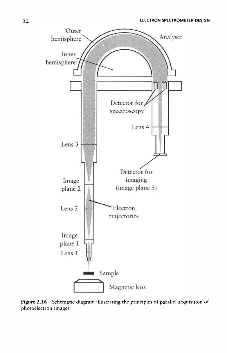
To
obtain images
via
this route, additional lenses
are
required
in the
spectrometer. These must also
be
equipped with
a
two-dimensional
detector. Figure
2.16
shows schematically
how the
method works.
The
photoelectrons pass through lenses
1 and 2 in the
transfer lens
assembly,
producing
a
photoelectron image
of the
specimen surface
at
some plane within
the
lens column
after
each lens
(the
image planes).
Lens
3 is
operated such that
its
focal
length
is
equal
to the
distance
between
the
lens
and the
second image plane. This means
that
electrons
emanating
from
any one
point
on the
image will leave lens
3 on
parallel
paths.
The
angle between
the
beam
of
electrons
and the
lens axis will
depend only upon their distance from
the
lens axis
in the
image plane.
The
electrons then enter
the
analyser, which functions
as
both
an
energy
filter and a
lens.
If the
deflection angle
of the
analyser
is
180°
then
the
angular distribution
of the
electrons
as
they leave
the
analyser
is
52
ELECTRON
SPECTROMETER
DESIGN
Figure 2.16 Schematic diagram illustrating
the
principles
of
parallel acquisition
of
photoelectron
images
XPS
IMAGING
AND
MAPPING
53
retained. Therefore
a
fourth lens
(lens
4)
operated
in the
reverse manner
to
that
of
lens
3
will reconstruct
the
image
at a
two-dimensional detec-
tor
placed
at the
focal
length
of
lens
4.
The
spatial resolution
of
parallel imaging
is
dependent upon
the
spher-
ical
aberrations
in the
lens. Limiting
the
angular acceptance
of the
lens
can
reduce
the
effect
of the
aberrations
and so
resolution
can be im-
proved
at the
expense
of
sensitivity.
The use of a
magnetic immersion
lens
in the
sample region
also
reduces aberrations
and
therefore allows
higher
sensitivity
at a
given resolution.
This
method
of
imaging
is
rela-
tively
fast
and
commercial instruments
can
produce images with
an
image
resolution
of
<3um.
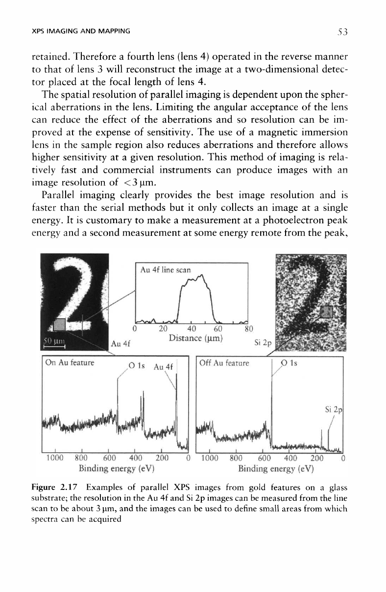
Parallel
imaging clearly provides
the
best image resolution
and is
faster
than
the
serial methods
but it
only collects
an
image
at a
single
energy.
It is
customary
to
make
a
measurement
at a
photoelectron peak
energy
and a
second measurement
at
some energy remote
from
the
peak,
Figure
2.17 Examples
of
parallel
XPS
images from gold features
on a
glass
substrate;
the
resolution
in the Au 4f and Si 2p
images
can be
measured
from
the
line
scan
to be
about
3 um, and the
images
can be
used
to
define small
areas
from
which
spectra
can be
acquired
54
ELECTRON
SPECTROMETER
DESIGN
where
the
signal intensity
is
approximately equal
to the
estimated back-
ground signal under
the
peak maximum.
By
subtracting
the
background
signal from
the
signal
at the
peak maximum,
a
more accurate measure-
ment
can be
made. This
is in
contrast with
the use of a
serial mapping
method
in
conjunction with
a
multi-channel
detector,
to
produce
a
'snapshot'
spectrum
at
each pixel
of the
map. Such spectra
can
then
be
treated with advanced data processing techniques
in
order
to
extract
the
maximum chemical information
from
the
image.
Figure 2.17 shows examples
of XPS
images
from
parallel acquisi-
tion
using
monochromated
AlKa X-rays. This sample
was a
glass
substrate with gold features. Images
from
Au 4f and Si 2p are
shown
along with
an
intensity line scan measured
from
the Au 4f
image.
The
line scan
indicates
that
the
lateral resolution
in
this image
is
about
3 um.
These images
can be
used
to
define
areas
for
spectros-
copy.
A 25 um
square area
was
selected
from
the
gold region
of the
sample
and
from
the
glass
- the
respective spectra
are
also shown
in
Figure
2.17. Images such
as
these
can be
acquired
in
just
a few
minutes,
those
in
Figure 2.17 were
collected
in
4min (2min
for the
peak image
and 2 min for the
background)
and the
spectra were
collected
in
less than
2 min
each.
The
sample
was an
insulator
and so
required
the use of an
electron
flood gun to
control
the
sample charging.
2.9
Lateral
Resolution
in
Smail
Area
XPS
To
estimate
the
lateral resolution
in
small area XPS,
the
following prac-
tice
is
adopted.
Assume, initially, that
the
analysis area
in a
small area
mode
of
acquisition
is
circular and, outside this area, there
is no
trans-
mission. Transmission
is
uniform within
the
area (i.e.,
the
transmission
as
a
function
of
position
on the
sample resembles
a
'top hat' distribu-
tion).
To
determine
the
dimensions
of the
analysis area
a
knife-edge
sample (often silver)
is
translated through
the
analysis area while mea-
suring
the XPS
signal
from
the
knife-edge (e.g.,
the
signal
from
the Ag
3d
5/3
peak),
see
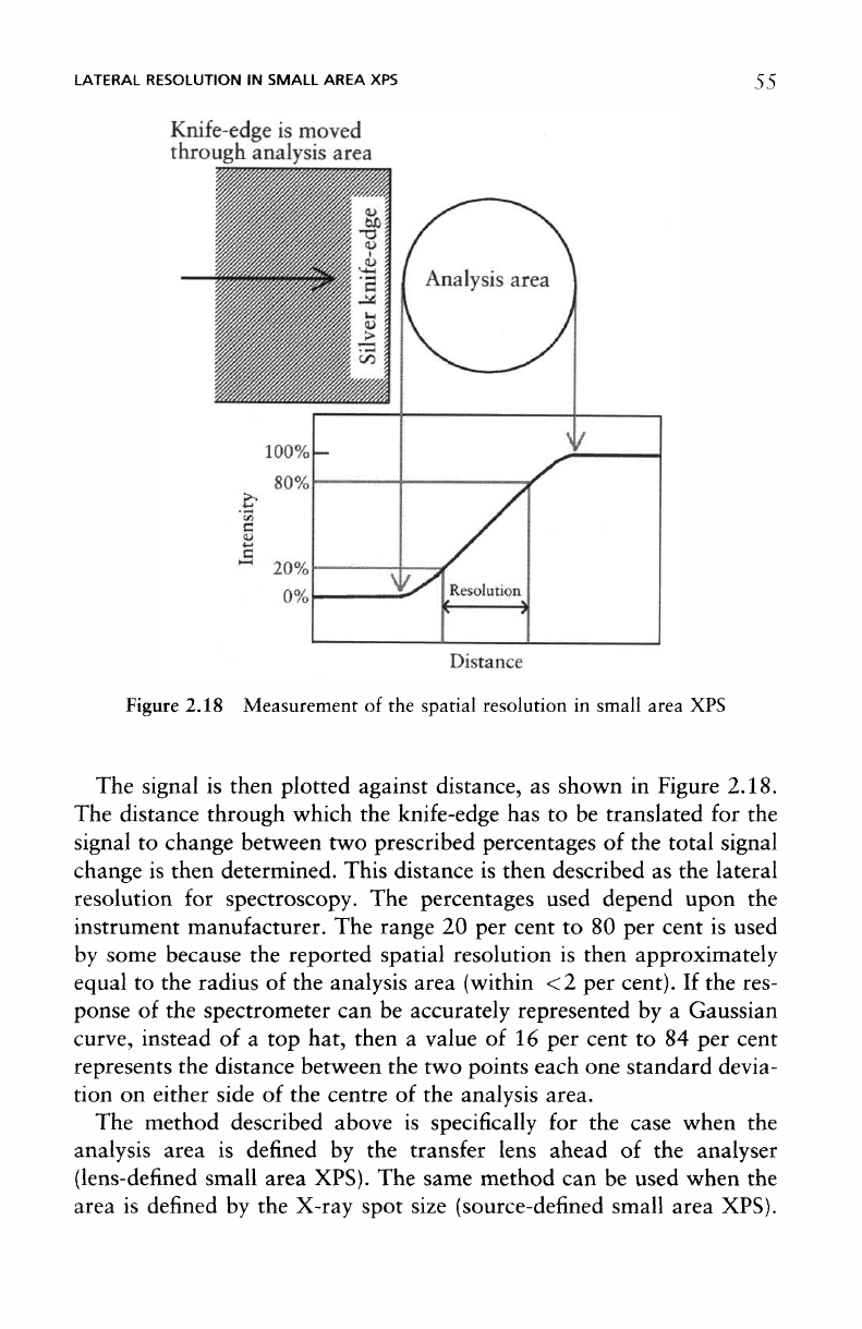
Figure 2.18.
The
signal
is
initially zero until
the
knife-
edge begins
to
intercept
the
analysis area when
it
begins
to
rise.
The
intensity
of the
signal continues
to
rise
until
the
silver
completely
fills the
whole
of the
analysis area.
LATERAL
RESOLUTION
IN
SMALL AREA
XPS 55
Figure
2.18 Measurement
of the
spatial resolution
in
small area
XPS
The
signal
is
then plotted against distance,
as
shown
in
Figure 2.18.
The
distance through which
the
knife-edge
has to be
translated
for the
signal
to
change between
two
prescribed percentages
of the
total signal
change
is
then determined. This distance
is
then described
as the
lateral
resolution
for
spectroscopy.
The
percentages used depend upon
the
instrument manufacturer.
The
range
20 per
cent
to 80 per
cent
is
used
by
some because
the
reported spatial resolution
is
then approximately
equal
to the
radius
of the
analysis area (within
<2 per
cent).
If the
res-
ponse
of the
spectrometer
can be
accurately represented
by a
Gaussian
curve,
instead
of a top
hat, then
a
value
of 16 per
cent
to 84 per
cent
represents
the
distance between
the two
points each
one
standard devia-
tion
on
either side
of the
centre
of the
analysis area.
The
method described above
is
specifically
for the
case when
the
analysis area
is
defined
by the
transfer lens ahead
of the
analyser
(lens-defined
small area XPS).
The
same method
can be
used when
the
area
is
defined
by the
X-ray spot size (source-defined small area XPS).
56
ELECTRON
SPECTROMETER
DESIGN
Measurement
of
lateral resolution should
be
made
in two
orthogonal
directions
in
case
the
analysis area
is not
circular.
2.10
Angle
Resolved
XPS
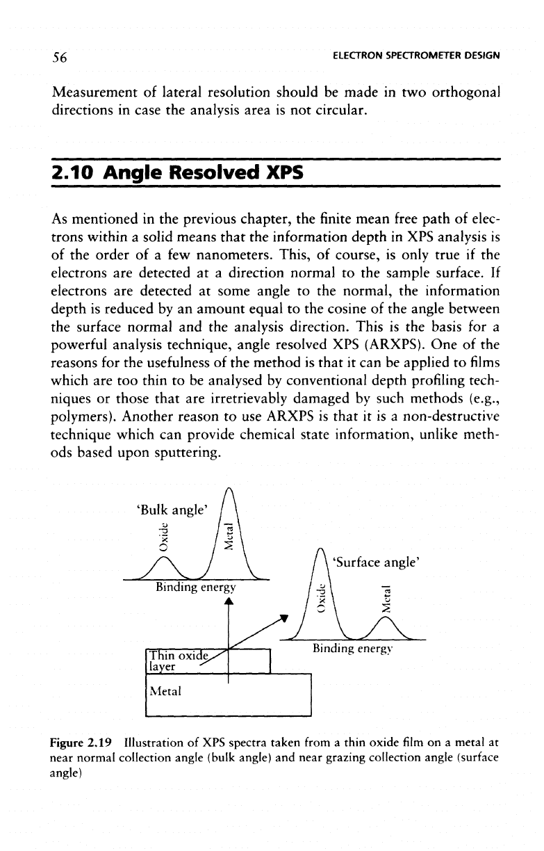
As
mentioned
in the
previous chapter,
the finite
mean
free
path
of
elec-
trons
within
a
solid means
that
the
information depth
in XPS
analysis
is
of
the
order
of a few
nanometers.
This,
of
course,
is
only true
if the
electrons
are
detected
at a
direction normal
to the
sample surface.
If
electrons
are
detected
at
some angle
to the
normal,
the
information
depth
is
reduced
by an
amount equal
to the
cosine
of the
angle between
the
surface normal
and the
analysis direction. This
is the
basis
for a
powerful
analysis technique, angle resolved
XPS
(ARXPS).
One of the
reasons
for the
usefulness
of the
method
is
that
it can be
applied
to films
which
are too
thin
to be
analysed
by
conventional depth profiling tech-
niques
or
those that
are
irretrievably damaged
by
such methods (e.g.,
polymers). Another reason
to use
ARXPS
is
that
it is a
non-destructive
technique
which
can
provide chemical state
information,
unlike
meth-
ods
based upon sputtering.
'Bulk
angle
'Surface
angle'
Figure
2.19 Illustration
of XPS
spectra taken
from
a
thin oxide
film on a
metal
at
near
normal collection angle
(bulk
angle)
and
near
grazing
collection
angle
(surface
angle)