Yam, Kit L. (ed.). The Wiley encyclopedia of packaging technology
Подождите немного. Документ загружается.

solids radiation curable silicone release coatings, which
are used for pressure-sensitive adhesive labels and other
products. The transfer roll coater is a direct roll coater.
The rubber-covered applicator roll is run 5–25 times faster
than the transfer roll, and this decreases the amount of
coating transferred to the substrate by that factor.
Reverse Roll Coaters. The main feature of the reverse
roll coater is that the applicator roll rotates in the direc-
tion opposite to the web travel (therefore, reverse roll) and
transfers the coating by wiping. These coaters are versa-
tile machines. Among the advantages of reverse roll coat-
ing are (a) the possibility to handle a wide range of coating
thickness and viscosities and (b) greater weight of coat-
ings. Solids in the range of 10% (w/w) are typical. More-
over, the reverse roll coating leads to a more thorough and
uniform deposition of the wet coating and a smoother dry
coating as well. In addition, this kind of equipment can
work at higher line speeds than the direct system, achiev-
ing excellent results while handling weak webs. Solvent
solutions, aqueous coatings, and less frequently hot melts
are coated on these machines. Reverse roll coaters are
expensive; rolls must be accurately machined. These coat-
ers are available in several designs: Feed location may be
varied from nip to pan; three or four rolls may be used. In
the case of a nip-fed coater as shown in Figure 7, the
coating is delivered to the nip between metering and
applicator rolls, and dams are used to contain the coating.
A gap set between these two accurately machined rolls
determines the amount of coating carried by the applica-
tor roll. The web usually runs faster than the applicator
roll, and the amount of coating deposited depends on the
ratio between the speed of these two rolls (wipe ratio) as
well as on the gap between metering and applicator rolls.
Gravure Coaters. These machines are inexpensive and
highly reliable, but limited to the coating thickness and
viscosity that can be handled. The main advantage of this
system is related to the possibility of controlling
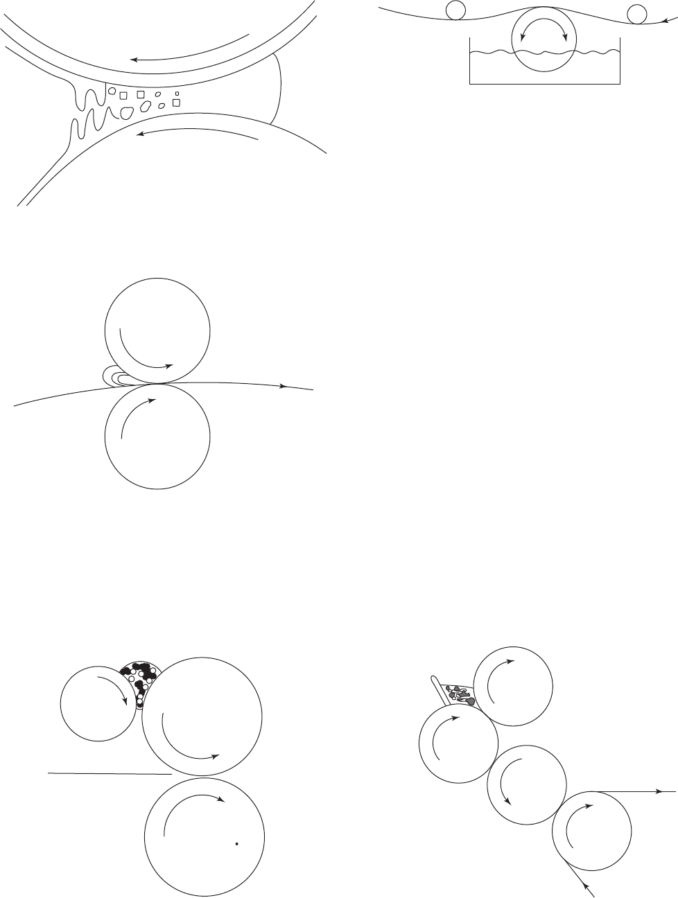
Figure 2. Coating splitting.
+
+
Figure 3. Squeeze coater.
Metering
roll
+
+
+
Applicato
r
roll
Carrier
roll
Figure 4. Direct roll sheet coater.
+
Figure 5. Kiss-roll coater.
Matering
roll
Transfer
roll
Rubber
applicator roll
Steel
backup roll
+
+
+
+
Figure 6. Transfer coater.
288 COATING EQUIPMENT

accurately the amount of substance applied on the web
(i.e. the thickness of dry coatings) as well as its homo-
geneity. It is agreed that gravure coating represents the
most uniform and reproducible system to coat moving web
of material. An engraved chrome-plated (sometimes cera-
mic coated) copper roll is wetted with the coating, excess is
removed by a doctor knife (scraper) (Figure 8), and the
coating remaining in the engraved cells below the roll
surface is transferred to the web at the gravure roll/
backup roll nip (Figure 9). Three engraving patterns are
commonly used for coating purposes: pyramidal, quadran-
gular (truncated pyramid), and tri-helical. The amount of
coating depends on the liquid volume retained in the
cells—that is, on the cell depth and their density, referred
to as screen or ruling (the number of cells per unit length).
The coarser the screen, the larger the diameter and depth
of cells and the higher the deposit. It is important that
the amount of coating entrapped in the depressions of the
gravure roll remains constant over the life of the roll,
guaranteeing a virtual constant uniformity during the
whole production process. The fluid viscosity must be
sufficiently low to allow the transfer of the coating from
the cells to the web at nip pressure. Thickness typically
ranges between 3 and 25 mm, even if lower values (0.5 mm)
can be easily obtained. In the direct gravure arrangement
(Figure 9), the engraved roll contacts the web directly. In
offset gravure the coating is first transferred to a rubber-
covered roll and then transferred to the web. In this case,
it should be important to use a covering elastomer resis-
tant to solvents eventually present in the coating solution.
Offset gravure allows the use of higher nip pressure and
is therefore more suitable for coating rough-surface
substrates. It also allows the coating to level on the roll
surface before its transfer to the web. Different matrices,
substances, and formulations can be used as coatings to be
applied through this system. Latexes, solvent-based coat-
ings, water-based coatings, hot melts, and reactive (cur-
ing) coatings are the most frequently employed. Gravure
coating is widely used for various decorative and func-
tional lightweight coatings on plastic films, paper, and
other packaging substrates. The same technique is suita-
ble for printing, wherein coating deposition takes place
only to limited areas of the substrate. In this case, a given
roll delivers a fixed amount of coating; that is, it deposits
noncontinuous coating.
The most recent machines are able to handle different
substrates continuously—that is, without arresting the
whole plant in order to substitute the coated roll with
another one. Hence, the coating application can take place
by replacing automatically online the just-coated web with
a new one previously mounted on the machine (Figure 10).
Obviously, to avoid the stop of the coating line, the
different rolls must have the same width and have to be
coated with the same matrix. The final result will be the
increased line speed in the coating process and the
enhancement of the output.
Calender Coaters. The calendering process involves
squeezing a polymeric material between steel rolls into a
Dams
Applicator roll
Backing roll
Metering roll
Figure 7. Nip-fed reverse roll coater.
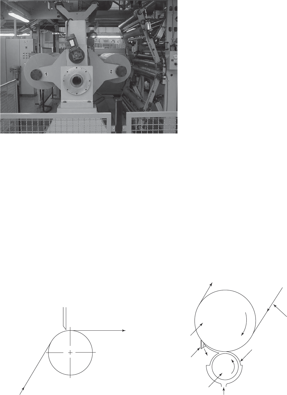
Figure 8. Gravure coater showing the doctor blade supported by
two pistons. (Courtesy of Metalvuoto Spa, Roncello, Italy.)
Idler rolls
Smoothing bar
Engraved cylinder
Pan
Doctor blade
Impression roll
Figure 9. Direct gravure coater.
COATING EQUIPMENT 289
thin sheet. The formed sheet may be then laminated to a
substrate. Rubber and PVC are most often used for
calender processing. Calendering is rarely used for man-
ufacturing packaging materials.
Knife and Bar Coaters
Knife and bar coaters are metering devices that remove
excess coating and allow only a predetermined amount to
pass through.
Knife-over-Roll Coaters. Knife-over-roll is a useful in-
expensive method for the application of coating, having
both high viscosity and heavy weights. As a result, it is
primarily used to coat paper and textiles. A knife-over-roll
coater consists of a knife placed against a roll. The knife
may be either straight-edged or ‘‘J’’-shaped, depending on
the specific application. The coating weight is adjusted by
setting a gap between the roll and the knife. An excess
coating is delivered to the bank before the knife, and the
desired amount is metered by the gap. An accurately
machined steel roll and knife are used (Figure 11). In
another version of a knife-over-roll coater, a rubber-cov-
ered roll is used and the coating weight is determined by
the gap and rubber hardness (its capability to deform
because of hydraulic pressure).
Other Knife Coaters. Knife coaters are used in many
other configurations: floating knife, knife-over-blanket,
knife-over-channel, and inverted knife. These methods
are used more frequently in the textile industry.
Blade Coating. Flexible-blade coating is the dominant
process for applying pigment coating over paper and
board. Clay coatings give a smooth and printable surface.
Blade coating processes are suitable for high-speed appli-
cation such as required in paper converting. The coating
head consists of a coating applicator, such as roll or
fountain, which applies an excess of coating to the paper.
The excess coating is removed by a blade (Figure 12).
Figure 10. Two rolls simultaneously placed on the
same coating line. Roll 2 (working) will be automati-
cally substituted by roll 1 (not working). (Courtesy of
Metalvuoto Spa, Roncello, Italy.)
Figure 11. Knife-over-roll coater.
Pape
r
Coating color
Applicator roll
Blade
Backing roll
Figure 12. Blade coater.
290 COATING EQUIPMENT

Several modifications of blade coaters are available em-
ploying different blade designs, different methods of ap-
plying and regulating blade pressure, and different ways
of applying the coating to the paper. Machines capable of
applying coating to both sides of the web are available.
The air-knife system consists of a head with a narrow
slot emitting a ribbon of pressurized air through nearly
the width of the web being coated. In air-knife coating an
excess of material is applied to the web surface usually by
a kiss-roll applicator or by spraying as a wet matrix to be
dried as quickly as possible. The excess is removed by the
air knife, wherein pressurized air is forced into the head
and is accelerated at the slotted nozzle. The escaping air-
stream impinges on the coated web and removes excess
coating (Figure 13). Air-knife coaters provide an even
thickness of the coating rather than a flat-surfaced coat-
ing. It is the preferred method for coating paper, although
in the recent years it is being replaced by more developed
blade coaters for paper-coating applications.
Wirewound-Rod Coater. A wirewound-rod coater (Meyer
rod) is a simple metering device widely used in applying
lightweight coatings over film and paper packaging mate-
rials. The coating is firstly applied by an applicator, usually
a kiss roll, and then uniformly spread by a rod wound
spirally with stainless-steel wire; finally, the excess of
coating is removed by the scraping action of the rod.
Usually, the wire-wound rod is rotated counter to the
rotation of the web, allowing a more precise control of the
process. Moreover, the rod is rotated to help dislodge any
particles that might become trapped between the wire and
the web and to ensure uniform wear of the wire. The rod
wipes the surface clean, except what escapes through the
spaces between the wires. The thickness of the wet coating
can be easily established by selecting the diameter of the
wire winding on the rod. In particular, the following
equation can be taken into consideration for this purpose:
K ¼ D 0:5
p
8
¼ 0:1073ðDÞ
where K and D are, respectively, the thickness of the wet
coating and the diameter of the wire, expressed in the same
units. As it can be seen, K is practically 10 times less than
D. It means that, for instance, a wire 125 mm in diameter
will spread a wet coating 12.5 mm thick. In some cases a rod
wound with two wires could be used, with the second one of
lesser diameter than the first. This allows us to spread
coatings thicker (about 500 mm) than those obtained by
using a single wire and to provide for coatings that flatten
out faster. Wire rod coating is particularly useful to lay
down thin layers of PVDC latex to paper. In general, paper
should not be extensible, to avoid the fact that the tension
developed to hold the web tightly against the rod coater will
stretch the extensible film (such as a polyolefin) enough to
jeopardize the process. On the contrary, stiff plastic films
like PET as well as cellophane, papers, and paperboards are
suitable to be worked in rod coaters.
Hot Melt Coating
Hot melting coating concerns the application of molten
polymers characterized by an intermediate molecular
weight. It can be considered as a variation of extrusion
coating. Both processes use a heated coating material to be
applied onto a moving web. The major difference is linked
to the viscosities, much lower for the hot melting coating.
Another further difference concerns the magnitude of
pressure applied during deposition of the coating. In
fact, hot melts are applied with little pressure. Different
materials can be used in the hot melting process, such as
waxes, resins, and thermoplastics of low molecular weight.
However, blends of polyolefins and poly(ethylene-vinyl
acetate) with resins and waxes represent the majority of
applications in food packaging. In particular, these hot
melts are widely used to obtain (a) heavy coatings to
wrapping cases for waterproofing and (b) lighter layers
to food cartons for frozen foods. Typical hot melt coating
methods include: slot-orifice coating, curtain coating, and
roll coating.
Slot-Orifice Coating. In the slot-orifice coating, the
coating is forced through a narrow slot extending
the full width of the web. The slot die is designed to give
a uniform coating thickness across the width. A slot-orifice
coater is widely used for manufacturing hot-melt
Applicator
Air knife
Excess-coating
collector
Figure 13. Air-knife coater.
COATING EQUIPMENT 291

pressure-sensitive adhesive packaging tapes (13) and for
applying waterproof coatings over paper. It also found
applications in aqueous emulsion coating. A slot orifice
coater is shown in Figure 14.
Curtain Coating. Curtain coating is similar to slot-or-
ifice coating, except that the liquid curtain coming from
the die is allowed to drop down some distance to the
material to be coated. The slot width is adjustable and
the flow is regulated by the slot width, by the liquid level
(in weir-type coaters), or by pressure and pump speed in
enclosed-head coaters, as well as by the distance between
the slot and the coated material, which determines the
acceleration of the curtain. This technique is used for
heavier coatings. In the packaging area, curtain coating
may be employed to deposit a hot wax coating over
corrugated board.
Roll Coating. Both direct and reverse roll methods can
be used for the application of hot melt coatings to the
substrate. Moreover, the rolls used for spreading the
coatings can be either smooth or engraved.
The application of the hot coatings usually takes place
at speeds ranging from 100 to 500 m min
1
at coating
weights of 3 to 600 g m
2
.
SATURATORS
The saturation or impregnation process is used to treat
paper and paperboard with a polymeric binder to improve
the web’s strength, barrier properties as packaging mate-
rial, and resistance to water and grease. The process
consists of immersion of the web into a coating bath, or
applying an excess of coating on both sides and then
squeezing or scraping to remove the excess. The coating
may penetrate the web or most of it may remain on the
surface, depending on the product needs.
Saturating machines consist of a web-immersion sec-
tion and a metering section. Several saturating arrange-
ments are used. Figure 15 shows a conventional sawtooth
saturator followed by squeeze-roll metering. Other types
of metering arrangements are inflatable bars, bar scra-
pers, doctor blades, and similar devices.
DRYING
Coatings applied as solutions or emulsions must be dried
in order to remove the liquid vehicle. Heat and mass
transfer take place simultaneously during the drying
process. Different methods are used in commercial prac-
tice, including convection drying with heated air; hot air
impingement; infrared; conduction heating; and radio-
frequency heating.
In the convection drying method, the wet web is passed
through a tunnel oven heated by a flux of hot air forced in
the same direction (sometimes in the opposite direction) as
the web.
Impingement drying consists of a forced air flux able to
dry the wet web more rapidly than convection drying. This
is because the method exploits the increased heat transfer
achieved by blowing rapidly heated air over the web
surface.
Infrared drying is carried out by using a heating source
emitting infrared rays. Indeed, infrared radiation is
usually used in combination with convection and impinge-
ment drying, to raise quickly surface temperatures and
hence to increase the efficiency of the solvent removal by
forced air.
++
+
+
+
+
Figure 15. Sawtooth saturator.
Web path
Driven, rubber-covered, backing roll
Die orifice and metering blade adjustments
Die
Die positioning adjustment
relative to web
Angular attitude adjustment of die
Pneumatic raise/lower loading cylinders
Drip tray
Figure 14. Hot-melt slot-orifice coater. (Courtesy of
Black Clawson Co.)
292 COATING EQUIPMENT

Conduction drying is obtained by the direct contact of
the web with a heated surface. The final dried substrate
(paper, paperboard, pulp, and laminations of porous webs)
is generally obtained very quickly, usually using heated
rotating cylinders.
Radio frequency (or dielectric heating) is a powerful
drying method especially for heavy coatings and water-
based systems.
Drying is a fundamental step in the coating process.
Incomplete or partial drying could lead to serious pro-
blems affecting the further converting phases, such as
bubble formation between layers, haziness, and separa-
tion of layers, among others. It is also to avoid the over-
drying a web.
The drying equipment also has a means of vapor
removal and recirculating and heat-exchange equipment
to conserve energy. Figure 16 schematically shows the
airflow in a convection dryer. If a coating from a solution
in an organic solvent is used, the solvent vapor must
be removed from the exhaust in order to satisfy the
environmental laws and to decrease solvent costs. Solvent
adsorption on activated carbon, incineration, or condensa-
tion in an inert-gas dryer are used. Drying equipment (see
also Figures 17 and 18) may be subdivided according to
the heat-transfer mechanism or according to web hand-
ling as listed in Table 2.
Extruded, hot-melt, and wax coatings do not require
drying and are solidified by chilling. Such coating ma-
chines require considerably less space than do the coating
lines with drying ovens.
Some coatings are applied as reactive monomers or
polymer/oligomer/monomer blends and may be cured by
either ultraviolet or electron-beam irradiation. Such irra-
diation units are incorporated into the coating line.
WEB HANDLING
Coating machines may apply the coating or the adhesive
to the packaging material supplied as a continuous web on
Supply
fan
Makeup
air
Combustion
air
Exhaust
fan
Dryer nozzle section
Heater
Figure 16. Airflow in a convection oven.
Figure 17. Coating line, with the extensive overhead convection
dryer system. (Courtesy of Metalvuoto Spa, Roncello, Italy.)
Figure 18. In-line infrared drying equipment (enlightened part).
Note the engraved chrome-plated roll partially covered by the
metallic pan. (Courtesy of Metalvuoto Spa, Roncello, Italy.)
COATING EQUIPMENT 293

a roll, and the finished product is rewound after comple-
tion of the operation (see Roll Handling). Unwind and
rewind stands, web-carrying equipment, and web controls
and other accessories are used (14). Controls are needed to
track the web properly on the machine and may consist of
tension-sensing devices and means of controlling the
tension and of edge-sensing devices and means of keeping
the web centered on the coating machine. Many packaging
materials are coated as sheet, requiring sheet-feeding and
sheet-handling devices. There is less of a choice between
various coating heads for sheet coating.
BIBLIOGRAPHY
1. D. Satas, Web Processing and Converting Technology and
Equipment, Van Nostrand Reinhold, New York, 1984.
2. H. L. Weiss, Coating and Laminating Machines, Converting
Technology Co., Milwaukee, WI, 1977.
3. G. L. Booth, Coating Equipment and Processes, Lockwood
Publishing, New York, 1970.
4. E. D. Cohen and E. B. Gutoff, Modern Coating and Drying
Technology, VCH Publishers, New York, 1992.
5. W. E. Brown, Plastics in Food Packaging: Properties, Design,
and Fabrication, Marcel, Dekker, New York, 1992.
6. S. E. M. Selke, J. D. Culter and R. J. Hernandez, Plastics
Packaging: Properties, Processing, Applications, and Regula-
tions, 2nd edition, Hanser Carl, Munich, 2004.
7. G. L. Robertson, Food Packaging: Principles and Practice,
Marcel, Dekker, New York, 1993.
8. A. A. Tracton, Coatings Technology Handbook, Taylor &
Francis, Boca Raton, FL, 2006.
9. R. Ryntz and P. Yaneff, Coatings of Polymers and Plastics,
Marcel, Dekker, New York, 2003.
10. M. J. Forrest, Coatings and Inks for Food Contact Materials,
Rapra Review Report, Vol. 16, No. 6, Report 186, 2007.
11. ASTM, Standard Test Method for Wetting Tension of Poly-
ethylene and Polypropylene Films, D 2578-84, Book of Stan-
dard, 08.03, Plastics, American Society for Testing and
Materials, Philadelphia, 1988.
12. T. W. Sprecher, ‘‘Testing Corona Treatments’’, Paper, Film and
Foil Converter 57(11), 114, 1983.
13. D. Satas, Handbook of Pressure Sensitive Adhesive Technol-
ogy, Van Nostrand Reinhold, New York, 1982.
14. D. R. Roisum, The Mechanics of Winding, TAPPI Press,
Atlanta, 1994.
CODE, BAR
HENRI BARTHEL
GS1 Global Office, Brussels,
Belgium
A bar code may be defined as a series of bars and spaces
arranged according to the encodation rules of a particular
specification in order to represent data. Its purpose is to
represent information in a form that is machine-readable.
Bar codes are read by scanning devices that are pro-
grammed to analyze the structure of the bars and spaces
and transmit the encoded data in electronic format. These
data can then be stored on a file or transmitted to a
computer for processing.
Techniques other than bar codes achieve the same
objective: capturing automatically data encoded using a
particular technology. These include optical character
recognition, magnetic stripe, and radio-frequency identi-
fication. The concept of encoding and reading data auto-
matically is called automatic data capture (ADC).
BENEFITS OF BAR CODES
The main benefits of bar codes are speed and accuracy.
Capturing data automatically by reading a bar code can be
done in a fraction of a second, much faster than manual
key entry. It is commonly agreed that an operator doing
key entry makes one error for every 300 characters typed.
Reading bar codes makes data capture almost error-free.
The error rate depends on the type of bar code and
equipment being used, but usually it is lower than one
error per 1,000,000 readings.
BAR-CODE SYMBOLOGIES
A bar-code symbology is a set of rules describing the way
bar and spaces have to be organized to encode data
characters.
Since the invention of the bar code concept in the
United States in the late 1950s, hundreds of bar-code
symbologies have been developed, but only a few of them
are actually being used on a large scale.
Typically, a symbology is qualified as being discrete or
continuous. In a discrete symbology, the spaces between
symbol characters do not contain information because
each character begins and ends with a bar. In a continuous
symbology, there is no intercharacter gap; that is, the final
element of one symbol character abuts the first element of
the next symbol character, and all the elements carry data
contiguously. The most popular bar-code symbologies are
briefly described below.
Code 39 was launched in 1975. It is widely used for
industrial applications. Code 39 is a discrete, variable-
length symbology encoding the 36 numeric and uppercase
alpha characters (A–Z, 0–9) and seven special characters:
space, dollar sign ($), percent (%), plus (+), minus (–), dot
(.), and slash (/). A symbol character is composed of nine
Table 2. Drying Equipment
Heat Transfer Web Handling
Convection dryers
Parallel air flow Idler-supported
Impingement air Conveyer dryers
Through dryers U-type dryers
Infrared radiation dryers Arch dryers
a
Near infrared (electric) Tenter frame dryers
Far infrared (electric or gas) Floater dryers
Conduction dryers
Hot roll dryers
a
An arch dryer including winding, coating, and laminating stations is
shown in Figure 16.
294 CODE, BAR
elements, five bars and four spaces. An element is either
wide or narrow. There are three wide elements and six
narrow elements in a symbol character. A Code 39 symbol
begins with a start character and ends with a stop
character. It can be read from the right to the left and
from the left to the right.
Interleaved two of five (abbreviated ITF) has been found
to be well adapted to the materials and printing conditions
frequently used on fiberboard cases. It is a continuous
symbology encoding only numeric digits. A pair of digits is
represented by five bars and five spaces. One of the pair is
represented by the dark bars and the other by the light
bars, and the dark and light bars are interleaved. Because
the digits are represented in pairs, the symbol can only
encode even number of digits. In addition to the digit
characters, there are two auxiliary characters used as
guard bars at the beginning and at the end of the digit
representation. The symbol is designed to be read bi-
directionally by fixed or portable scanners.
Code 128 was introduced in 1981 in response to the
need for a compact alphanumeric code symbol that could
be used to encode complex data. The fundamental require-
ment called for a symbology capable of being printed by
existing data-processing printers. Code 128 uniquely ad-
dresses this need with the most compact, complete, alpha-
numeric linear symbology available. In addition, Code 128
has been designed with geometric features to improve
scanner reading performance and to be self-checking.
EAN/UPC was developed in the late 1960s when
researches were conducted in the United States to im-
prove the efficiency of checkout operations in retail
stores. EAN/UPC is a continuous symbology encoding
fixed-length numeric digits. Several variants exist, known
as EAN-13, UPC-A, EAN-8, and UPC-E. In addition, the
symbology enables to encode two small symbols encoding
two and five digits. These are called add-ons because the
information they contain supplement the main symbols. A
symbol character is composed of seven modules, two bars,
and two spaces. A bar or a space is composed of one to four
modules. An EAN/UPC symbol begins and ends with a
guard pattern. In the EAN-13, UPC-A, and EAN-8 ver-
sion, a center pattern separates the symbol into segments
that can be read separately by a decoding equipment, thus
making the symbol omnidirectionally readable. The EAN/
UPC symbology is widely used to encode the identification
number of consumer products.
The symbologies described above are all linear symbol-
ogies. The symbol is always formed of a single row of
symbol characters. Since the early 1990s, two-dimensional
symbologies have been developed. Some are qualified as
multirow symbologies consisting of two or more vertically
adjacent rows of symbol characters. Others are known as
matrix symbologies, which take the form of a two-dimen-
sional graphic that is decoded in its entirety and not row
by row. Two-dimensional symbologies can encode a large
amount of data in a small amount of space.
PDF417 is a two-dimensional, stacked bar-code sym-
bology. In PDF417, the basic data unit or minimum
segment containing interpretable data is called a code-
word. Every codeword in the symbol is the exact same
physical length, and each codeword can be divided into 17
equal modules. Within every codeword, there are four bars
and four spaces. The minimum number of modules of any
bar or space is one; the maximum is six. The PDF417
symbology defines 929 distinct codewords and supports 12
modes. Each mode specifies the meaning of the codewords.
The standard modes are Extended Alpha Numeric Com-
paction Mode, Binary/ASCII Plus Mode, and Numeric
Mode. The number of data characters that can be encoded
in a PDF417 symbol depends on the mode being used. In
the extended alphanumeric compaction mode, the max-
imum number of ASCII characters per symbol is 1850. In
numeric mode, a symbol can encode a maximum of 2725
digits.
Data Matrix is a two-dimensional matrix symbology
that is made up of nominally square modules arranged
within a perimeter finder pattern. Each Data Matrix
symbol consists of data regions that contain nominally
square modules set out in a regular array. The data region,
or set of data regions and alignment patterns, is sur-
rounded by a finder pattern, and this is in turn sur-
rounded on all four sides by a quiet zone border. The
number of data characters per symbol is up to 2335
alphanumeric characters or 3116 numeric only characters.
Data Matrix Symbols are read by two-dimensional ima-
ging scanners or vision systems. Most other scanners
that are not two-dimensional imagers cannot read Data
Matrix. Data Matrix Symbols are designed for use with
applications that involve imaging scanners throughout
the supply chain.
DATA CONTENT
The purpose of bar-code applications is to capture data
automatically and to process these data in computer
applications. Rules are therefore required to specify the
way data should be encoded in a symbol. Similarly, when
reading a bar code, there must be a way to know accu-
rately what data have been captured. Three methods exist
to specify the rules of encoding and decoding data in bar-
code symbols:
1. The first method is to establish a one-to-one relation-
ship between the symbology and the data content.
In
this case, a
particular symbology is exclusively
reserved to carry certain types of data. The EAN/
UPC symbology is an example of this method. EAN/
UPC bar codes always carry a number that is a
unique identifier of the item on which the bar code is
affixed.
2. The second method is based on conventions defined
either by a party for its own applications or estab-
lished on the basis of mutual agreements between
two or more parties. The conventions describe the
symbology to be used and specific rules indicating
the way data elements are to be encoded. This
method is appropriate only in internal or closed
applications, because the rules are relevant only to
the parties agreeing to follow the convention.
3. The third method is based on the concept of data
identifiers, which are prefixes used to define data
CODE, BAR 295
fields. Each prefix uniquely identifies the meaning
and the format of the data field following it. Two sets
of identifiers have been standardized and are used
in many bar-code applications.
In the late 1980s, a body called FACT (Federation of
Automated Coding Technologies) was formed in the Uni-
ted States to examine existing standards and to produce
materials that would permit coexistence of standards
from all industries. A dictionary of FACT data identifiers
has been put together and was formally approved as an
American National Standard by the American National
Standards Institute (ANSI) in 1991. On December 31,
1992, the FACT organization was dissolved. Prior to its
dissolution, the Subcommittee 8 of Accredited Standards
Committee (ASC) MH10 agreed to continue the mainte-
nance of data identifiers. ANSI MH10 identifiers are
composed of one alpha character preceded by up to three
digits. These data identifiers usually have to be comple-
mented by industry guidelines providing additional clar-
ifications regarding the definition and format of the data
fields.
Following the requirements of their membership, EAN
International and UCC jointly developed a system of
application identifiers, permitting the encodation of a
wide range of information. EAN International and UCC
merged into one single global organisation called GS1 in
early 2005. The GS1 system is characterized by the
management of a unique identification scheme for pro-
ducts, services, and locations, by a clear and unambiguous
definition of data elements and by the strict recommenda-
tion of protected symbologies, offering a high level of
security.
When considering the use of data identifiers for their
bar-coding applications, users should consider the follow-
ing guidelines:
. Made-to-Order Products. When the products are
manufactured for and shipped to individual custo-
mers operating in a specific industry sector, the ANSI
MH10 data identifier set can be suitable.
. Products for General Distribution. When products
are traded with more than one customer and possibly
with more than one industry sector, the GS1 applica-
tion identifier set should be used.
APPLICATIONS
The bar-coding technology has gained wide acceptance in
numerous applications. Today, virtually all packages,
from the smallest units intended for sale to a consumer
to the biggest transport units, bear one or several bar
codes carrying their identification number and other data
relevant to the parties shipping, carrying, or receiving
goods.
Scanning at retail point of sale is a major application
using bar-code technology. Millions of stores around the
world have implemented scanning systems relying on the
GS1 identification number and the associated EAN/UPC
bar-code symbol. Scanning at point of sale enables us to
automatically register the sales through price-lookup files.
It also opens up the opportunity to implement a wide
range of applications such as inventory management,
automatic reordering, and sales analysis.
A rapidly growing field of applications using bar-coding
technologies lies within the supply chains. Goods ready for
shipment by a supplier are packed, and each package is
numbered and bar-coded with a unique number. Before
the physical delivery of the merchandise, the supplier
sends an electronic message to the delivery point, advising
about the arrival of the goods. This electronic message
contains the unique identification number of each package
and the description of its contents. When processed by the
receiver, the electronic message is matched against the
original purchase order and stored in a computer data-
base. When goods arrive, a bar-code reading device scans
the unique number identifying the goods, and the compu-
ter makes the link with the information previously stored.
The system is then able to show what has to be delivered,
and the actual delivery can be checked. Inventories can
then be updated automatically, because the information is
already available in electronic form.
PRINTING BAR CODES
Virtually any printing technology can be used to print bar
codes, provided that it is accurate enough to achieve the
right level of required quality. The printing processes fall
into two categories: commercial and on-site. The choice
between these two approaches is determined by the
nature of the information to be encoded and the number
of codes to be printed. Typically, if the information is static
(e.g., the identification number of a product to be placed on
a package) and if the number of codes to be printed is
large, the traditional commercial method using film mas-
ters is appropriate. If the information is variable (i.e.,
different for each item or short series of items or if the
quantity required is small), then on-site printing pro-
cesses should be used.
The commercial printing techniques use a master im-
age of the bar code on the printing plate. Film masters are
very accurate and are available on the market from
commercial companies. The printing process itself gener-
ally generates a print gain due to the ink viscosity, the
pressure of the printing plate, or the type of substrate
being printed. This print gain can be evaluated and
compensated in the film master itself by reducing the
size of the bars. The party ordering the film, the film
master supplier, and the printer must work closely to-
gether to achieve a quality bar code.
The
on-site printing techniques
may use a piece of
hardware acting as graphics controller between the com-
puter and the printer. They may also use ‘‘intelligent’’
printers incorporating the controller equipment. Finally,
software is commercially available to generate the picture
of the bar code and send it to a printer. The printing
systems may be based on character-by-character impact,
on serial dot-matrix, or on linear-array technologies. The
choice of the appropriate technology depends on many
parameters linked to the application requirements.
296 CODE, BAR
READING BAR CODES
Many types of devices are commercially available to read
bar codes. They all illuminate the symbol and analyze the
resulting reflectance. Areas of high reflectance are inter-
preted as spaces, while areas of low reflectance do represent
bars. The reflected pattern of bars and space is converted to
an electric signal that is then digitized. The decoder assigns
a binary value to the signal and forms a complete message.
The message is checked by the decoder’s software and
transformed into data according to the appropriate decod-
ing algorithm relevant to the symbology being read.
Fixed-beam readers depend on external motion to read
the symbol. This can be provided by an operator moving
the reader across the symbol or by providing movement to
the symbol in front of the reader. A low-cost popular
reading device is the handheld contact scanner. It requires
an operator to move the reader smoothly over the symbol.
Moving-beam readers use a mirrored moving surface to
provide the illumination. The light source appears as a
continuous line of light. The most common moving-beam
readers in use are generally referred to as laser scanners.
Imaging devices are also used to read bar codes. They
operate similarly to a camera. The reflected image of the
bar code is projected onto photodiodes composed of many
photodetectors. The photodetectors are sampled by a
microprocessor and produce a video signal that is then
decoded.
The choice of a reading device is dictated by many
parameters linked to the application and to economic
criteria.
BIBLIOGRAPHY
1. GS1 General Specifications, available from GS1, avenue
Louise 326, B-1050 Brussels, Belgium.
2. C. K. Harmon, Lines of Communication, Bar Code and Data
Collection Technology for the 90s, Helmers Publishing, Dublin,
NH, 1994.
3. R. C. Palmer, The Bar Code Book, Reading, Printing and
Specification of Bar Code Symbols, Helmers Publishing, Du-
blin, NH, 1991.
4. W. H. Erdei, Bar Codes, Design, Printing & Quality Control,
McGraw-Hill, Interamericana de Mexico, 1993.
COEXTRUSION FOR SEMIRIGID PACKAGING
This article pertains to a flat, semirigid coextruded sheet,
which is a minimum of 0.010 in. (0.25 mm) thick (see
Coextrusion machinery, flat). These coextruded sheet
structures are thermoformed to produce high-barrier
plastic packages (see Barrier polymers; Thermoforming).
A similar concept is used to produce high-barrier plastic
bottles, except the bottles are formed from coextruded
multilayer tubes instead of a flat sheet (see Blow molding).
The production of coextrusions for semirigid packaging
was made possible by technology developed in the late
1960s and early 1970s (1, 2). Utilization of this technology
was initially limited to ‘‘simple’’ structures, such as two-
layer systems (a general-purpose polystyrene cap layer on
a high-impact polystyrene base layer) for drink cups.
Commercialization of high-barrier coextrusions occurred
in the 1970s in Europe and Japan. Large-scale commercial
barrier coextrusion applications did not surface in
the United States until the 1980s. For the purposes of
this discussion, barrier materials are defined as those that
exhibit an oxygen transmission rate of less than
0.2 cm
3
mil/(100 in
2
day atm) [0.777 c
3
mm/(m
2
d kPa)]
(see Barrier polymers). Other techniques that can be used
to produce multilayer barrier structures are coating and
lamination (see Coating equipment; Laminating). Some
advantages coextrusion offers versus these other two
methods are thicker barrier layer capability, single-pass
production, barrier layer sandwiched between cap layers,
and generally lower cost. The potential markets for
packages formed from these high-barrier coextrusions
include both low- and high-acid food products sterilized
by aseptic, hot-fill, or retort methods. These markets
obviously represent a significant opportunity for barrier
coextrusions.
BARRIER MATERIALS
On the basis of the barrier definition above, only two
commercially available thermoplastic resins can be con-
sidered as barrier resin candidates for these extrusions:
ethylene–vinyl alcohol (EVOH) (see Ethylene–vinyl alco-
hol) and poly(vinylidene chloride) (PVDC) (see Vinylidene
chloride copolymers). The barrier properties of specific
grades of these two materials are listed in Table 1. The
resins identified in the table are currently the highest
barrier, commercially available, coextrudable resins of
their respective polymer classes. Other formulations of
both resin types are available offering certain property
and processing improvements at the sacrifice of barrier
properties.
The most significant technical issue concerning the use
of EVOH as a barrier material is its moisture sensitivity.
The material is hygroscopic, and its barrier properties are
reduced as it absorbs moisture. The importance of this
property to the food packager is dependent on the ster-
ilization process, food type packaged, and the package
storage conditions. The most severe conditions are en-
countered during retort processing (see Canning, food).
Special consideration to coextrusion structure design and
postretorting conditions may be required to achieve the
desired oxygen barrier for packages produced from EVOH
coextrusions (3).
PVDC is not moisture sensitive and does not exhibit the
deterioration of barrier properties shown by EVOH. The
challenges associated with using heat-sensitive PVDC are
faced by the coextruded sheet producer. Equipment and
process design are critical to the production of coextru-
sions containing PVDC. Concern relating to the reuse of
scrap generated in the production of coextrusions based on
COEXTRUSION FOR SEMIRIGID PACKAGING 297