Yu W., LaBoube R.A. Cold-Formed Steel Design
Подождите немного. Документ загружается.

BENDING STRENGTH AND DEFLECTION 105
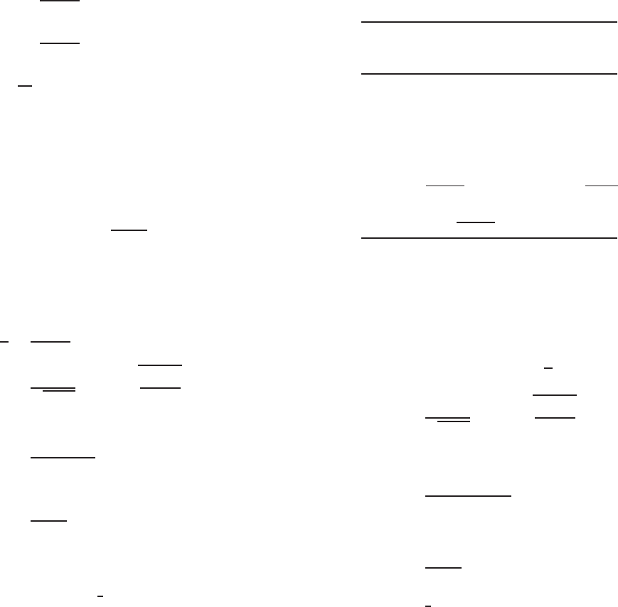
From Fig. 4.6,
f
1
= 50
5.2302
5.399
= 48.44 ksi (compression)
f
2
= 50
4.4322
5.399
= 41.05 ksi (tension)
ψ =
f
2
f
1
= 0.847
k = 4 + 2(1 + ψ)
3
+ 2(1 + ψ) = 20.30
From Fig 4.4, the out-to-out web depth
h
0
= 10.00 in. and the out-to-out compression
flange width b
0
= 3.50 in. Since h
0
/b
0
=
10.00/3.50 = 2.86 < 4, use Eq. (3.55a),
b
1
=
b
e
3 + ψ
where b
e
is the effective width of the web deter-
mined in accordance with Eqs. (3.41)–(3.44)
with f
1
substitued for f and k = 20.30 as
follows:
h
t
=
9.6624
0.075
= 128.83 < 200 OK
λ =
1.052
√
20.30
(128.83)
48.44
29,500
= 1.219 > 0.673
ρ =
1 − 0.22/λ
λ
= 0.672
b
e
= ρh = 0.672 × 9.6624 = 6.4931 in.
b
1
=
b
e
3 + ψ
= 1.6878 in.
Because ψ>0.236, Eq. (3.55b)isusedto
compute b
2
:
b
2
=
1
2
b
e
= 3.2465 in.
b
1
+ b
2
= 4.9343 in.
Since the value of b
1
+ b
2
is less than 5.2302 in.
shown in Fig. 4.6, the web element is not fully
effective as assumed. The neutral axis should be
relocated by using the partially effective web.
The procedure is iterative as illustrated below.
b. Location of Neutral Axis Based on Ineffective
Web Eleme nt s . As the first iteration, the inef-
fective portion of the web can be assumed as
follows:
5.2302 − (b
1
+ b
2
) = 5.2302 − 4.9343
= 0.2959 in.
Therefore, the effective lengths of all e lements
are s hown in Fig. 4.7 using partially effective
web.
Effective Distance from
Length L Top Fiber yLy
Element (in.) (in.) (in
2
.)
1 0.5512 9.5556 5.2670
2 0.4120 9.9148 4.0849
3 3.1624 9.9625 31.5054
4 0.4120 0.0852 0.0351
5 2.2300 0.0375 0.0836
6 0.1130 0.2254 0.0255
7 7.6787 5.9919 46.0100
8
1.6878 1.0127 1.7092
16.2471 88.7207
y
cg
=
88.7207
16.2471
= 5.461 in.
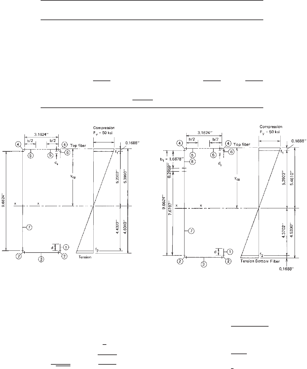
From Fig. 4.7,
f
1
= 48.45 ksi (compression)
f
2
= 40.01 ksi (tension)
ψ = 0.826 k = 19.83
h
t
= 128.83
λ =
1.052
√
19.83
(128.83)
48.45
29,500
= 1.233 > 0.673
ρ =
1 − 0.22/1.233
1.233
= 0.666
b
e
= ρh = 6.4352 in.
b
1
=
b
e
3 + ψ
= 1.6820 in.
b
2
=
1
2
b
e
= 3.2176 in.
b
1
+ b
2
= 4.8996 in.
Because the above computed value of b
1
+ b
2
is less than the previous value of 4.9343 in. by
0.7%, additional iterations are required.
For the second iteration, the ineffective
portion of the web is
5.2922 − (b
1
+ b
2
) = 5.2922 − 4.8966
= 0.3926 in.
By using the same procedure shown above, the
neutral axis can be relocated as follows:
106 4 FLEXURAL MEMBERS
Effective Length Distance from
Element L (in.) Top Fiber y (in.) Ly (in.
2
) Ly
2
(in.
3
)
1 0.5512 9.5556 5.2670 50.3298
2 0.4120 9.9148 4.0849 40.5009
3 3.1624 9.9625 31.5054 313.8727
4 0.4120 0.0852 0.0351 0.0030
5 2.2300 0.0375 0.0836 0.0031
6 0.1130 0.2254 0.0057 0.0057
7 7.5878 6.0373 45.8098 276.5675
8
1.6820 1.0098 1.6985 1.7151
16.1504 88.5098 682.9977
y
cg
=
88.5098
16.1504
= 5.481 in.
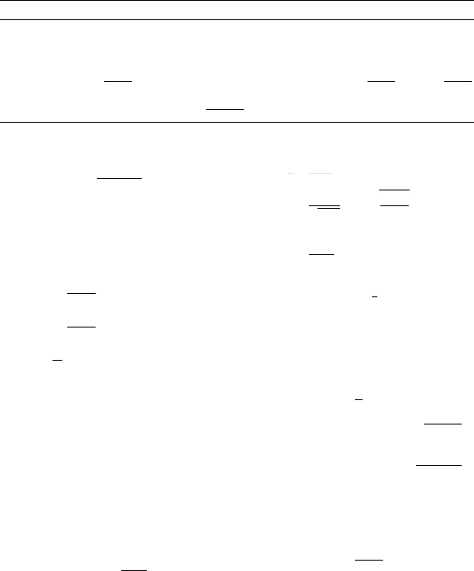
Figure 4.6 Effective lengths and stress distribution using
fully effective web.
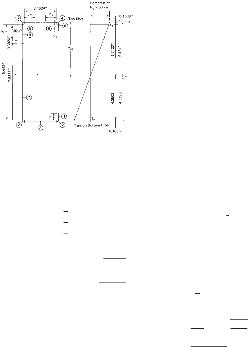
From Fig. 4.8,
f
1
= 48.46 ksi (compression)
f
2
= 39.68 ksi (tension)
ψ = 0.819 k = 19.68
h
t
= 128.83
λ =
1.052
√
19.68
(128.83)
48.46
29,500
= 1.238 > 0.673
Figure 4.7 Effective lengths and stress distribution using
partially effective web (first iteration).
ρ =
1 − 0.22/1.238
1.238
= 0.664
b
e
= ρh = 6.4158 in.
b
1
=
b
e
3 + ψ
= 1.6800 in.
b
2
=
1
2
b
e
= 3.2079 in.
b
1
+ b
2
= 4.8879 in.
BENDING STRENGTH AND DEFLECTION 107
Figure 4.8 Effective lengths and stress distribution using
partially effective web (second interaction).
Because the above computed value of b
1
+ b
2
is approximately equal to the value of b
1
+ b
2
computed from the first iteration, it is accept-
able. Better accuracy can be obtained by using
additional iterations.
c. Moment of Inertia and Section Modulus. The
moment of inertia based on line elements is
I
1
=
1
12
(0.5512)
3
= 0.0140
I
6
=
1
12
(0.113)
3
= 0.0001
I
7
=
1
12
(7.5878)
3
= 36.4054
I
8
=
1
12
(1.6820)
3
= 0.3965
(Ly
2
) = 682.9977
I
z
= 719.8137 in.
3
−
L
(y
cg
)
2
=−(16.1504)(5.481)
2
=−485.1800
I
x
= 234.6337 in.
3
I
x
= I
x
t = (234.6337)(0.075) = 17.598 in.
4
S
x
=
17.598
5.481
= 3.211 in.
3
2. Nominal and Allowable Moments. The nominal
moment for section strength is
M
n
= S
e
F
y
= S
x
F
y
= 3.211(50)
= 160.55 in.-kips
The allowable moment is
M
a
=
M
n
b
=
160.55
1.67
= 96.14 in.-kips
B. LRFD Method.
The nominal moment for the LRFD method is the same a s
that computed for the ASD method. From item A above,
the nominal moment about the x axis of the C-section is
M
n
= 160.55 in.-kips
Based on Section 4.2.1 or Section C3.1.1 of the North
American Specification, the design moment for the C-
section having a partially stiffened compression flange
(φ
b
= 0.95) is
φ
b
M
n
= 0.95(160.55) = 152.52 in.-kips
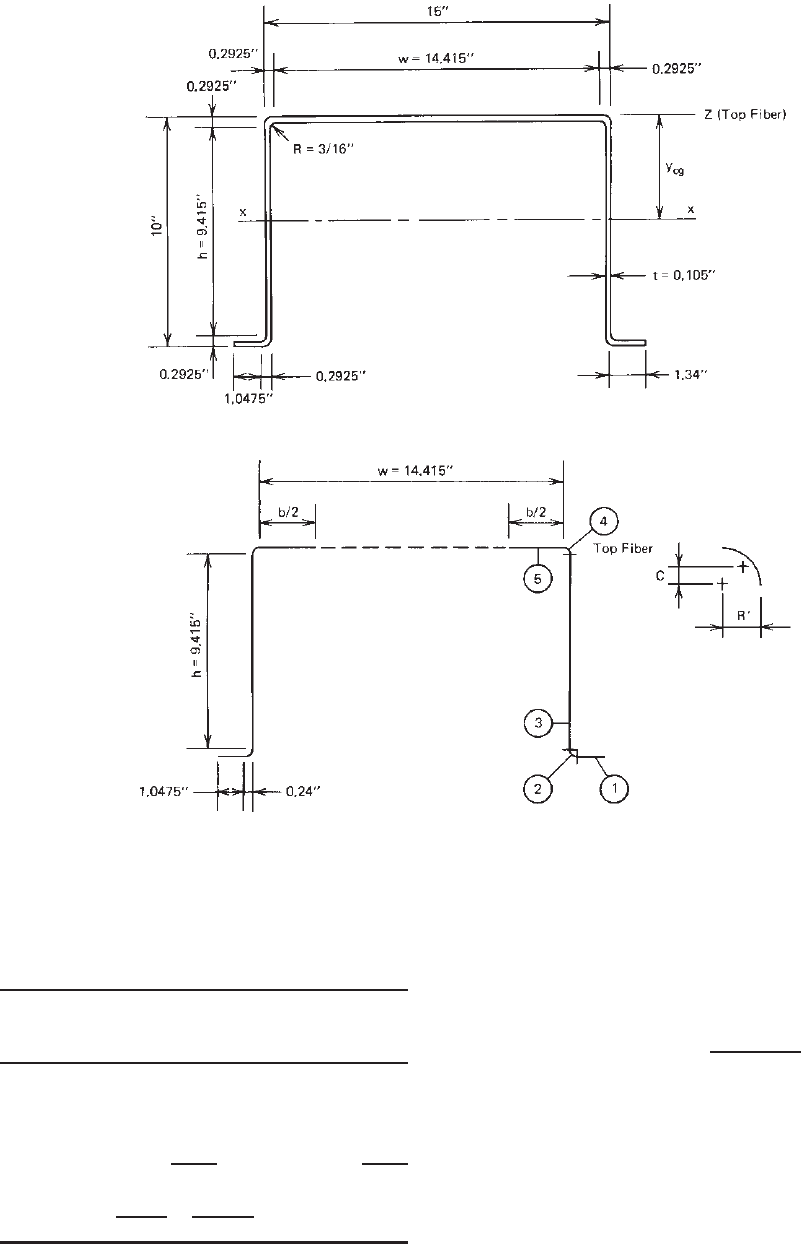
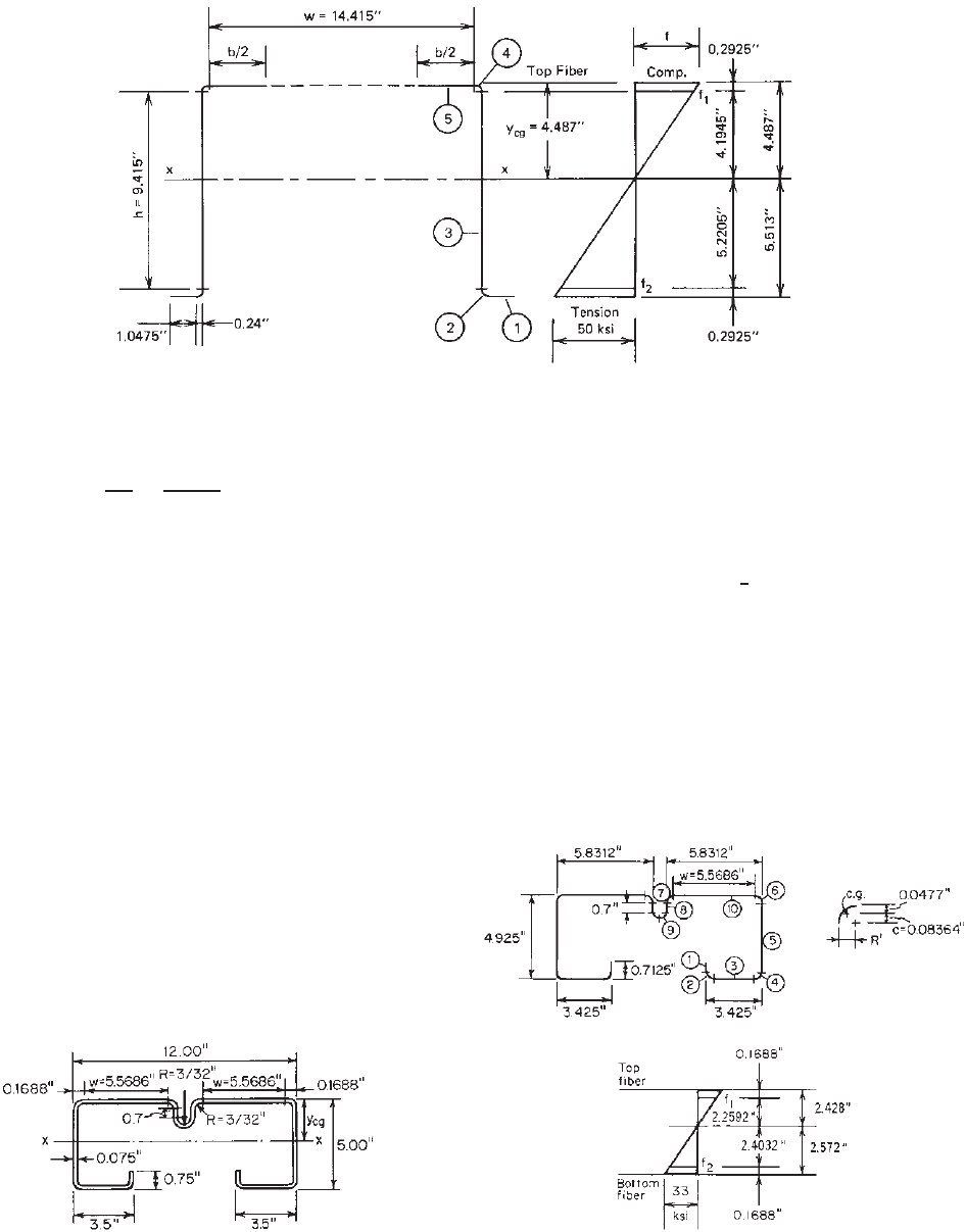
Example 4.3 For the hat section w ith a stiffened compres-
sion flange as shown in Fig. 4.9, determine the allowable
moment (M
a
) about the x axis for the ASD method and the
design moment (φ
b
M
n
) for the LRFD method. Assume that
the yield stress of steel is 50 ksi. Use the linear method. The
nominal moment is determined by initiation of yielding.
SOLUTION
A. ASD Method
1. Calculation of Sectional Properties. In order to use
the linear method, midline dimensions are shown in
Fig. 4.10.
i. Corner Element (Figs. 1.32 and 4.10)
R
= R +
1
2
t = 0.240 in.
Arc length:
L = 1.57R
= 0.3768 in.
c = 0.637R
= 0.1529 in.
ii. Location of Neutral Axis
a. First Approximation. For the compression
flange,
w = 15 − 2(R + t) = 14.415 in.
w
t
= 137.29
Using Eqs. (3.41)–(3.44) and assuming f =
F
y
= 50 ksi,
λ =
1.052
√
4
(137.29)
50
29,500
= 2.973 > 0.673
ρ =
1 − 0.22/2.973
2.973
= 0.311
b = ρw = 0.311(14.415) = 4.483 in.
108 4 FLEXURAL MEMBERS
Figure 4.9 Example 4.3.
Figure 4.10 Line elements.
By using the effective width of the compression
flange and assuming that the web is fully effec-
tive, the neutral axis can be located as follows:
Distance from
Effective Length L Top Fiber y
Element (in.) (in.) Ly (in.
2
)
12× 1.0475 = 2.0950 9.9475 20.8400
22× 0.3768 = 0.7536 9.8604 7.4308
32× 9.4150 = 18.8300 5.0000 94.1500
42× 0.3768 = 0.7536 0.1396 0.1052
5
4.4830 0.0525 0.2354
Total 26.9152 122.7614
y
cg
=
(Ly)
L
=
122.7614
26.9152
= 4.561 in.
Because the distance y
cg
is less than the half
depth of 5.0 in., the neutral axis is closer
to the compression flange and, therefore, the
maximum stress occurs in the tension flange.
The maximum compressive stress can be
computed as follows:
f = 50
4.561
10 − 4.561
= 41.93 ksi
Since the above computed stress is less than the
assumed value, another trial is required.
b. Second Approximation. After several trials,
assume that
f = 40.70 ksi λ = 2.682 > 0.673
b = 4.934 in.
BENDING STRENGTH AND DEFLECTION 109
Element Effective Length L (in.) Distance from Top Fiber y (in.) Ly (in.
2
) Ly
2
(in.
3
)
1 2.0950 9.9475 20.8400 207.3059
2 0.7536 9.8604 7.4308 73.2707
3 18.8300 5.0000 94.1500 470.7500
4 0.7536 0.1396 0.1052 0.0147
5
4.9340 0.0525 0.2590 0.0136
Total 27.3662 122.7850 751.3549
y
cg
=
122.7850
27.3662
= 4.487 in.
that is,
f = 50
4.487
10 − 4.487
= 40.69 ksi
Since the above computed stress is close to the
assumed value, it is OK.
iii. Check the Effectiveness of the Web. Use Section
3.5.1.2 in this volume or B2.3 of the North Amer-
ican specification to check the effectiveness of the
web element. From Fig. 4.11,
f
1
= 50
4.1945
5.513
= 38.04 ksi (compression)
f
2
= 50
5.2205
5.513
= 47.35 ksi (tension)
ψ =
f
2
f
1
= 1.245
k = 4 + 2(1 + ψ)
3
+ 2(1 + ψ)
= 4 +2(2.245)
3
+ 2(2.245) = 31.12
From Fig 4.9,
h
0
= out-to-out depth of web
= 10.00 in.
b
0
= out-to-out width of compression flange
= 15.00 in.
Since h
0
/b
0
= 10/15 = 0.667 < 4, then use Eq.
(3.55a),
b
1
=
b
e
3 + ψ
where b
e
is the effective width of the web deter-
mined in accordance with Eqs. (3.41)–(3.44) with
f
1
substitued for f and k = 31.12 as follows:
h
t
=
9.415
0.105
= 89.67 < 200 OK
λ =
1.052
√
31.12
(89.67)
38.04
29,500
= 0.607 < 0.673
b
e
= h = 9.415 in.
b
1
=
b
e
3 + ψ
= 2.218 in.
Since ψ>0.236,
b
2
=
1
2
b
e
= 4.7075 in.
b
1
+ b
2
= 6.9255 in.
Because the computed value of b
1
+ b
2
is greater
than the compression portion of the web (4.1945
in.), the web element is fully effective.
iv. Moment of Inertia and Section Modulus. The
moment of inertia based on line elements is
2I
3
= 2
1
12
(9.415)
3
= 139.0944
(Ly)
2
= 751.3549
I
z
= 890.4493 in.
3
−
L
(y
cg
)
2
=−27.3662(4.487)
2
=−550.9683 in.
3
I
x
= 339.4810 in.
3
The actual moment of inertia is
I
x
= I
x
t = (339.4810)(0.105) = 35.646 in.
4
The section modulus relative to the extreme tension
fiber is
S
x
=
35.646
5.513
= 6.466 in.
3
2. Nominal and Allowable Moments. The nominal
moment for section strength is
M
n
= S
e
F
y
= S
x
F
y
= (6.466)(50) = 323.30 in.-kips
110 4 FLEXURAL MEMBERS
Figure 4.11 Effective lengths and stress distribution using fully effective web.
Theallowablemomentis
M
a
=
M
n
b
=
323.30
1.67
= 193.59 in.-kips
B. LRFD Method.
The nominal moment for the LRFD method is the same as
that computed for the ASD method. From item A above,
the nominal moment about the x axis of the hat section is
M
n
= 323.30 in.-kips
Based on Section 4.2.1 in this volume or C3.1.1 of the
North American specification, the design moment for the
hat section having a stiffened c ompression flange (φ
b
= 0.95) is
φ
b
M
n
= 0.95(323.30) = 307.14 in.-kips
Example 4.4 For the section with an intermediate stiff-
ener as shown in Fig. 4.12, determine the allowable moment
(M
a
) about the x axis for the ASD method and the design
moment (φ
b
M
n
) for the LRFD method. Use the linear
method with F
y
= 33 ksi. The nominal moment is deter-
mined by initiation of yielding.
Figure 4.12 Example 4.4.
SOLUTION
A. ASD Method
1. Calculation of Sectional Properties. Using the linear
method as shown in Fig. 4.13.
i. Corner Element (Figs. 1.32 and 4.13)
R
= R +
1
2
t = 0.1313 in.
Arc length:
L = 1.57R
= 1.57(0.1313) = 0.2063 in.
c = 0.637R
= 0.637(0.1313) = 0.0836 in.
ii. Location of Neutral Axis Based on Section 3.5.3.2.1
in this volume or B5.1 of the North American Spec-
ification
Figure 4.13 Example 4.4; line elements.
BENDING STRENGTH AND DEFLECTION 111
a. First Approximation. For the top compression
flange,
b
o
= 12 −2(R + t) = 11.6624 in.
b
p
= w = 5.5686 in.
A
s
= [2(0.7) + 4(0.2063)](0.075)
= 0.1669 in.
2
A
g
= 2(5.5686)(0.075) + 0.1669
= 1.0022 in.
2
The moment of inertia of the full intermediate
stiffener (elements 7, 8, and 9 in Fig. 4.13) about
its own centroidal axis is given as
I
s
=
2
1
12
(0.7)
3
+ 4(0.2063)
× (0.35 + 0.0836)
2
(0.075)
= 15.923 × 10
−3
in.
4
the moment of inertia of the stiffener about the
centerline of the flat portion of the element as
I
sp
= I
s
+ A
s
(0.35 + 0.0836 +0.0477)
2
= 0.015923 + 0.1669(0.4813)
2
= 54.585 × 10
−3
in.
4
and the plate local buckling coefficient for the
subelement [Eq. (3.91)] as
k
loc
= 4
b
o
b
p
2
= 4
11.6624
5.5686
2
= 17.545
From Eqs. (3.92)–(3.95),
γ =
10.92I
sp
b
o
t
3
=
10.92(54.585 × 10
−3
)
11.6624(0.075)
3
=
0.596068
0.00492
= 121.150
δ =
A
s
b
o
t
=
0.1669
11.6624 × 0.075
= 0.1908
β = [1 + γ(n+ 1)]
1/4
= [1 + 121.150(1 + 1)]
0.25
= 3.949
k
d
= plate buckling coefficient
for distortional buckling
=
(1 + 3.949
2
)
2
+ 121.150(1 + 1)
3.949
2
(1 + 0.1908(1 +1))
= 24.027
The modification factor for the distortional
plate buckling coefficient can be computed as
follows:
h = 5 −2(R + t) = 4.6625
b
o
h
=
11.6624
4.6625
= 2.501 > 1
R =
11 − b
o
/h
5
=
11 − 2.501
5
= 1.700 >
1
2
OK
Since
Rk
d
= (1.700)(24.027)
= 40.846 >(k
loc
= 17.545)
use
k = 17.545
Then
f
cr
=
kπ
2
E
12(1 − μ
2
)(b
o
/t)
2
=
(17.545)(π
2
)(29500)
12(1 − 0.3
2
)(11.6624/0.075)
2
= 19.346 ksi
Assuming that f = F
y
= 33 ksi yields
λ =
f
f
cr
=
33
19.346
= 1.306 > 0.673
ρ =
1 − 0.22/1.306
1.306
= 0.637
From Eq. (3.85), the effective width of elements
7, 8, 9, and 10 located at the centroid of the
top flange, including the intermediate stiffener,
is given as
b
e
= ρ
A
g
t
= 0.637
1.0022
0.075
= 8.512 in.
The location of the centroid from the top fiber
of the flange is
y
7−10
=
2(5.5686)(0.075)(0.075/2)
+A
s
(0.7/2 + 3/32)
A
g
= 0.1052 in. from top fiber
112 4 FLEXURAL MEMBERS
Distance from
Effective Length Top Fiber yLy
Element L (in.) (in.) (in.
2
)
12× 0.5812 = 1.1624 4.5406 5.2780
22× 0.2063 = 0.4126 4.9148 2.0278
32× 3.1624 = 6.3248 4.9625 31.3868
42× 0.2063 = 0.4126 4.9148 2.0278
52× 4.6624 = 9.3248 2.5000 23.3120
62× 0.2063 = 0.4126 0.0852 0.0352
7–10
8.5120 0.1052 0.8955
Total 26.5618 64.9631
y
cg
=
(Ly)
L
=
64.9631
26.5618
= 2.446 < 2.50 in.
f =
2.446
5 − 2.446
(33) = 31.60 ksi
Since the computed value is considerably less
than 33 ksi, additional trials are required. After
several trials, it was found that the stress should
be about 31.10 ksi.
b. Additional Approximation. Assume
f = 31.10 ksi
λ = 1.268 > 0.673
b
e
= 8.712 in.
y
7−10
= 0.1052 in. from top fiber
Effective Distance from
Length Top Fiber yLy Ly
2
Element L (in.) (in.) (in.
2
)(in.
3
)
1 1.1624 4.5406 5.2780 23.9653
2 0.4126 4.9148 2.0278 9.9664
3 6.3248 4.9625 31.3868 155.7570
4 0.4126 4.9148 2.0278 9.9664
5 9.3248 2.5000 23.3120 58.2800
6 0.4126 0.0852 0.0352 0.0030
7–10
8.7120 0.1052 0.9165 0.0964
Total 26.7618 64.9841 258.0345
y
cg
=
64.9841
26.7618
= 2.428 in.
2
f =
2.428
5 − 2.428
(33) = 31.15 ksi
Since the computed stress is close to the
assumed value of 31.10 ksi, it is OK.
To check if the web is fully effective, refer to
Fig. 4.13:
f
1
= 33
2.2592
2.572
= 28.99 ksi (compression)
f
2
= 33
2.4032
2.572
= 30.83 ksi (tension)
ψ =
f
2
f
1
= 1.063
k = 4 + 2(1 + ψ)
3
+ 2(1 + ψ) = 25.69
From Fig 4.12,
h
0
= out-to-out depth of web
= 5.00 in.
b
0
= out-to-out width of compression flange
= 12.00 in.
Since h
0
/b
0
= 5/12 = 0.417 < 4, then use Eq.
(3.55a),
b
1
=
b
e
3 + ψ
where b
e
is the effective width of the web deter-
mined in accordance with Eqs. (3.41)–(3.44)
with f
1
substitued for f and k = 25.69 as
follows:
h
t
=
4.6624
0.075
= 62.17 < 200 OK
λ =
1.052
√
25.69
(62.17)
28.99
29,500
= 0.405 < 0.673
b
e
= h = 4.6624 in.
b
1
=
b
e
3 + ψ
=
4.6624
4.063
= 1.148 in.
Since ψ>0.236,
b
2
=
1
2
b
e
= 2.3312 in.
b
1
+ b
2
= 3.4792 > 2.2592 in.
The web is fully effective as assumed.
BENDING STRENGTH AND DEFLECTION 113
iii. To tal I
x
and S
x
.
2I
5
= 2 ×
1
12
× (4.6624)
3
= 16.8918
2I
1
= 2 ×
1
12
× (0.5812)
3
= 0.0327
2(I
2
+ I
4
+ I
6
) = 0.0020
(Ly
2
) = 258.0345
274.9610
−
L
y
cg
2
=−26.7618(2.428)
2
=−157.7657
I
x
= 117.1953 in.
3
I
x
= I
x
t = 117.1953(0.075) = 8.7896 in.
4
S
x
=
8.7896
5 − 2.428
= 3.4174 in.
3
2. Nominal and Allowable Moments. The nominal
moment for section strength is
M
n
= S
e
F
y
= S
x
F
y
= (3.4174)(33) = 112.774 in.-kips
Theallowablemomentis
M
a
=
M
n
b
=
112.774
1.67
= 67.53 in.-kips
B. LRFD Method.
The nominal moment for the LRFD method is the same
as that computed for the ASD method. From the above
calculations, the nominal moment about the x axis of the
section is
M
n
= 112.774 in.-kips
Based on Section 4.2.1 in this volume or C3.1.1 of the
North American specification, the design moment for the
given section having a uniformly compressed flange with
one intermediate stiffener (φ
b
= 0.95) is
φ
b
M
n
= 0.95(112.774) = 107.14 in.-kips
4.2.2.2 Effects of Cold Work on Bending Strength The
bending strength of cold-formed steel sections discussed
above was based on the mechanical properties of the
virgin material. The effects of cold work were completely
neglected.
When the effects of cold work are utilized in the deter-
mination of bending strength, the computation can be
performed by one of the following two design approaches.
1. Consider the increase in yield stress at corners due to
cold work and neglect the effects of cold work in all
flat portions of the section. As discussed in Chapter
2, the increase in yield stress can be found either by
the use of Eq. (2.11) or by tests.
2. Consider the effects of cold work for corners and all
flat elements. Equation (2.14) can be used to compute
the average yield stress of the entire section.
In either design approach, the following procedures may be
used
2.17
:
1. Subdivide the section into a number of elements.
Assume a position of the neutral axis and the strain in
the top fiber. Compute the strains in various elements
based on the assumed neutral axis and the top fiber
strain.
2. Determine the stresses from the stress–strain rela-
tionship of the material in various elements for the
computed strains.
3. Locate the neutral axis by iteration until
σA= 0
is satisfied. Then the bending moment can be approx-
imated by
M =
σy A
where σ = stress
A = area for element
y = distance between center of gravity of
each element and neutral axis
Results of the study by Winter and U ribe indicate
that for the steels commonly used in thin-walled cold-
formed steel construction, considering the effects of
cold work only in the corners of the formed sections,
the moment capacities can be increased by 4–22%
compared with those obtained when neglecting cold
work.
2.17
If the effects of cold work are considered in both the
flats and the corners, the increase in bending strength
ranges from 17 to 41% above the virgin value.
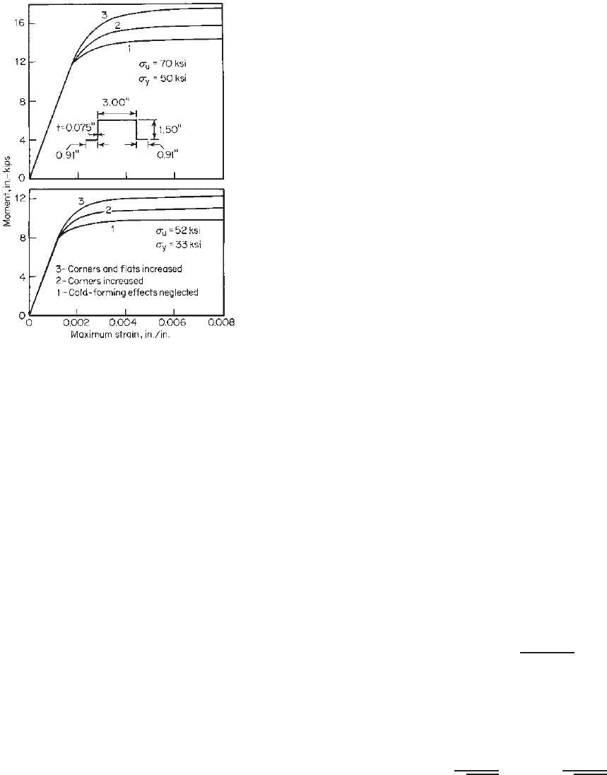
It can be seen that a substantial advantage can be
obtained by using the increase in strength of the mate-
rial. Figure 4.14, reproduced from Ref. 2.17, shows a
comparison of the ultimate moments computed for
three different conditions. It should be noted that the
effects of cold work as shown in Fig. 4.14 may not
be directly applied to other configurations because the
relative influence of corners or flats on the increase
in bending strength depends mainly on the config-
uration of the section and the spread between the
tensile strength and yield stress of the virgin mate-
rial. Attention should be given to the limitations
of Section A7.2 of the North American Specifica-
tion when the effects of cold work are used in
design.
114 4 FLEXURAL MEMBERS
Figure 4.14 Comparison of ultimate moments computed for
three d ifferent conditions.
2.17
4.2.2.3 I nelastic Reserve Capacity of Beams Prior to
1980, the inelastic reserve capacity of beams was not
included in the AISI Specification because most cold-
formed steel shapes have width-to-thickness ratios consid-
erably in excess of the limits required by plastic design.
Because of the use of large width-to-thickness ratios for the
beam flange and web, such members are usually incapable
of developing plastic hinges without local buckling.
In the 1970s research work on the inelastic strength of
cold-formed steel beams was carried out by Reck, Pekoz,
Winter, and Yener at Cornell University.
4.1–4.4
These studies
showed that the inelastic reserve strength of cold-formed
steel beams due to partial plastification of the cross section
and the moment redistribution of statically indeterminate
beams can be significant for certain practical shapes. With
proper care, this reserve strength can be utilized to achieve
more economical design of such members. In Europe, a
study has been made by von Unger on the load-carrying
capacity of transversely loaded continuous beams with thin-
walled sections, in particular of roof and floor decks with
trapezoidal profiles.
4.5
In addition, the buckling strength and
load-carrying capacity of continuous beams a nd steel decks
have also been studied by some other investigators.
4.6–4.9
In order to utilize the available inelastic reserve strength
of certain cold-formed steel beams, design provisions based
on the partial plastification of the cross section were added
in the 1980 edition of the AISI Specification. The same
provisions were retained in the 1986 and the 1996 editions
of the AISI specification and the North American Spec-
ification. According to procedure II of Section C3.1.1 of
the specification, the nominal section strengths M
n
of those
beams satisfying certain specific limitations can be deter-
mined on the basis of the inelastic reserve capacity with
a limit of 1.25M
y
or 1.25S
e
F
y
. In the above expression,
M
y
is the effective yield moment determined according to
Section 4.2.2.1 The ratio of M
n
/M
y
represents a measure
of the inelastic reserve strength of a beam cross section.
The nominal moment M
n
is the maximum bending
capacity of the beam by considering the inelastic reserve
strength through partial plastification of the cross section.
The inelastic stress distribution in the cross section depends
on the maximum strain in the compression flange, ε
cu
.
Based on the Cornell research work on hat sections
having stiffened compression flanges,
4.1
the design provi-
sion included in Section C3.1.1 of the North American
Specification limits the maximum compression strain to be
C
y
ε
y
,thatis,
cu
= C
y
y
(4.5)
where ε
y
= yield strain, =F
y
/E, in./in.
E = modulus of elasticity of steel, 29.5 × 10
3
ksi
(203 GPa or 2.07×10
6
kg/cm
2
)
F
y
= yield stress of steel, ksi
and C
y
is the compression strain factor determined as
follows:
1. Stiffened compression elements without intermediate
stiffeners:
a. When w/t ≤ λ
1
,
C
y
= 3.0 (4.6)
b. When λ
1
<w/t<λ
2
,
C
y
= 3 − 2
w/t − λ
1
λ
2
− λ
1
(4.7)
c. When w/t ≥ λ
2
,
C
y
= 1.0 (4.8)
where
λ
1
=
1.11
F
y
/E
λ
2
=
1.28
F
y
/E
The relationship between C
y
and the w/t ratio of
the compression flange is shown in Fig. 4.15.
2. Unstiffened compression elements:
i. Unstiffened compression elements under a stress
gradient causing compression at one longitudinal