Baker R.C. Flow Measurement Handbook: Industrial Designs, Operating Principles, Performance, and Applications
Подождите немного. Документ загружается.

8.2 VARIABLE AREA METER
157
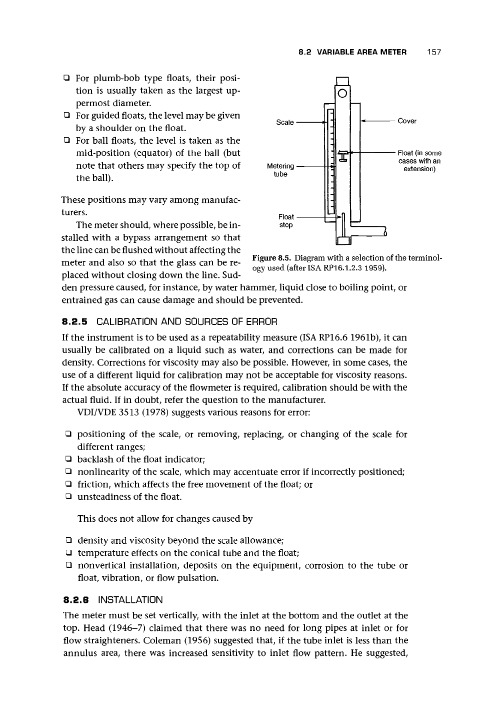
• For plumb-bob type floats, their posi-
tion is usually taken as the largest up-
permost diameter.
• For guided floats, the level may be given
by a shoulder on the float.
• For ball floats, the level is taken as the
mid-position (equator) of the ball (but
note that others may specify the top of
the ball).
These positions may vary among manufac-
turers.
The meter should, where possible, be in-
stalled with a bypass arrangement so that
the line can be flushed without affecting the
meter and also so that the glass can be re-
placed without closing down the line. Sud-
Scale •
Metering -
tube
o
- Cover
- Float (in some
cases with an
extension)
Figure 8.5. Diagram with a selection of the terminol-
ogy used (after ISA RP16.1.2.3 1959).
den pressure caused, for instance, by water hammer, liquid close to boiling point, or
entrained gas can cause damage and should be prevented.
8.2.5 CALIBRATION
AND
SOURCES
OF
ERROR
If the instrument is to be used as a repeatability measure (ISA RP16.6 1961b), it can
usually be calibrated on a liquid such as water, and corrections can be made for
density. Corrections for viscosity may also be possible. However, in some cases, the
use of a different liquid for calibration may not be acceptable for viscosity reasons.
If the absolute accuracy of the flowmeter is required, calibration should be with the
actual fluid. If in doubt, refer the question to the manufacturer.
VDI/VDE 3513 (1978) suggests various reasons for error:
• positioning of the scale, or removing, replacing, or changing of the scale for
different ranges;
• backlash of the float indicator;
• nonlinearity of the scale, which may accentuate error if incorrectly positioned;
• friction, which affects the free movement of the float; or
• unsteadiness of the float.
This does not allow for changes caused by
• density and viscosity beyond the scale allowance;
• temperature effects on the conical tube and the float;
• nonvertical installation, deposits on the equipment, corrosion to the tube or
float, vibration, or flow pulsation.
8.2.6 INSTALLATION
The meter must be set vertically, with the inlet at the bottom and the outlet at the
top.
Head (1946-7) claimed that there was no need for long pipes at inlet or for
flow straighteners. Coleman (1956) suggested that, if the tube inlet is less than the
annulus area, there was increased sensitivity to inlet flow pattern. He suggested,
158 OTHER MOMENTUM-SENSING METERS
therefore, that the maximum tube diameter should not be more than 1.41 times
the float diameter (1.414
2
= 2 so that this figure ensures that the annulus area
is less than the float cross-sectional area). Because of the entry arrangements and
the low accuracy at the bottom of the scale, one might expect that installation
would have a negligible effect. This appeared to be Head's (1946-7) view. However,
some manufacturers recommend at least 5D upstream installation length and may
suggest a downstream straight length, which may, in some cases, be greater than the
upstream length. A safe rule may be, in the absence of guidance, to take at least 5D
of straight pipe both up- and downstream. Installation is more critical with short
stroke VA meters where turbulence leads to float instability and reading problems,
but modern detector systems can partially overcome this by averaging. Installation
into a large diameter gas pipeline can result, at low flows, in vertical oscillation of
the float (bounce) often with increasing amplitude and limited only by the float
stops.
8.2.7 UNSTEADY AND PULSATING FLOWS
Dijstelbergen (1964) reported extensive mathematics and experimental work on the
behavior of the
VA
meters in a pulsating flow and claimed that "the response of the
instrument and the value of the error in the mean float position with pulsating flow
can be predicted." Chatter and bounce can be reduced with guided floats or float
rod extensions with a pneumatic damper. Nevertheless, Dijstelbergen
;
s experience
of applying these meters in pulsating flow would suggest the need for caution.
8.2.8 INDUSTRIAL TYPES, RANGES, AND PERFORMANCE
Upward flow is, of course, specified, and the meter should be mounted to minimize
strain on the glass tube.
Typical uncertainty claimed for these instruments is 1-3% of full-scale deflection
as supplied, and probably
0.5-1%
repeatability.
Ranges for liquid may be from 0.0011/min to 100 m
3
/h, and ranges for gas, from
0.1 1/min to 1,800 m
3
/h.
A
meter, typically, has a 10:1 turndown.
Meter tubes are made of glass, acrylic, and special transparent materials where
visual reading is used. There is a move to use metal to avoid breakage, etc., for safety
reasons.
Transparent tubes are now used mainly for inert liquid and gas applications.
Where a metal tube is used, sensing is usually through a magnetic link. For mag-
netic sensing, the float may be in a tapered tube, or the float may be tapered and,
with a fixed orifice, form a variable annulus. The float will probably contain a mag-
net, and the sensing head will form as closely coupled a magnetic circuit as possible
(Figure 8.3). These designs are giving way to newer field-sensing methods. The re-
mainder of the meter may be of aluminum, nylon, stainless steel, PVC, etc.
Temperature can range from -180 to 400°C for metal tubes and rather less for
others.
The manufacturer may give advice on flushing the line before the meter is in-
stalled and may recommend filters (magnetic if particles are ferromagnetic) for use
with devices using metal tubes and magnetic position sensing.
8.3 SPRING-LOADED DIAPHRAGM (VARIABLE AREA) METERS
159
IT)
O
8.2.9
COMPUTATIONAL ANALYSIS
OF
THE VARIABLE AREA FLOWMETER
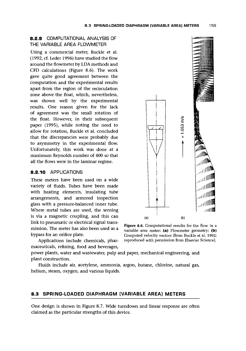
Using a commercial meter, Buckle et al.
(1992,
cf. Leder 1996) have studied the flow
around the flowmeter by LDA methods and
CFD calculations (Figure 8.6). The work
gave quite good agreement between the
computation and the experimental results
apart from the region of the recirculation
zone above the float, which, nevertheless,
was shown well by the experimental
results. One reason given for the lack
of agreement was the small rotation of
the float. However, in their subsequent
paper (1995), while noting the need to
allow for rotation, Buckle et al. concluded
that the discrepancies were probably due
to asymmetry in the experimental flow.
Unfortunately, this work was done at a
maximum Reynolds number of 400 so that
all the flows were in the laminar regime.
8.2.10
APPLICATIONS
These meters have been used on a wide
variety of fluids. Tubes have been made
with heating elements, insulating tube
arrangements, and armored inspection
glass with a pressure-balanced inner tube.
Where metal tubes are used, the sensing
is via a magnetic coupling, and this can
link to pneumatic or electrical signal trans-
mission. The meter has also been used as a
bypass for an orifice plate.
Applications include chemicals, phar-
maceuticals, refining, food and beverages,
power plants, water and wastewater, pulp and paper, mechanical engineering, and
plant construction.
Fluids include air, acetylene, ammonia, argon, butane, chlorine, natural gas,
helium, steam, oxygen, and various liquids.
.mm
(a) (b)
Figure 8.6. Computational results for the flow in a
variable area meter: (a) Flowmeter geometry; (b)
Computed velocity vectors (from Buckle et al. 1992;
reproduced with permission from Elsevier Science).
8.3 SPRING-LOADED DIAPHRAGM (VARIABLE AREA) METERS
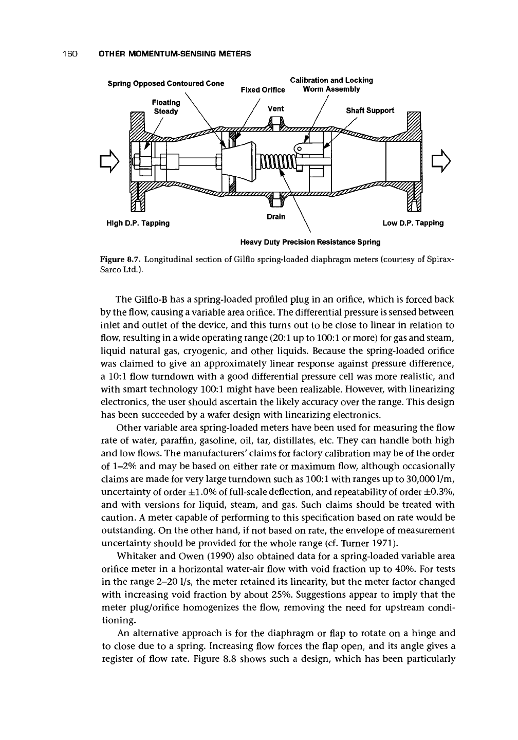
One design is shown in Figure 8.7. Wide turndown and linear response are often
claimed as the particular strengths of this device.
160
OTHER MOMENTUM-SENSING METERS
Spring Opposed Contoured Cone Calibration and Locking
Fixed Orifice Worm Assembly
High D.P. Tapping
Low D.P. Tapping
Heavy Duty Precision Resistance Spring
Figure 8.7. Longitudinal section of Gilflo spring-loaded diaphragm meters (courtesy of Spirax-
Sarco Ltd.).
The Gilflo-B has a spring-loaded profiled plug in an orifice, which is forced back
by the flow, causing
a
variable area orifice. The differential pressure is sensed between
inlet and outlet of the device, and this turns out to be close to linear in relation to
flow, resulting in
a
wide operating range
(20:1
up to 100:1 or more) for gas and steam,
liquid natural gas, cryogenic, and other liquids. Because the spring-loaded orifice
was claimed to give an approximately linear response against pressure difference,
a 10:1 flow turndown with a good differential pressure cell was more realistic, and
with smart technology 100:1 might have been realizable. However, with linearizing
electronics, the user should ascertain the likely accuracy over the range. This design
has been succeeded by a wafer design with linearizing electronics.
Other variable area spring-loaded meters have been used for measuring the flow
rate of water, paraffin, gasoline, oil, tar, distillates, etc. They can handle both high
and low flows. The manufacturers' claims for factory calibration may be of the order
of 1-2% and may be based on either rate or maximum flow, although occasionally
claims are made for very large turndown such as 100:1 with ranges up to 30,0001/m,
uncertainty of order ±1.0% of full-scale deflection, and repeatability of order
±0.3%,
and with versions for liquid, steam, and gas. Such claims should be treated with
caution.
A
meter capable of performing to this specification based on rate would be
outstanding. On the other hand, if not based on rate, the envelope of measurement
uncertainty should be provided for the whole range (cf. Turner 1971).
Whitaker and Owen (1990) also obtained data for a spring-loaded variable area
orifice meter in a horizontal water-air flow with void fraction up to 40%. For tests
in the range 2-20 1/s, the meter retained its linearity, but the meter factor changed
with increasing void fraction by about 25%. Suggestions appear to imply that the
meter plug/orifice homogenizes the flow, removing the need for upstream condi-
tioning.
An alternative approach is for the diaphragm or flap to rotate on a hinge and
to close due to a spring. Increasing flow forces the flap open, and its angle gives a
register of flow rate. Figure 8.8 shows such a design, which has been particularly
8.3 SPRING-LOADED DIAPHRAGM (VARIABLE AREA) METERS 161
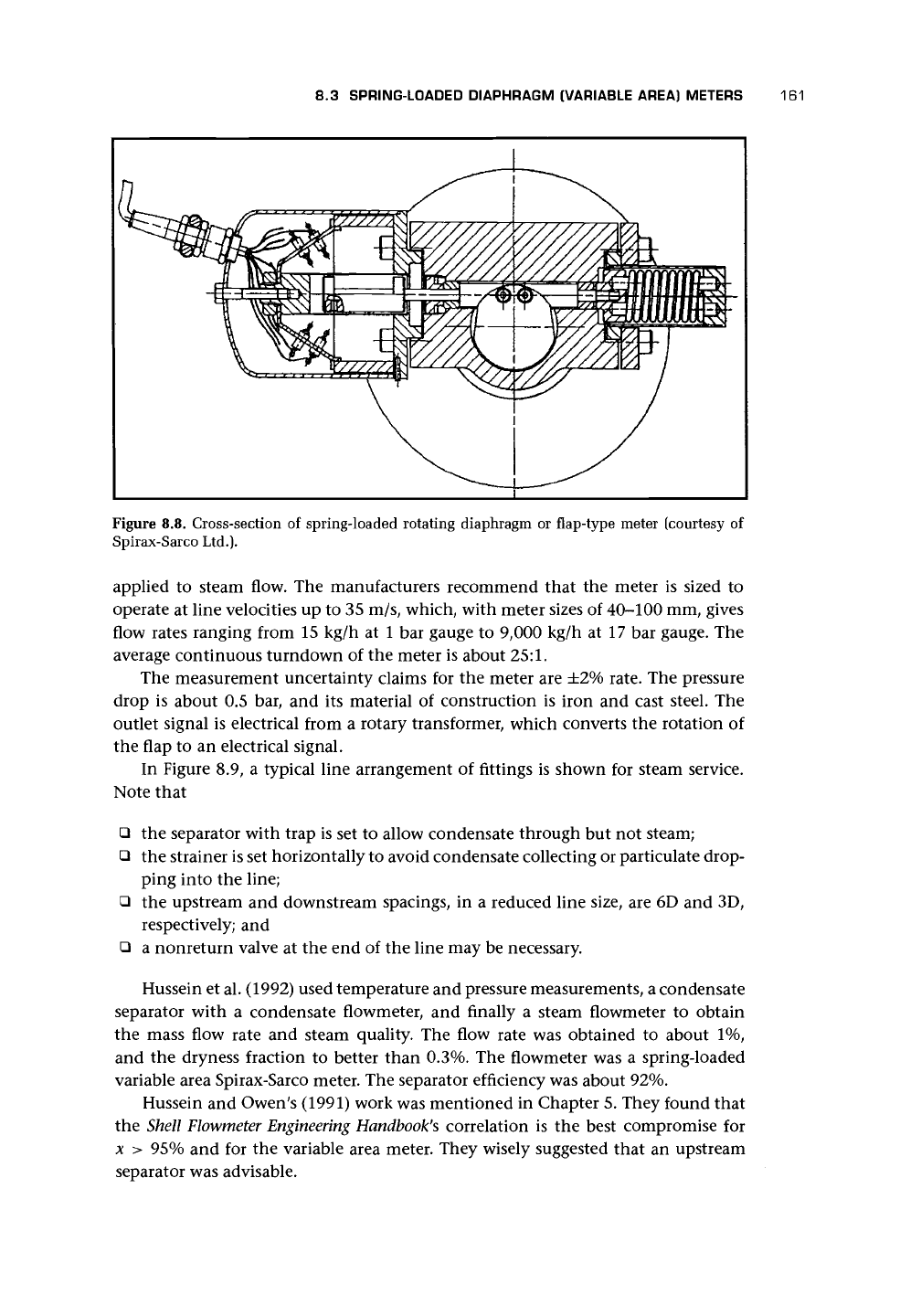
Figure 8.8. Cross-section of spring-loaded rotating diaphragm or flap-type meter (courtesy of
Spirax-Sarco Ltd.).
applied to steam flow. The manufacturers recommend that the meter is sized to
operate at line velocities up to 35 m/s, which, with meter sizes of 40-100 mm, gives
flow rates ranging from 15 kg/h at 1 bar gauge to 9,000 kg/h at 17 bar gauge. The
average continuous turndown of the meter is about 25:1.
The measurement uncertainty claims for the meter are ±2% rate. The pressure
drop is about 0.5 bar, and its material of construction is iron and cast steel. The
outlet signal is electrical from a rotary transformer, which converts the rotation of
the flap to an electrical signal.
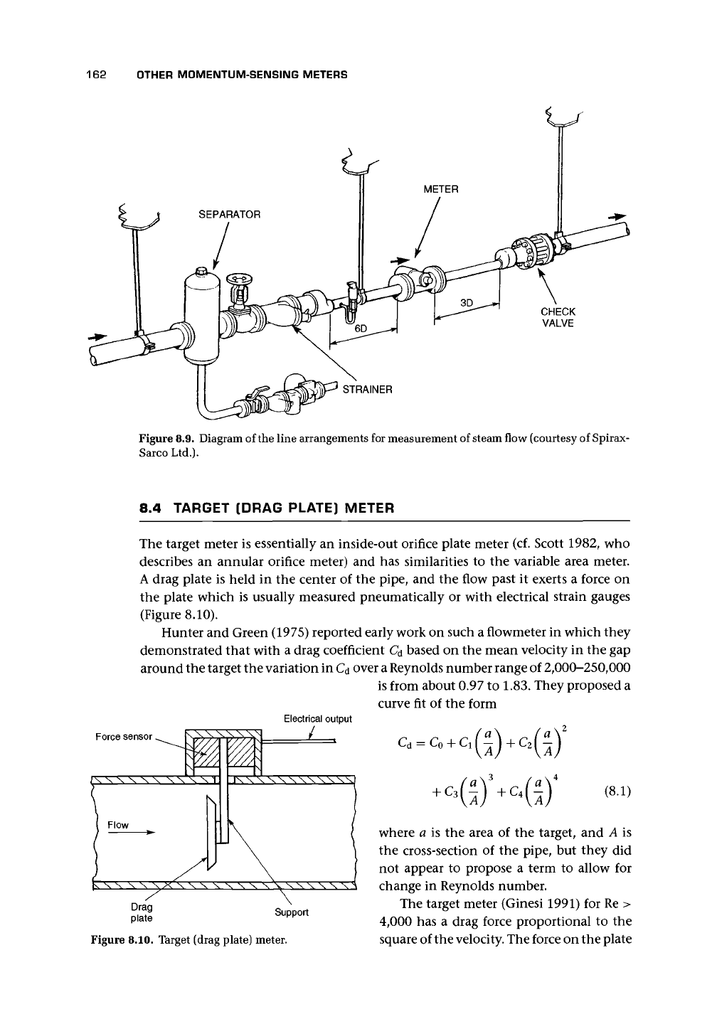
In Figure 8.9, a typical line arrangement of fittings is shown for steam service.
Note that
• the separator with trap is set to allow condensate through but not steam;
• the strainer is set horizontally to avoid condensate collecting or particulate drop-
ping into the line;
• the upstream and downstream spacings, in a reduced line size, are 6D and 3D,
respectively; and
• a nonreturn valve at the end of the line may be necessary.
Hussein et al. (1992) used temperature and pressure measurements, a condensate
separator with a condensate flowmeter, and finally a steam flowmeter to obtain
the mass flow rate and steam quality. The flow rate was obtained to about 1%,
and the dryness fraction to better than 0.3%. The flowmeter was a spring-loaded
variable area Spirax-Sarco meter. The separator efficiency was about 92%.
Hussein and Owen's (1991) work was mentioned in Chapter 5. They found that
the Shell
Flowmeter Engineering Handbook's
correlation is the best compromise for
x > 95% and for the variable area meter. They wisely suggested that an upstream
separator was advisable.
162 OTHER MOMENTUM-SENSING METERS
CHECK
VALVE
STRAINER
Figure 8.9. Diagram of the line arrangements for measurement of steam flow (courtesy of Spirax-
Sarco Ltd.).
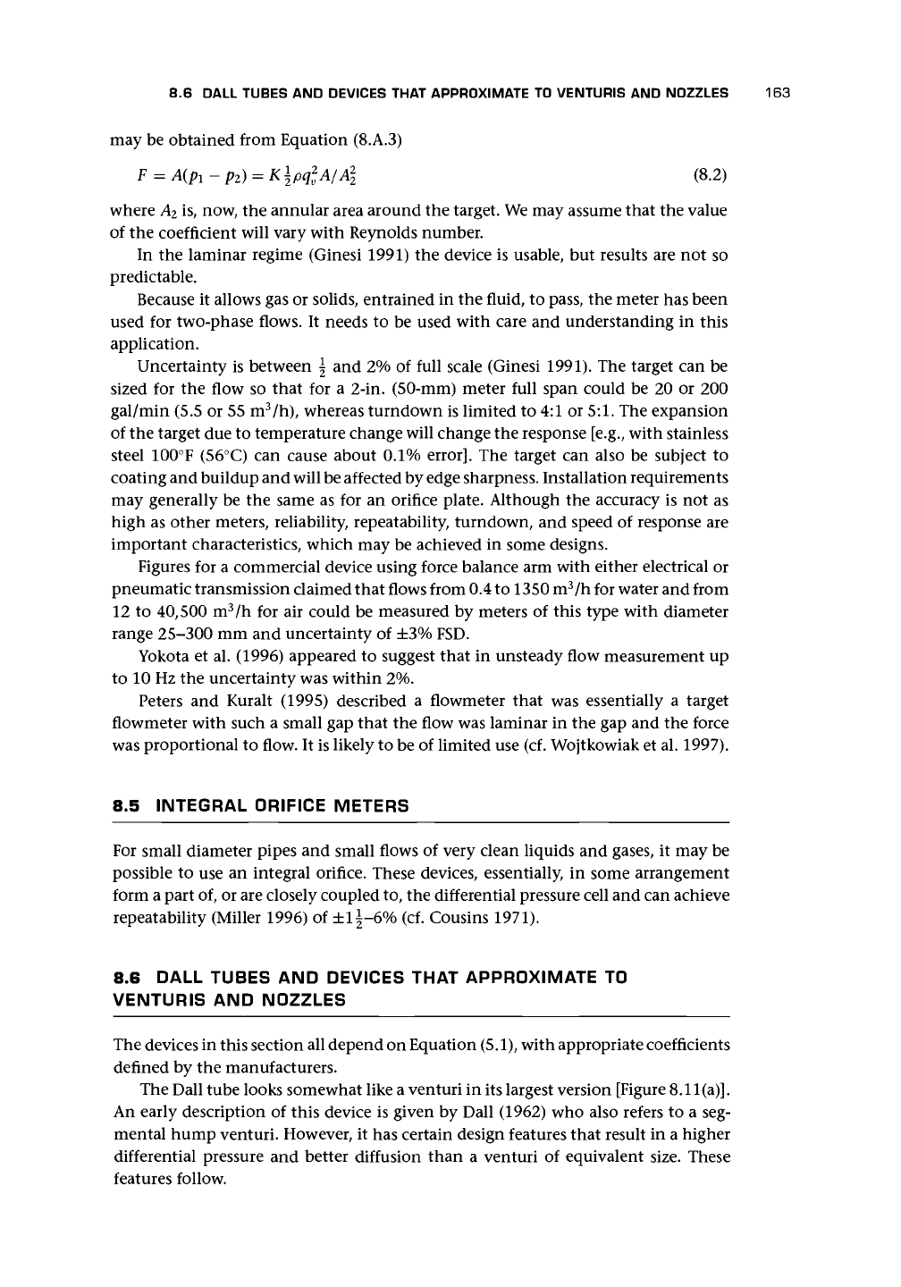
8.4 TARGET (DRAG PLATE) METER
The target meter is essentially an inside-out orifice plate meter (cf. Scott 1982, who
describes an annular orifice meter) and has similarities to the variable area meter.
A drag plate is held in the center of the pipe, and the flow past it exerts a force on
the plate which is usually measured pneumatically or with electrical strain gauges
(Figure 8.10).
Hunter and Green (1975) reported early work on such a flowmeter in which they
demonstrated that with a drag coefficient C
d
based on the mean velocity in the gap
around the target the variation in C
d
over
a
Reynolds number range of 2,000-250,000
is from about 0.97 to 1.83. They proposed a
curve fit of the form
Electrical output
Force sensor ^ —-^-——*-~
/ X X X X X X X X X X
1
Flow
XX\\XXXX
X XV X
+
c
3
-
Figure 8.10. Target (drag plate) meter.
(8.1)
where a is the area of the target, and A is
the cross-section of the pipe, but they did
not appear to propose a term to allow for
change in Reynolds number.
The target meter (Ginesi 1991) for Re >
4,000 has a drag force proportional to the
square of the
velocity.
The force on the plate
8.6 DALL TUBES AND DEVICES THAT APPROXIMATE TO VENTURIS AND NOZZLES 163
may be obtained from Equation (8.A.3)
F
= A(
Pl
-p
2
) = K
\pq
2
v
A/A\
(8.2)
where A
2
is, now, the annular area around the target. We may assume that the value
of the coefficient will vary with Reynolds number.
In the laminar regime (Ginesi 1991) the device is usable, but results are not so
predictable.
Because it allows gas or solids, entrained in the fluid, to pass, the meter has been
used for two-phase flows. It needs to be used with care and understanding in this
application.
Uncertainty is between \ and 2% of full scale (Ginesi 1991). The target can be
sized for the flow so that for a 2-in. (50-mm) meter full span could be 20 or 200
gal/min (5.5 or 55 m
3
/h), whereas turndown is limited to 4:1 or
5:1.
The expansion
of the target due to temperature change will change the response [e.g., with stainless
steel 100°F (56°C) can cause about 0.1%
error].
The target can also be subject to
coating and buildup and will be affected by edge sharpness. Installation requirements
may generally be the same as for an orifice plate. Although the accuracy is not as
high as other meters, reliability, repeatability, turndown, and speed of response are
important characteristics, which may be achieved in some designs.
Figures for a commercial device using force balance arm with either electrical or
pneumatic transmission claimed that flows from 0.4 to 1350 m
3
/h for water and from
12 to 40,500 m
3
/h for air could be measured by meters of this type with diameter
range 25-300 mm and uncertainty of ±3% FSD.
Yokota et al. (1996) appeared to suggest that in unsteady flow measurement up
to 10 Hz the uncertainty was within 2%.
Peters and Kuralt (1995) described a flowmeter that was essentially a target
flowmeter with such a small gap that the flow was laminar in the gap and the force
was proportional to flow. It is likely to be of limited use (cf. Wojtkowiak et al. 1997).
8.5 INTEGRAL ORIFICE METERS
For small diameter pipes and small flows of very clean liquids and gases, it may be
possible to use an integral orifice. These devices, essentially, in some arrangement
form a part of, or are closely coupled to, the differential pressure cell and can achieve
repeatability (Miller 1996) of ±l\-6% (cf. Cousins 1971).
8.6 DALL TUBES AND DEVICES THAT APPROXIMATE TO
VENTURIS AND NOZZLES
The devices in this section all depend on Equation (5.1), with appropriate coefficients
defined by the manufacturers.
The Dall tube looks somewhat like a venturi in its largest version [Figure 8.11
(a)].
An early description of this device is given by Dall (1962) who also refers to a seg-
mental hump venturi. However, it has certain design features that result in a higher
differential pressure and better diffusion than a venturi of equivalent size. These
features follow.
164
OTHER MOMENTUM-SENSING METERS
PRESSURE TAPPINGS
(a)
PRESSURE TAPPING-THROAT
x// /////// /
V
////////////
PRESSURE TAPPING-INLET
(b)
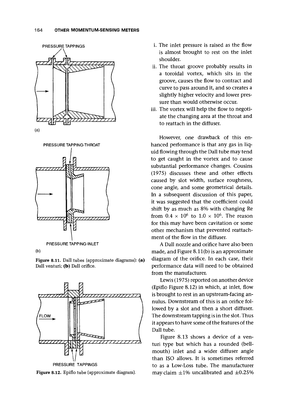
Figure 8.11. Dall tubes (approximate diagrams): (a)
Dall venturi; (b) Dall orifice.
f FLOW
r/////////
.
1\
y
V//////////////7
m—
PRESSURE TAPPINGS
Figure 8.12. Epiflo tube (approximate diagram).
i. The inlet pressure is raised as the flow
is almost brought to rest on the inlet
shoulder.
ii.
The throat groove probably results in
a toroidal vortex, which sits in the
groove, causes the flow to contract and
curve to pass around it, and so creates a
slightly higher velocity and lower pres-
sure than would otherwise occur.
iii.
The vortex will help the flow to negoti-
ate the changing area at the throat and
to reattach in the diffuser.
However, one drawback of this en-
hanced performance is that any gas in liq-
uid flowing through the Dall tube may tend
to get caught in the vortex and to cause
substantial performance changes. Cousins
(1975) discusses these and other effects
caused by slot width, surface roughness,
cone angle, and some geometrical details.
In a subsequent discussion of this paper,
it was suggested that the coefficient could
shift by as much as 8% with changing Re
from 0.4 x 10
6
to 1.0 x 10
6
. The reason
for this may have been cavitation or some
other mechanism that prevented reattach-
ment of the flow in the diffuser.
A
Dall nozzle and orifice have also been
made, and Figure 8.11(b) is an approximate
diagram of the orifice. In each case, their
performance data will need to be obtained
from the manufacturer.
Lewis (1975) reported on another device
(Epiflo Figure 8.12) in which, at inlet, flow
is brought to rest in an upstream-facing an-
nulus.
Downstream of this is an orifice fol-
lowed by a slot and then a short diffuser.
The downstream tapping
is
in the slot. Thus
it appears to have some of the features of the
Dall tube.
Figure 8.13 shows a device of a ven-
turi type but which has a rounded (bell-
mouth) inlet and a wider diffuser angle
than ISO allows. It is sometimes referred
to as a Low-Loss tube. The manufacturer
may claim ±1% uncalibrated and ±0.25%
8.7 WEDGE AND V-CONE DESIGNS 165
calibrated with a repeatability of
±0.1%
and
a turndown of
10:1.
Sizes range from 13 to
1,200 mm. Installation is claimed to require
12D upstream and 2D downstream for all
but partially shut valves and elbows in dif-
ferent planes.
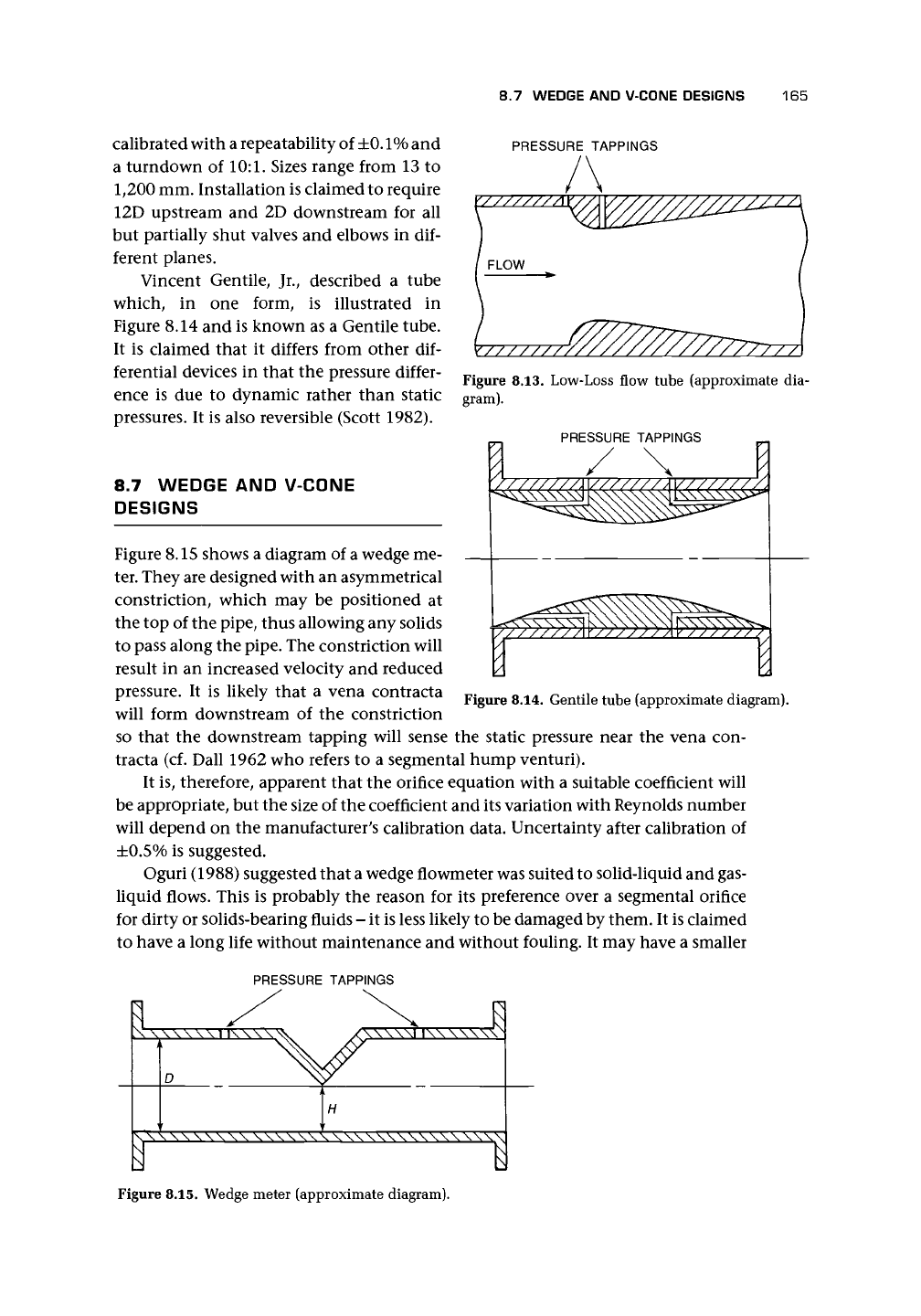
Vincent Gentile, Jr., described a tube
which, in one form, is illustrated in
Figure 8.14 and is known as a Gentile tube.
It is claimed that it differs from other dif-
ferential devices in that the pressure differ-
ence is due to dynamic rather than static
pressures. It is also reversible (Scott 1982).
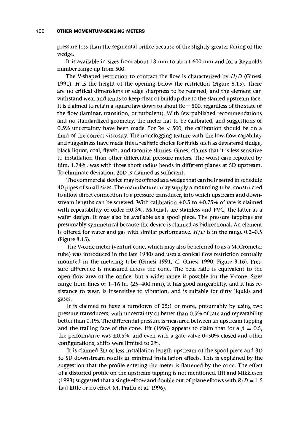
8.7 WEDGE AND V-CONE
DESIGNS
Figure 8.15 shows a diagram of a wedge me-
ter. They are designed with an asymmetrical
constriction, which may be positioned at
the top of the pipe, thus allowing any solids
to pass along the pipe. The constriction will
result in an increased velocity and reduced
pressure. It is likely that a vena contracta
will form downstream of the constriction
PRESSURE TAPPINGS
Figure 8.13. Low-Loss flow tube (approximate dia-
gram).
PRESSURE TAPPINGS
1
Figure 8.14. Gentile tube (approximate diagram).
so that the downstream tapping will sense the static pressure near the vena con-
tracta (cf. Dall 1962 who refers to a segmental hump venturi).
It is, therefore, apparent that the orifice equation with a suitable coefficient will
be appropriate, but the size of the coefficient and its variation with Reynolds number
will depend on the manufacturer's calibration data. Uncertainty after calibration of
±0.5%
is suggested.
Oguri (1988) suggested that a wedge flowmeter was suited to solid-liquid and gas-
liquid flows. This is probably the reason for its preference over a segmental orifice
for dirty or solids-bearing fluids - it is less likely to be damaged by them. It is claimed
to have a long life without maintenance and without fouling. It may have a smaller
PRESSURE TAPPINGS
Figure 8.15. Wedge meter (approximate diagram).
166 OTHER MOMENTUM-SENSING METERS
pressure loss than the segmental orifice because of the slightly greater fairing of the
wedge.
It is available in sizes from about 13 mm to about 600 mm and for a Reynolds
number range up from 500.
The V-shaped restriction to contract the flow is characterized by H/D (Ginesi
1991).
H is the height of the opening below the restriction (Figure 8.15). There
are no critical dimensions or edge sharpness to be retained, and the element can
withstand wear and tends to keep clear of buildup due to the slanted upstream face.
It is claimed to retain a square law down to about Re = 500, regardless of the state of
the flow (laminar, transition, or turbulent). With few published recommendations
and no standardized geometry, the meter has to be calibrated, and suggestions of
0.5%
uncertainty have been made. For Re < 500, the calibration should be on a
fluid of the correct viscosity. The nonclogging feature with the low-flow capability
and ruggedness have made this a realistic choice for fluids such as dewatered sludge,
black liquor, coal, flyash, and taconite slurries. Ginesi claims that it is less sensitive
to installation than other differential pressure meters. The worst case reported by
him,
1.74%,
was with three short radius bends in different planes at 5D upstream.
To eliminate deviation, 20D is claimed as sufficient.
The commercial device may be offered as
a
wedge that can be inserted in schedule
40 pipes of small sizes. The manufacturer may supply a mounting tube, constructed
to allow direct connection to a pressure transducer, into which upstream and down-
stream lengths can be screwed. With calibration ±0.5 to ±0.75% of rate is claimed
with repeatability of order ±0.2%. Materials are stainless and PVC, the latter as a
wafer design. It may also be available as a spool piece. The pressure tappings are
presumably symmetrical because the device is claimed as bidirectional. An element
is offered for water and gas with similar performance. H/D is in the range 0.2-0.5
(Figure 8.15).
The V-cone meter (venturi cone, which may also be referred to as a McCrometer
tube) was introduced in the late 1980s and uses a conical flow restriction centrally
mounted in the metering tube (Ginesi 1991, cf. Ginesi 1990; Figure 8.16). Pres-
sure difference is measured across the cone. The beta ratio is equivalent to the
open flow area of the orifice, but a wider range is possible for the V-cone. Sizes
range from lines of 1-16 in. (25-400 mm), it has good rangeability, and it has re-
sistance to wear, is insensitive to vibration, and is suitable for dirty liquids and
gases.
It is claimed to have a turndown of 25:1 or more, presumably by using two
pressure transducers, with uncertainty of better than 0.5% of rate and repeatability
better than
0.1%.
The differential pressure is measured between an upstream tapping
and the trailing face of the cone. Ifft (1996) appears to claim that for a p = 0.5,
the performance was
±0.5%,
and even with a gate valve 0-50% closed and other
configurations, shifts were limited to 2%.
It is claimed 3D or less installation length upstream of the spool piece and 3D
to 5D downstream results in minimal installation effects. This is explained by the
suggestion that the profile entering the meter is flattened by the cone. The effect
of a distorted profile on the upstream tapping is not mentioned. Ifft and Mikklesen
(1993) suggested that a single elbow and double out-of-plane elbows with R/D =1.5
had little or no effect (cf. Prahu et al. 1996).