Baker R.C. Flow Measurement Handbook: Industrial Designs, Operating Principles, Performance, and Applications
Подождите немного. Документ загружается.

8.A.1 SOME HISTORY 177
will continue to have a place. Several of the designs described have been introduced
relatively recently.
If a manufacturer is considering the introduction of new designs, the user will
be dependent on manufacturer's data for most of the designs that fall outside a stan-
dard's specification. The quality of the manufacturer's total operation will, therefore,
be a key consideration. The effect of installation should be plausible compared with
similar devices from elsewhere. The biggest uncertainty will be in the special condi-
tions that are unforeseen: small traces of gas in a liquid becoming trapped in flow
vortices, deposition of small quantities of a solid or liquid film, and materials prob-
lems.
Increasingly, however, the question will need to be asked, "Is there a linear
meter that would be more appropriate?"
APPENDIX
8.A
History, Equations, and Accuracy Classes
for the VA Meter
8.A.1 SOME HISTORY
In 1873, G. F. Deacon produced a design that resembled a variable area meter. This
was very similar to an earlier device patented in 1868 and made by
E.
A. Chamberoy
of Paris (Coleman 1956). Something similar was devised by Sir J. Alfred Ewing
(1924-5) in about 1876 and was initially known as the Ewing flowmeter. Further
experiments were carried out by Awbery and Griffiths (1926-7). They found that
the float, if a ball, started chattering at high flows and caused an overreading. Three
solutions were suggested:
i. Inclining the tube so that the ball rolled on the wall. This was Ewing's preferred
solution,
ii.
Using a float of a different shape. Awbery and Griffiths (1926-7) mentioned that
the meter used a cylindrical float with helical channels to cause slow rotation,
iii.
Stretching a fine wire along the tube close to the wall, to prevent the chattering
motion (Advisory Committee on Aeronautics 1916-17). Awbery and Griffiths
verified this in their observations.
One possible reason for this instability (Leder 1996) is a saddle point (free stag-
nation point) that forms in the wake downstream of the ball and off-axis and that
rotates and induces a large scale rotating helical vortex together with small scale
turbulence motions.
Ewing suggested that the range of the instrument could be extended by incor-
porating more than one float. The largest would be on top and would record low
flows,
and the smaller ones underneath would rise when the flow rate was sufficient.
Ewing also used a dye trace to show the nature of the flow. An alternative could be
to have two floats of similar size but with the top one of lower density.
178 OTHER MOMENTUM-SENSING METERS
Awbery and Griffiths showed that their experimental results collapsed onto
a
single curve for
a
given diameter ratio
of
D/d, where D is the diameter
of
the tube
at a certain height, and d is the diameter of the ball. They plotted log[q
v
D/(D
2
—
d
2
)]
against \og[d
3
(pf
—
p)/v
2
p], where
q
v
is
the volumetric flow rate,
p is the
density
of the fluid,
pt is the
density
of
the float,
and v is the
kinematic viscosity
of
the
fluid.
British Patent 2428 granted to
G.
Joslin of Colchester (1879) covered a device for
ascertaining rate
of
consumption of gas, which resembles
a
VA
meter, and this was
followed
in
1908 by
a
patent granted
to
K. Kuppers
of
Aachen for
a
tube and float
very similar to
Joslin's.
Felix Meyer of Aachen obtained the patent and started man-
ufacturing the tubes.
In
1921 Trost Brothers Ltd. of England took up Meyer's agency
for the United Kingdom, and in 1931 Schutte and Koerting secured the manufactur-
ing rights for the United States. Coleman (1956) gave a very useful historical review
from which some of these notes are taken.
Head (1946) refers
to a
downdraught instrument
in
which
the
float
is
lighter
than the fluid.
8.A.2 EQUATIONS
The basic theory
of
the flowmeter depends
on
the upthrust
on
the float resulting
from the pressure loss across
it
where
pi
and p
2
are the upstream and downstream pressures,
K
is a loss coefficient,
p
is the density and V is the velocity in the annular passage past the float. Replacing
velocity by volumetric flow rate q
v
such that
V =
q
y
/A
2
(8.A.2)
where A
2
is the annular area around the float, we obtain
Pi-p
2
=
K
1
1
pq
2
/A
2
(8.A.3)
This equation assumes that the dynamic head
at
inlet
is
negligible, and that
the
pressure difference across the float is caused by the loss of the dynamic head down-
stream of the float. Dijstelbergen (1964) uses a contraction coefficient C
c
for the ratio
Ml
A
x
,
where
A
x
is the area of the tapering tube at height
x.
The immersed weight of the float is given by
W=V
f
(
Pi
-p)g
(8.A.4)
where V
f
is the volume of the float, p
f
is the density of the material of the float,
and
g is the acceleration due to gravity. Thus, the balance is given by
- p)g (8.A.5)
where A
f
is the maximum cross-sectional area of the float.
8.A.2 EQUATIONS
179
This is usually rewritten as
C
c
2V
f
(pt-p)g
(8.A.6)
with l/y/K replaced by
C
(e.g., Martin 1949,
Coleman 1956; cf. Head 1946-7).
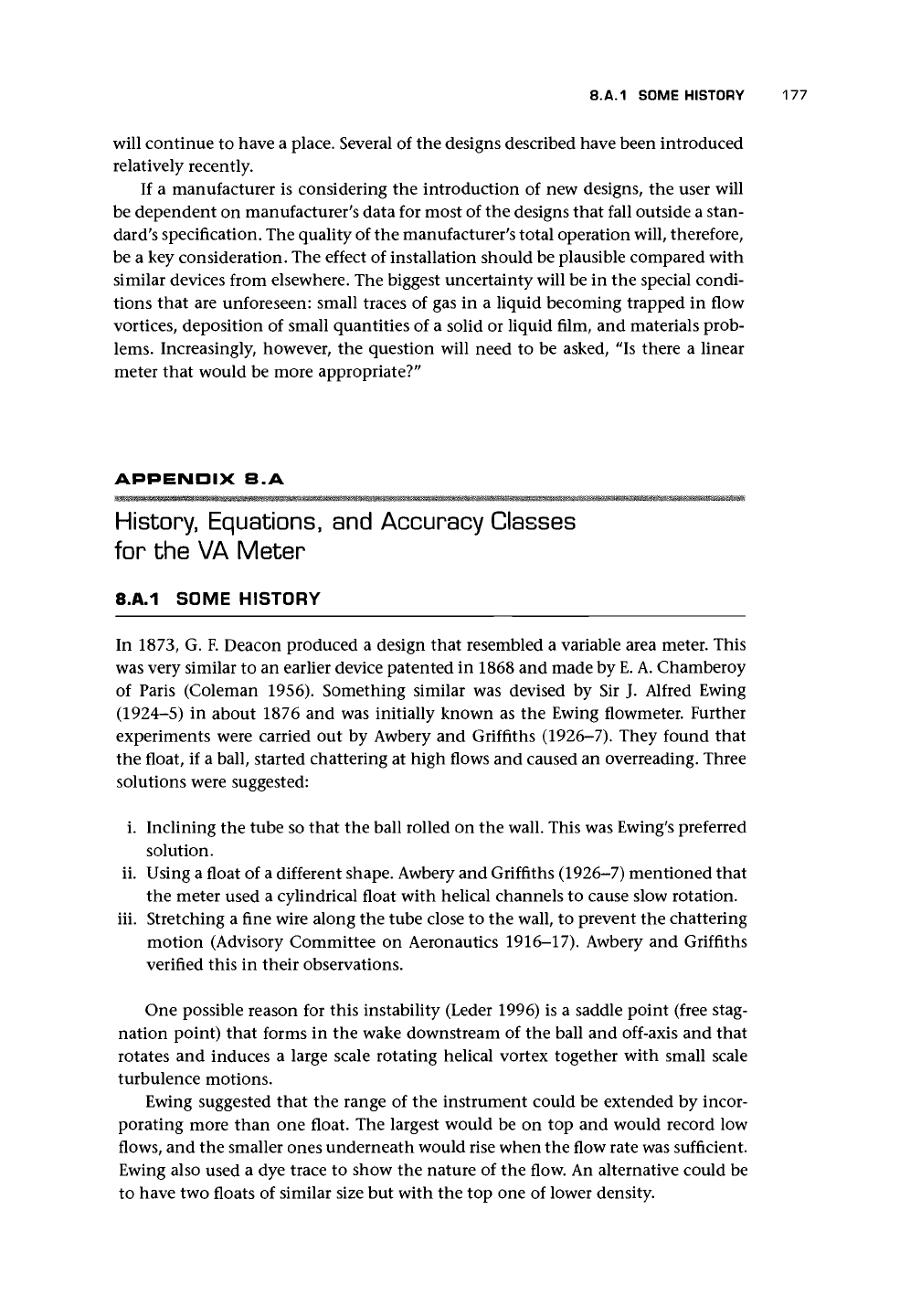
Coleman (1956) gave values of C for
three float shapes (Figure 8.A.I), which sug-
gested that at full flow the value of
C
ranged
from 0.6 for a float of low Re sensitivity
to about unity. The plots also showed a
decrease in C at low flow rates, and this
would broadly reflect the fact that the loss
coefficient for an orifice increases with re-
duced Re (Miller 1990). Coleman also plot-
ted the effect of viscosity on the various
float shapes and confirmed the implications
of Figure 8.A.I, that the plumb-bob is the
most viscosity dependent.
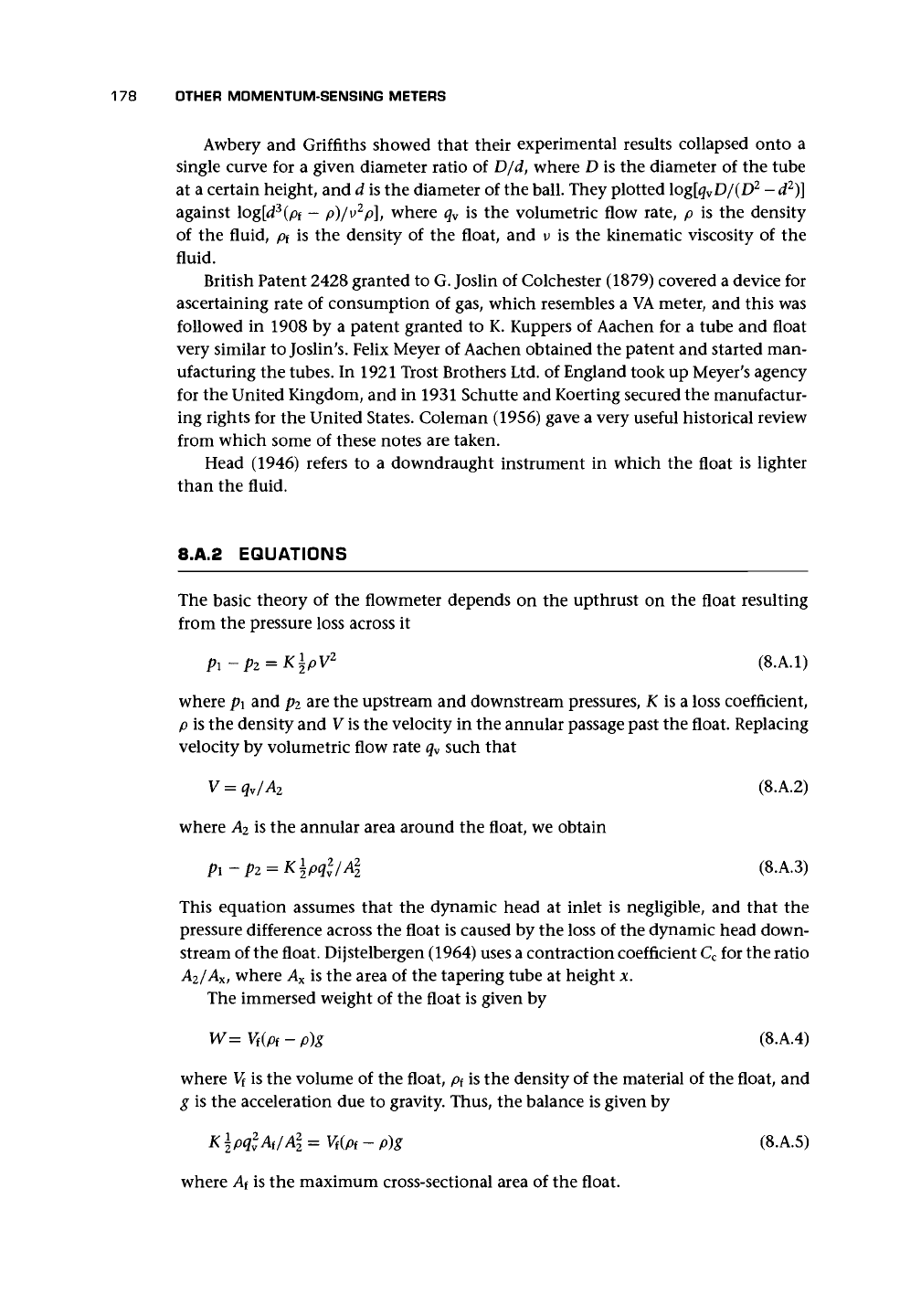
Schoenborn and Colburn (1939) gave a
curve of C against Re/C, where Re is the
Reynolds number based on D
eq
. They called
it the equivalent diameter but defined it
as the difference between D and d. This
curve is reproduced in Figure 8.A.2. It was
obtained for a large high pressure design
using a steel tube with extension rod ob-
servable through a graduated glass window.
This curve could be used as a first approxi-
mation if no other is available. They used a
balance of forces of the weight of the float in
liquid to the upward force due to the pres-
sure reduction across the float to provide
the basis for their experimental correlation.
They also noted that the curve for large
meters appeared to be less fluid-dependent
than for smaller instruments.
Although it may be difficult to predict
flow rates, it is possible to convert from
one fluid to another at the same read-
ing. Schoenborn and Colburn (1939) gave
an equation similar to that given by ISA
(1961b):
(8.A.7)
1.0
0.5
10
10
2
10°
10
4
Re
10
5
1.0
0.5
10
10
4
Re 10
5
1.0
0.5
10
10°
10
4
Re 10
5
Figure 8.A.I. Effect of float shape on flow coefficient
(after Coleman 1956).
1.0
0.5
10
Re/C 10
Figure 8.A.2. Plot of C against Re/C for
a
typical vari-
able area meter (after Schoenborn and Colburn 1939).
180
OTHER MOMENTUM-SENSING METERS
I.UO
1.02
1.01
1.00
0.99
0.98
0P7
/(P
f
-P
2
)p2
-\(P,-PI>PI
-—-^^^
—^^^
float
s.g.
7.9^/^
^^^^^—^^^ 1.44
SPECIFIC
GRAVITY
OF
METERED
FLUID
i i i
0.68
0.69 0.70
0.71
0.72 0.73 0.74 0.75 0.76
s.g. FOR
CALIBRATION
FLUID
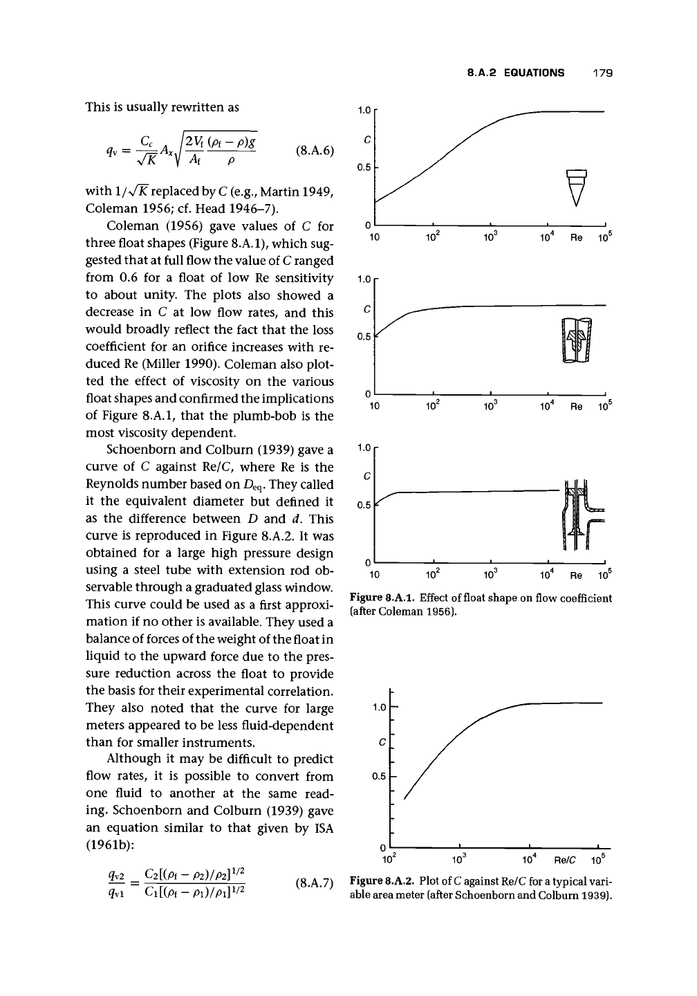
Figure 8.A.3. Density compensation float comparison curves (after Coleman
1956).
The difference is that ISA (1961b) omits
C2/C1,
thereby making the assumption
that the ratio is unity. Coleman (1956) also used this equation with C2/C1 equal
to unity, noting that variation of viscosity is ignored. He referred to the fact that if
Equation (8.A.6) is rewritten for mass flow rate and differentiated for variation in
fluid density, it can be shown that a float density, of twice the fluid density gives a
zero change and, therefore, is least sensitive to variation in density (cf. Head 1946).
Figure 8.A.3 shows values of the density correction factor with change of fluid density
and for various float densities, based on calibration for aviation gasoline of specific
gravity
0.72.
Head (1946) also raised the possibility that, with a downdraught design,
the requirement from differentiating the volume flow equation of a float of zero
density could be achieved approximately. Head also suggested that float automatic
compensation might be used to allow for temperature variation and other variables.
Several authors have pointed out that the value of C is constant if /x/y/pipf
—
p) is
constant.
8.A.3 ACCURACY CLASSES
To define the accuracy of the variable area flowmeter, VDI/VDE 3513 (1978) recom-
mended an accuracy class and divided the reading into two parts:
• First part is three-quarters of the actual flow rate M;
• Second part is one-quarter of full-scale or upper range value E.
The summation error F in flow rate, in actual flow rate units, is then given by
8.A.3 ACCURACY CLASSES 181
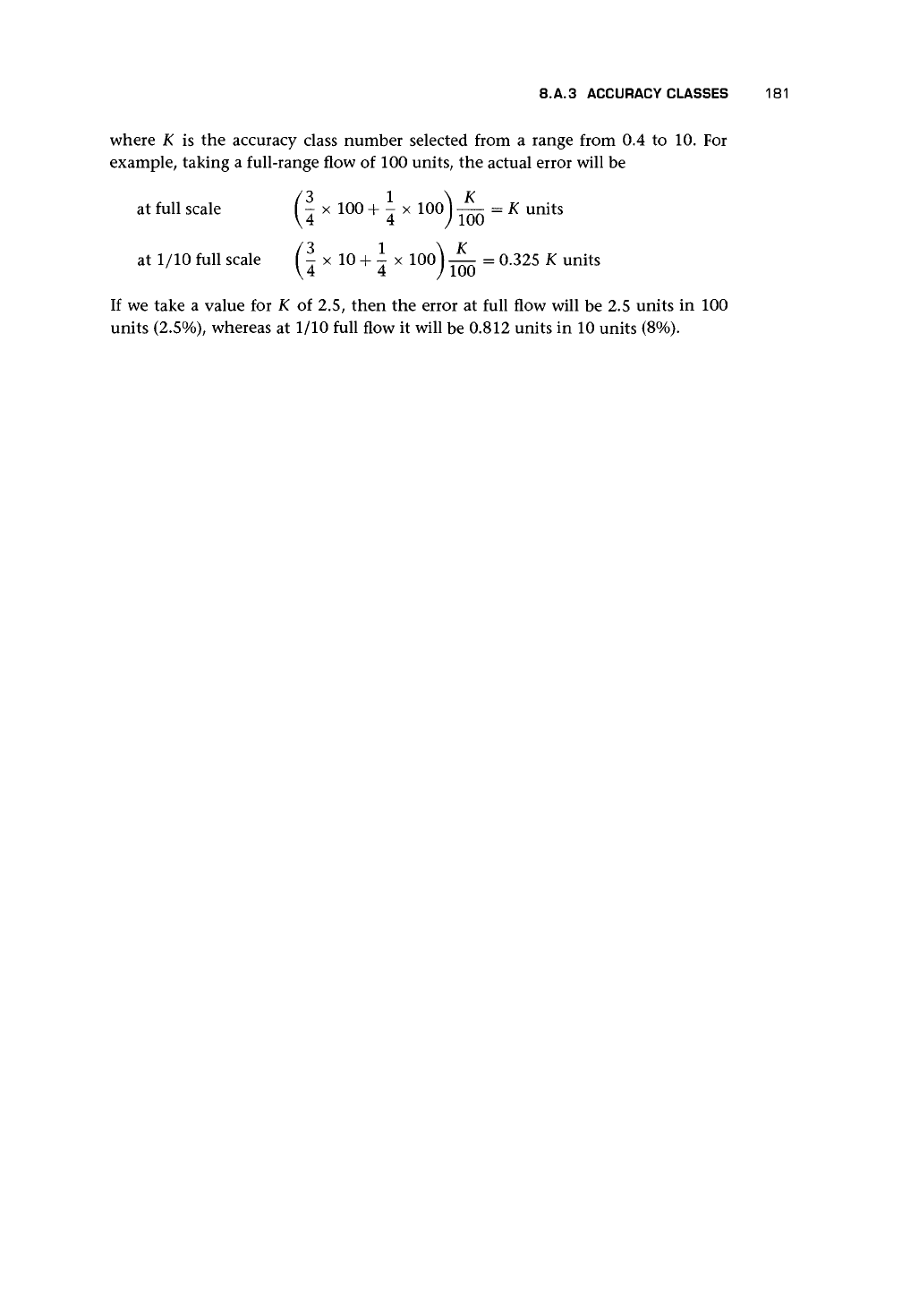
where K is the accuracy class number selected from a range from 0.4 to 10. For
example, taking a full-range flow of 100 units, the actual error will be
at full scale f | x 100 + i x 100^ -^- = K units
at 1/10 full scale (- x 10 + - x lOo) — = 0.325 K units
\4 4 J 100
If we take a value for K of 2.5, then the error at full flow will be 2.5 units in 100
units (2.5%), whereas at 1/10 full flow it will be 0.812 units in 10 units (8%).
CHAPTER
S
Positive Displacement Flowmeters
9.1 INTRODUCTION
The material in this chapter is based on the paper by Baker and Morris (1985) on
positive displacement (PD) meters, which in turn has been updated with more re-
cent industrial and published material and extended to gases. P.D. Baker's (1983)
paper provided some additional useful information on these meters. The main types
of liquid meter were given by Barnes (1982), Hendrix (1982), Henke (1955), and
Gerrard (1979) (cf. Mankin 1955). The reader should refer to API (1992) and similar
documents.
At least four of the meter designs to be discussed have been around for over 100
years.
The nutating disk flowmeter for liquids was developed in 1850. The rotary
piston meter appeared in the late nineteenth century (Baker 1998).
The measurement of gas has depended, from an early date, on two types of
positive displacement meter: the wet gas meter of high accuracy and credited to
Samuel Clegg (1815), and the diaphragm meter of lower performance but greater
range for which William Richards (1843) should take the credit.
9.1.1 BACKGROUND
The concept of carrying known volumes of fluid through a flowmeter is a short step
from the use of a discrete measure such as a bucket or measuring flask. Thus in each
of the designs described later, the flow enters a compartment that is as tightly sealed
as is compatible with relative movement of adjacent components. A knowledge of
how many of these compartments move through the flowmeter in one rotation of
the shaft leads to a knowledge of the flow rate for a certain rotational speed. A sim-
ple theory is developed in Appendix 9.A.I. Clearly every leakage path will reduce
or increase the amount carried and cause an uncertainty in the measurement. We
can make an approximation of the leakage flows in the simple model. In addition,
pressure and temperature will distort the volume and may cause small errors, and
we may need to develop compensation for these. Compensation for pressure can
be provided in the form of a double-walled meter in which the precision-measuring
chamber is unpressurized since the pressure is the same inside and out, and the pres-
sure drop to the outside world is taken across the second and outer wall, the shape of
which will not affect the accuracy. The temperature compensation, if necessary, can
be incorporated into the calibration adjustment by a temperature-sensitive element.
Very often these devices provide a direct sales ticket that is produced by the
rotation of the meter and the starting and stopping of the flow. On the other hand,
182
9.1 INTRODUCTION 183
it is very difficult to make small adjustments as needed in calibration where the
signal is from a mechanical rotation. We, therefore, need to introduce complicated
mechanical calibrators where a frequency output is not acceptable. The combination
of mechanical counter and ticket machine can cause a substantial drag on the meter
and may cause slippage errors in certain types of calibrators.
Many of the points made in this chapter relate primarily to liquid measurement,
have some relevance to gases, and should be noted by those mainly interested in gas
measurement.
9.1.2 QUALITATIVE DESCRIPTION OF OPERATION
The essential of any positive displacement meter, as indicated earlier, is that a discrete
and well-defined portion of the fluid is carried from inlet to outlet without loss or
mixing with the remainder of the fluid. This applies to all the fluid that passes
through the meter. The skill and ingenuity of the designer is shown, therefore, in
achieving this as simply and precisely as possible. If, for instance, we know the
volume of each compartment of a reciprocating pump, then knowing how many
cylinder-full portions are transmitted in a revolution, we can relate the amount
passed to the speed or revolutions of the pump. This is essentially the principle
of a metering pump. Taking this a step farther, we could reverse the reciprocating
pump. Instead of providing power externally to drive the pump, the fluid moves the
pistons, and the valves ensure that each portion is transmitted, without loss, to the
outlet. Of course there will be some loss due to imperfect sealing between the pistons
and the cylinders, but provided this can be kept very small, we have the basis of a
very accurate instrument. The reciprocating principle may not be satisfactory for
high throughput meters, and so other designs have been devised. It will be easiest
to explain the working of each in turn with respect to diagrams.
The theory of the device is worked out in Appendix 9.A.I. Here we need only
note that the simplest equation of flow through such a device is
q
v
= Volume per revolution x Rotational speed
—
Leakage (9.1)
Leakage is unlikely to be a constant value for one revolution and is more likely to
be speed-dependent. The output from all meters is a rotating shaft, and this needs to
be related to the flow rate and total passed. If the shaft passes through the pressure
containment of the meter, then a rotary-shaft-sealing arrangement will be needed.
In one type of meter, an externally lubricated packing gland is used to isolate the
dynamic shaft seal from the product (Baker 1983), thereby increasing the life of the
packing gland. The external lubricant must, of course, be chemically compatible
with the product being metered. In some cases, the problem is avoided by using a
magnetic drive coupling.
In the past, calibration and transmission methods have tended to be by mecha-
nical linkage. Such a linkage loads the rotor and may alter the characteristic of the
meter. It is also difficult to design a mechanical system to adjust the calibration of
the meter. Some ingenious methods have been adopted and will be described later in
the chapter, largely for historical interest and for those who have dealings with such
devices that remain in service. Today the possibility of using electrical or optical
184
POSITIVE DISPLACEMENT FLOWMETERS
Inlet
Outlet
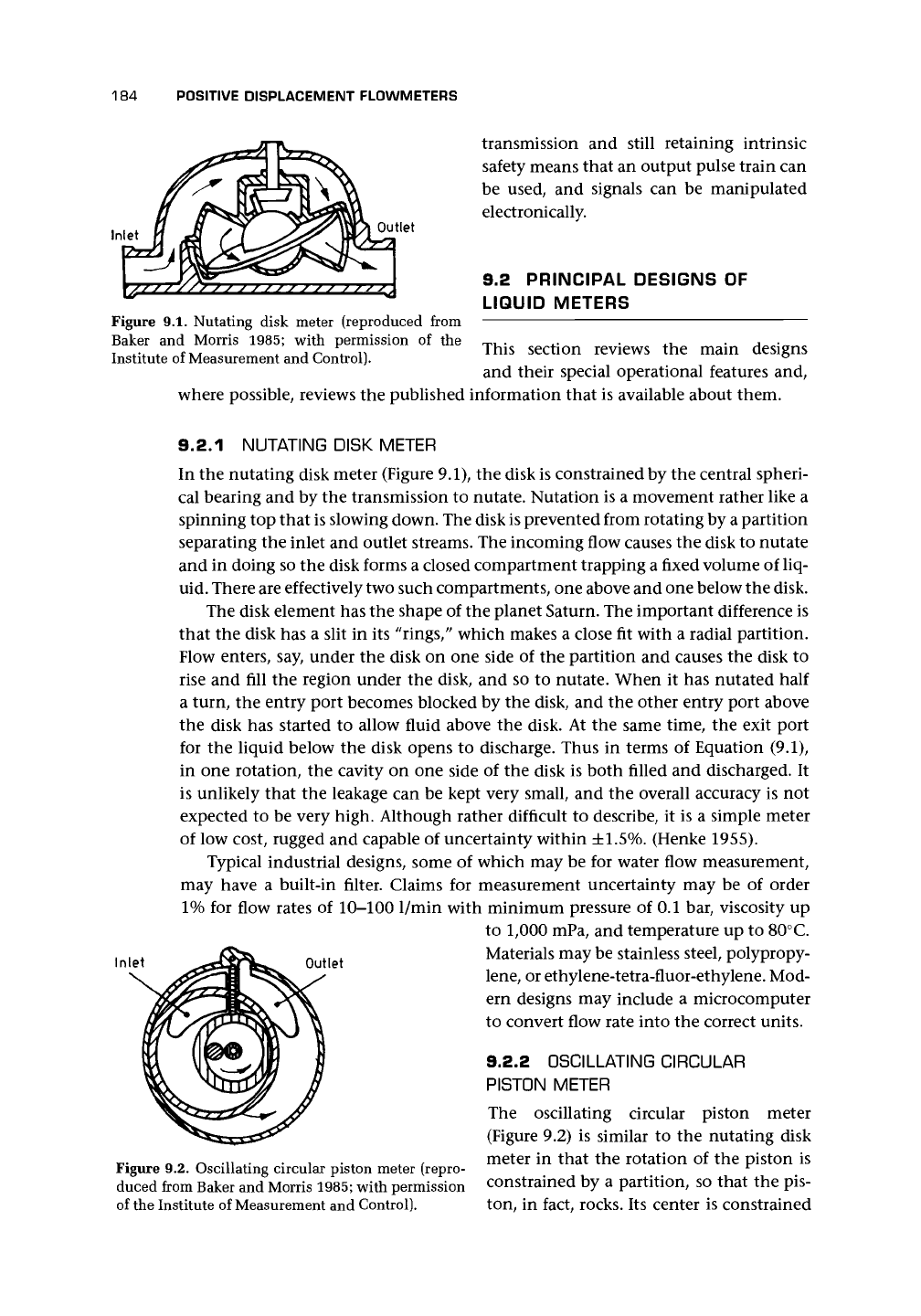
Figure 9.1. Nutating disk meter (reproduced from
Baker and Morris 1985; with permission of the
Institute of Measurement and Control).
transmission and still retaining intrinsic
safety means that an output pulse train can
be used, and signals can be manipulated
electronically.
9.2 PRINCIPAL DESIGNS OF
LIQUID METERS
This section reviews the main designs
and their special operational features and,
where possible, reviews the published information that is available about them.
Inlet
9.2.1 NUTATING DISK METER
In the nutating disk meter (Figure 9.1), the disk is constrained by the central spheri-
cal bearing and by the transmission to nutate. Nutation is a movement rather like a
spinning top that is slowing down. The disk
is
prevented from rotating by a partition
separating the inlet and outlet streams. The incoming flow causes the disk to nutate
and in doing so the disk forms a closed compartment trapping a fixed volume of liq-
uid. There are effectively two such compartments, one above and one below the disk.
The disk element has the shape of the planet Saturn. The important difference is
that the disk has a slit in its "rings/' which makes a close fit with a radial partition.
Flow enters, say, under the disk on one side of the partition and causes the disk to
rise and fill the region under the disk, and so to nutate. When it has nutated half
a turn, the entry port becomes blocked by the disk, and the other entry port above
the disk has started to allow fluid above the disk. At the same time, the exit port
for the liquid below the disk opens to discharge. Thus in terms of Equation (9.1),
in one rotation, the cavity on one side of the disk is both filled and discharged. It
is unlikely that the leakage can be kept very small, and the overall accuracy is not
expected to be very high. Although rather difficult to describe, it is a simple meter
of low cost, rugged and capable of uncertainty within
±1.5%.
(Henke 1955).
Typical industrial designs, some of which may be for water flow measurement,
may have a built-in filter. Claims for measurement uncertainty may be of order
1%
for flow rates of 10-100 1/min with minimum pressure of 0.1 bar, viscosity up
to 1,000 mPa, and temperature up to 80°C.
Materials may be stainless steel, polypropy-
lene,
or ethylene-tetra-fluor-ethylene. Mod-
ern designs may include a microcomputer
to convert flow rate into the correct units.
9.2.2 OSCILLATING CIRCULAR
PISTON METER
The oscillating circular piston meter
(Figure 9.2) is similar to the nutating disk
meter in that the rotation of the piston is
constrained by a partition, so that the pis-
ton, in fact, rocks. Its center is constrained
Outlet
Figure 9.2. Oscillating circular piston meter (repro-
duced from Baker and Morris 1985; with permission
of the Institute of Measurement and Control).
9.2 PRINCIPAL DESIGNS OF LIQUID METERS 185
Fluted
Rotors
Flow
(a)
Main
Rotor
Vanes
Stationary
Block
Flow
(b)
Second
sealing
rotor
(C)
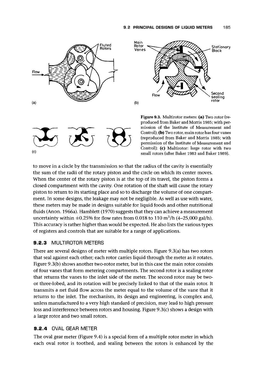
Figure 9.3. Multirotor meters: (a) Two rotor (re-
produced from Baker and Morris
1985;
with per-
mission of the Institute of Measurement and
Control); (b)
Two
rotor, main rotor has four vanes
(reproduced from Baker and Morris 1985; with
permission of the Institute of Measurement and
Control); (c) Multirotor: large rotor with two
small rotors (after Baker 1983 and Baker 1989).
to move in a circle by the transmission so that the radius of the cavity is essentially
the sum of the radii of the rotary piston and the circle on which its center moves.
When the center of the rotary piston is at the top of its travel, the piston forms a
closed compartment with the cavity. One rotation of the shaft will cause the rotary
piston to return to its starting place and so to discharge the volume of one compart-
ment. In some designs, the leakage may not be negligible. As well as use with water,
these meters may be made in designs suitable for liquid foods and other nutritional
fluids (Anon. 1966a). Hamblett (1970) suggests that they can achieve a measurement
uncertainty within ±0.25% for flow rates from 0.018 to 110 m
3
/n (4-25,000 gal/h).
This accuracy is rather higher than would be expected. He also lists the various types
of registers and controls that are suitable for a range of applications.
9.2.3 MULTIROTOR METERS
There are several designs of meter with multiple rotors. Figure 9.3(a) has two rotors
that seal against each other; each rotor carries liquid through the meter as it rotates.
Figure 9.3(b) shows another two-rotor meter, but in this case the main rotor consists
of four vanes that form metering compartments. The second rotor is a sealing rotor
that returns the vanes to the inlet side of the meter. The second rotor may be two-
or three-lobed, and its rotation will be precisely linked to that of the main rotor. It
transmits a net fluid flow across the meter equal to the volume of the vane that it
returns to the inlet. The mechanism, its design and engineering, is complex and,
unless manufactured to a very high standard of precision, may lead to high pressure
loss and interference between rotors and housing. Figure 9.3(c) shows a design with
a large rotor and two small rotors.
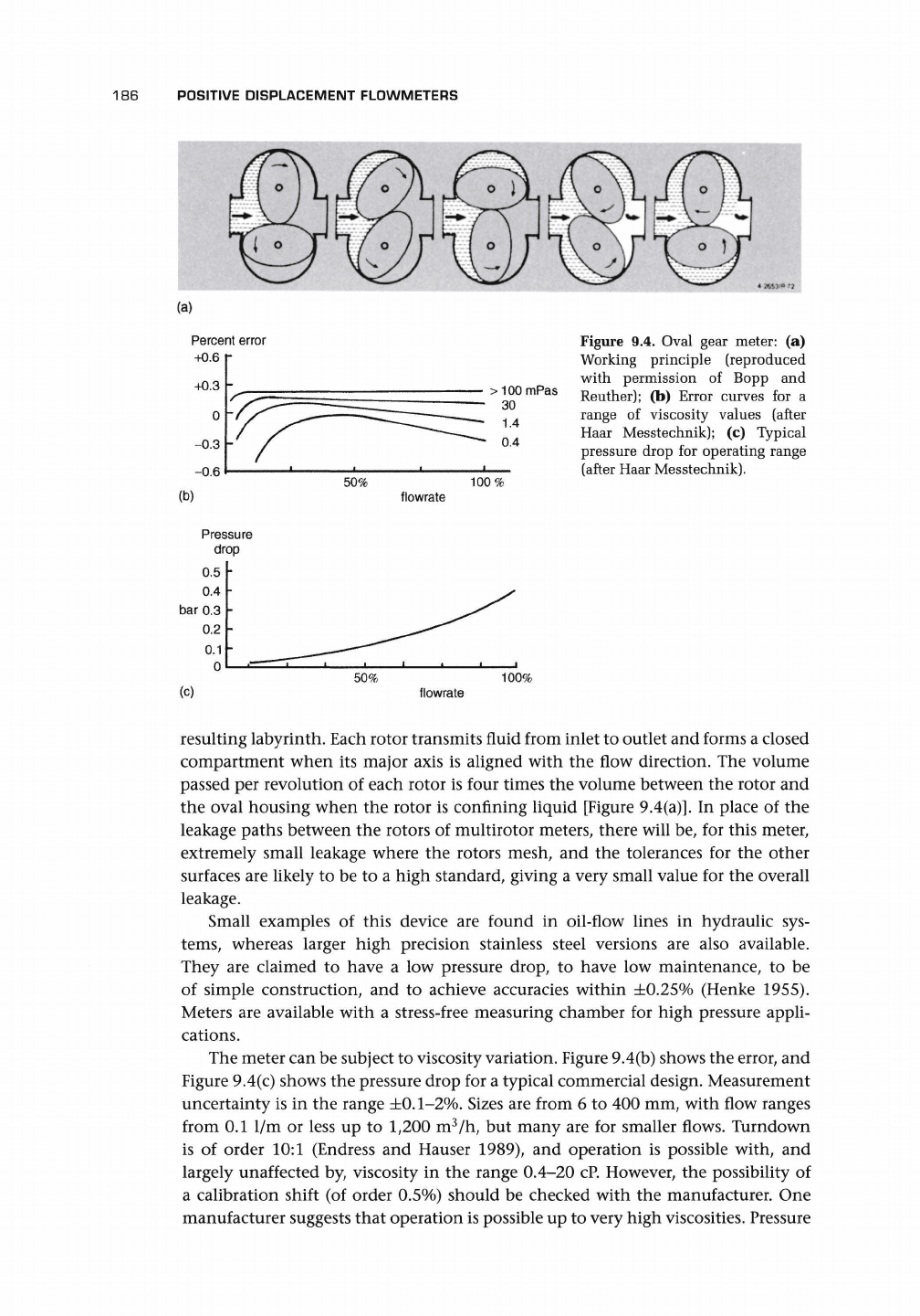
9.2.4 OVAL GEAR METER
The oval gear meter (Figure 9.4) is a special form of a multiple rotor meter in which
each oval rotor is toothed, and sealing between the rotors is enhanced by the
186
POSITIVE DISPLACEMENT FLOWMETERS
Percent error
+0.6
+0.3
0
-0.3
-0.6
(b)
Pressure
drop
0.5
0.4
bar 0.3
0,2
0.1
0
50%
100%
Figure 9.4. Oval gear meter: (a)
Working principle (reproduced
with permission of Bopp and
Reuther); (b) Error curves for a
range of viscosity values (after
Haar Messtechnik); (c) Typical
pressure drop for operating range
(after Haar Messtechnik).
flowrate
(c)
50%
100%
flowrate
resulting labyrinth. Each rotor transmits fluid from inlet to outlet and forms a closed
compartment when its major axis is aligned with the flow direction. The volume
passed per revolution of each rotor is four times the volume between the rotor and
the oval housing when the rotor is confining liquid [Figure 9.4(a)]. In place of the
leakage paths between the rotors of multirotor meters, there will be, for this meter,
extremely small leakage where the rotors mesh, and the tolerances for the other
surfaces are likely to be to a high standard, giving a very small value for the overall
leakage.
Small examples of this device are found in oil-flow lines in hydraulic sys-
tems,
whereas larger high precision stainless steel versions are also available.
They are claimed to have a low pressure drop, to have low maintenance, to be
of simple construction, and to achieve accuracies within ±0.25% (Henke 1955).
Meters are available with a stress-free measuring chamber for high pressure appli-
cations.
The meter can be subject to viscosity variation. Figure 9.4(b) shows the error, and
Figure 9.4(c) shows the pressure drop for a typical commercial design. Measurement
uncertainty is in the range ±0.1-2%. Sizes are from 6 to 400 mm, with flow ranges
from 0.1 1/m or less up to 1,200 m
3
/h, but many are for smaller flows. Turndown
is of order 10:1 (Endress and Hauser 1989), and operation is possible with, and
largely unaffected by, viscosity in the range 0.4-20 cP. However, the possibility of
a calibration shift (of order 0.5%) should be checked with the manufacturer. One
manufacturer suggests that operation is possible up to very high viscosities. Pressure