Baker R.C. Flow Measurement Handbook: Industrial Designs, Operating Principles, Performance, and Applications
Подождите немного. Документ загружается.

8.8 DIFFERENTIAL DEVICES WITH A FLOW MEASUREMENT MECHANISM IN THE BYPASS 167
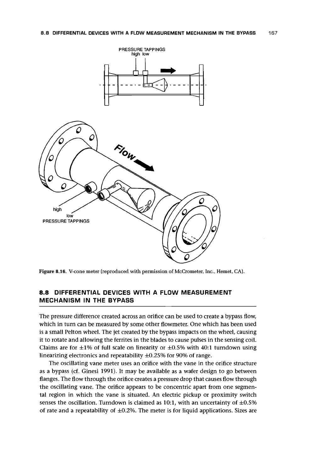
PRESSURE TAPPINGS
high low
high
low
PRESSURE TAPPINGS
Figure 8.16. V-cone meter (reproduced with permission of McCrometer, Inc., Hemet, CA).
8.8 DIFFERENTIAL DEVICES WITH A FLOW MEASUREMENT
MECHANISM IN THE BYPASS
The pressure difference created across an orifice can be used to create a bypass flow,
which in turn can be measured by some other flowmeter. One which has been used
is a small Pelton wheel. The jet created by the bypass impacts on the wheel, causing
it to rotate and allowing the ferrites in the blades to cause pulses in the sensing coil.
Claims are for ±1% of full scale on linearity or ±0.5% with 40:1 turndown using
linearizing electronics and repeatability ±0.25% for 90% of range.
The oscillating vane meter uses an orifice with the vane in the orifice structure
as a bypass (cf. Ginesi 1991). It may be available as a wafer design to go between
flanges. The flow through the orifice creates a pressure drop that causes flow through
the oscillating vane. The orifice appears to be concentric apart from one segmen-
tal region in which the vane is situated. An electric pickup or proximity switch
senses the oscillation. Turndown is claimed as 10:1, with an uncertainty of ±0.5%
of rate and a repeatability of ±0.2%. The meter is for liquid applications. Sizes are
168 OTHER MOMENTUM-SENSING METERS
from 25 to 76 mm (1-3 in.). Flow range is from 1.4 to 218 m
3
/h (5-800 gal/min)
with a temperature range of about -25 to 100°C and pressure up to 21 bar. In-
stallation recommendations are compared here with those for an orifice plate with
0 = 0.3:
Oscillating Orifice
Vane
/3 =
0.3
(Upstream/Downstream)
Single bend 10/5 10/5
Two bends in same plane 15/5 16/5
Two bends in perpendicular planes 20/5 34/5
Reducer 10/5 5/5
Control valve 30/5 —
Straightener 5/5 —
Some of the claims give cause for caution when compared with the orifice values.
Other bypass elements used with differential meters are variable area, thermal,
and fluidic (Boucher et al. 1991). By including a secondary orifice in series with the
bypass, the flow in each should be approximately proportional.
8.9 SLOTTED ORIFICE PLATE
Morrison et al. (1994a, b) suggested using an orifice that had radial slots arranged on
two rings instead of
a
single central hole. The inner ring of slots extended from about
0.1R to about 0.45R, and the outer extended from about 0.55R to about 0.9R. There
were 8 slots in the inner ring and 24 in the outer, making an effective /3 = 0.43.
They concluded from tests in a 50.8-mm line that the slotted orifice is less sensi-
tive to upstream flow conditions than a standard orifice of the same effective beta
ratio.
8.10 PIPEWORK FEATURES - INLETS
If a well-formed inlet is provided to a pipe from a stilling tank or large gas vessel,
then the pressure drop from the tank or vessel into the pipe can be used to obtain
the flow rate. Equation (6.1) is simplified since fi = 0, the flow coming from a large,
essentially still, container, and so E = 1. The coefficient is also very close to unity.
The
Shell Flowmeter Engineering Handbook
(Danen 1985) gives values for the
coef-
ficient. The volumetric flow rate will be given by
q
v
= C(7t/4)d
Z
y/2Ap/p (8.3)
where d is the throat diameter (at the downstream tapping) and may equal D, the
pipe diameter downstream; Ap is the differential pressure between inlet and throat;
and p is the density. The coefficients of discharge for various designs may be ob-
tained from the Shell
Flowmeter Engineering Handbook
(Danen 1985). For example,
8.11 PIPEWORK FEATURES - BEND OR ELBOW USED AS A METER
169
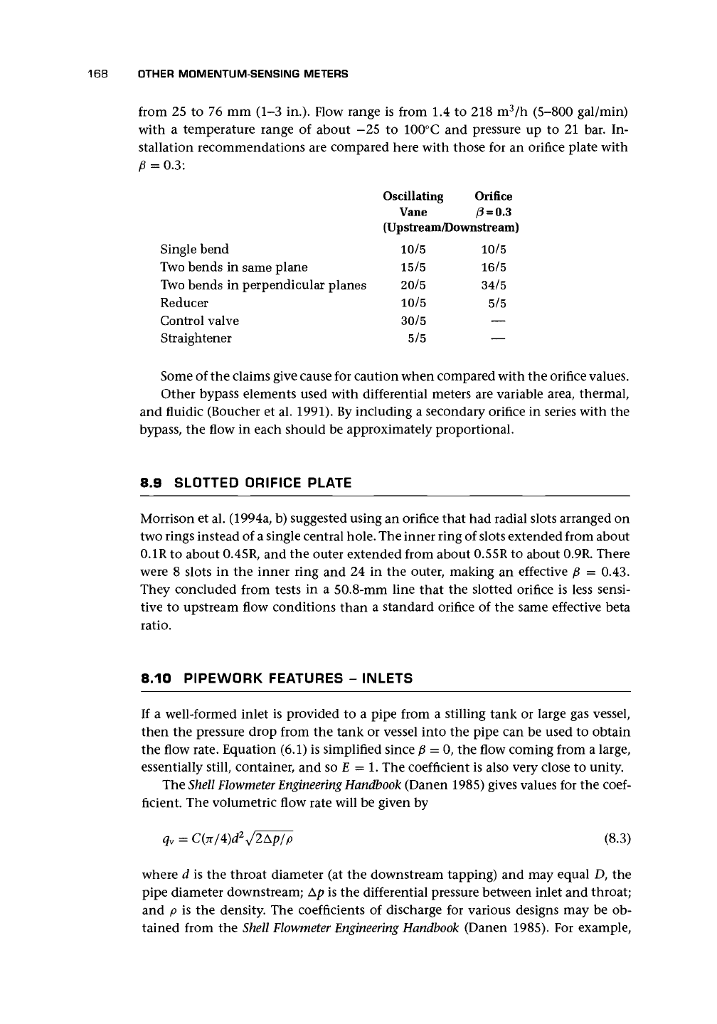
for a well-formed bell-mouth intake (cf. Fig-
ure 8.17), the values of C may be
Re number 5 x 10
3
10
4
10
5
3 x 10
5
C 0.914 0.940 0.987 0.991
The flow rate can be obtained from these
values and dimensions. The use of such an
inlet will clearly depend on the condition of
the installation and the upstream flow. The
latter should be undisturbed and have had
sufficient stilling time. Even so, the method
should be used with caution.
Ito et
al.
(1985) obtained values of about
0.95 at Re = 20,000 to nearly 0.99 at Re =
600,000, and also gave a useful list of references.
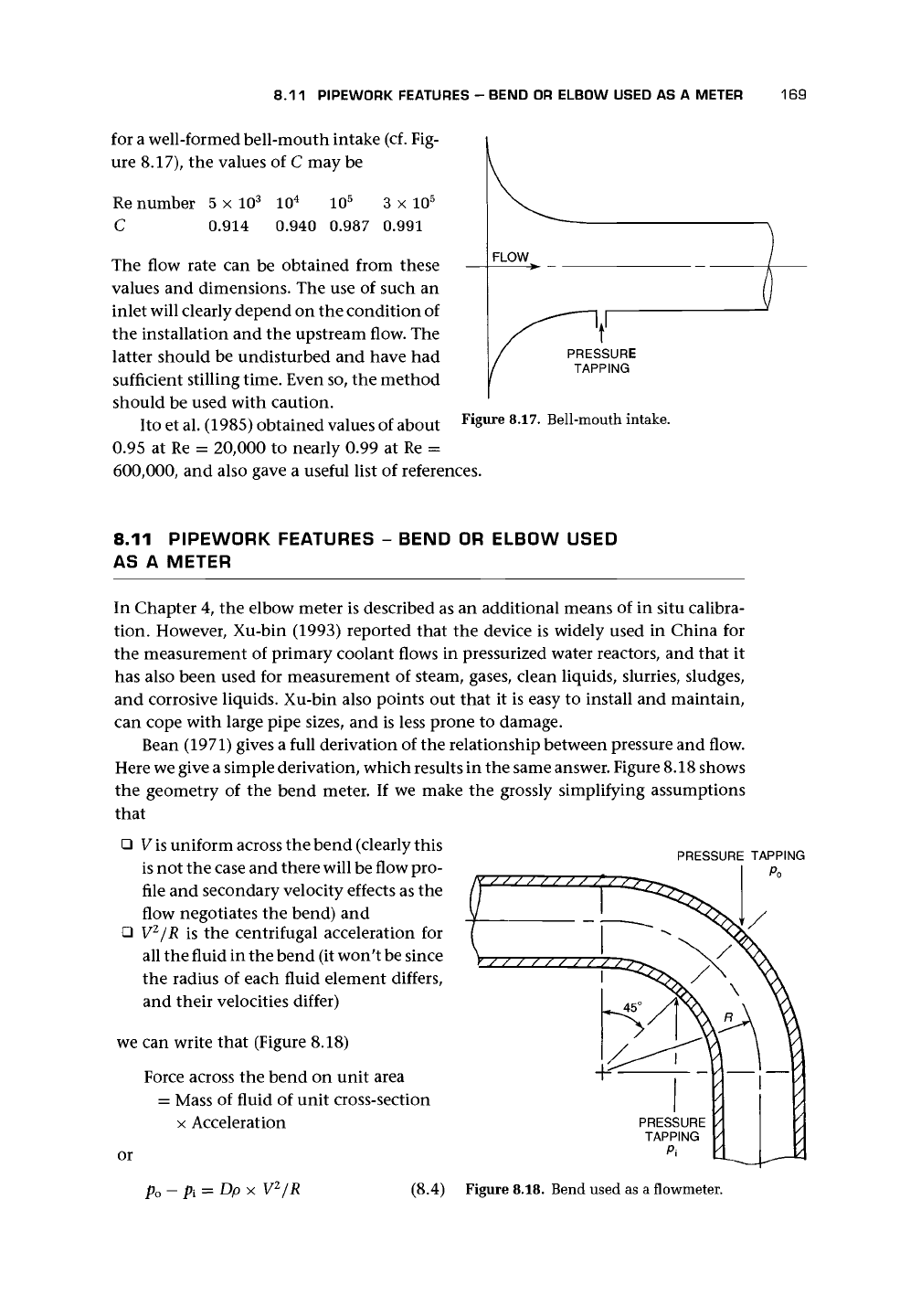
FLOW
PRESSURE
TAPPING
Figure 8.17. Bell-mouth intake.
8.11 PIPEWORK FEATURES - BEND OR ELBOW USED
AS A METER
In Chapter 4, the elbow meter is described as an additional means of in situ calibra-
tion. However, Xu-bin (1993) reported that the device is widely used in China for
the measurement of primary coolant flows in pressurized water reactors, and that it
has also been used for measurement of steam, gases, clean liquids, slurries, sludges,
and corrosive liquids. Xu-bin also points out that it is easy to install and maintain,
can cope with large pipe sizes, and is less prone to damage.
Bean (1971) gives a full derivation of the relationship between pressure and flow.
Here we give a simple derivation, which results in the same answer. Figure 8.18 shows
the geometry of the bend meter. If we make the grossly simplifying assumptions
that
• V
is
uniform across the bend (clearly this
is not the case and there will be flow pro-
file and secondary velocity effects as the
flow negotiates the bend) and
• V
2
/R is the centrifugal acceleration for
all the fluid in the bend (it won't be since
the radius of each fluid element differs,
and their velocities differ)
we can write that (Figure 8.18)
Force across the bend on unit area
= Mass of fluid of unit cross-section
x Acceleration
PRESSURE TAPPING
Po
or
V
2
/R
(8.4) Figure 8.18. Bend used as a flowmeter.
170 OTHER MOMENTUM-SENSING METERS
Thus
V=/P (8.5)
y D p
We are interested in the volumetric flow, and we introduce a flow coefficient to
allow for the approximations to real flow. We obtain
(8.6)
Bean gave the coefficient as
K = l-6.5/VRe (8.7)
for 10
4
< Re < 10
6
and R/D > 1.25 and suggested that an uncertainty of ±4%
should be allowed for. (Note that there appears to be a disagreement with Xu-bin's
equations.)
The use of pipe bends is also explained in the
Shell
Flowmeter Engineering Handbook
(Danen 1985) where the coefficient includes the
y/R/D.
y/R/D for a normal 100-mm
short radius bend schedule 40 is approximately unity (Danen 1985).
This method should be used with extreme caution because the condition of the
bend will be unknown and the uncertainty is unlikely to be as good as 4%.
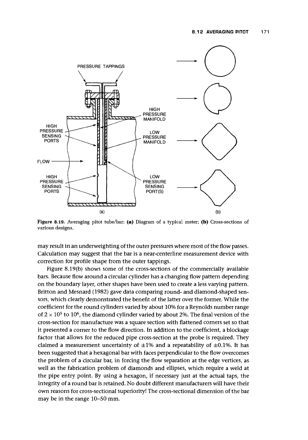
8.12 AVERAGING PITOT
The Annubar was claimed to be the first averaging pitot (Britton and Mesnard 1982),
but many others have followed. The averaging pitot
is,
strictly, neither averaging nor
pitot. In Chapter 18 we shall discuss pitot tubes, which are tubes coaxial with the
flow. Although the averaging pitot has a series of upstream-facing holes, they are un-
likely to provide a true average of the axial velocities across the pipe. The averaging
pitot consists of a bar that spans the pipe and has holes facing upstream and down-
stream [Figure 8.19(a)]. It is claimed to cope with disturbed profiles due to upstream
fittings. The flow will be brought to rest locally on the leading edge of the bar and
at the upstream holes unless interconnecting flows occur. The resulting pressures in
each of the holes, which will approach the local stagnation pressures, will be linked
by the manifold that runs inside the
bar.
The rear-facing hole or holes will experience
a pressure that approximates to the static pressure in the flow. These two pressures,
the approximate average stagnation and the approximate static, are then carried
by the internal tubes out of the bar and into a suitable pressure transducer where
the pressure difference p
u
— pa
will be calibrated against the velocity. Essentially, we
assume that this pressure difference will approximate to the dynamic pressure that
was obtained from Equation (2.10). The calculation of the actual upstream-sensed
pressure will depend on internal flows in the connecting manifold from the cen-
ter holes with higher stagnation pressure to, and possibly out of, the holes nearer
the pipe wall where the stagnation pressure will be lower. In addition, the squared
relationship
&P=\pV
2
(8.8)
8.12 AVERAGING PITOT
171
PRESSURE TAPPINGS
HIGH
PRESSURE
SENSING
PORTS
FLOW
HIGH
PRESSURE
SENSING
PORTS
LOW
PRESSURE
SENSING
PORT(S)
(b)
Figure 8.19. Averaging pitot tube/bar: (a) Diagram of a typical meter; (b) Cross-sections of
various designs.
may result in an underweighting of the outer pressures where most of the flow passes.
Calculation may suggest that the bar is a near-centerline measurement device with
correction for profile shape from the outer tappings.
Figure 8.19(b) shows some of the cross-sections of the commercially available
bars.
Because flow around a circular cylinder has a changing flow pattern depending
on the boundary layer, other shapes have been used to create a less varying pattern.
Britton and Mesnard (1982) gave data comparing round- and diamond-shaped sen-
sors,
which clearly demonstrated the benefit of the latter over the former. While the
coefficient for the round cylinders varied by about 10% for a Reynolds number range
of 2 x 10
5
to 10
6
, the diamond cylinder varied by about 2%. The final version of the
cross-section for manufacture was a square section with flattened corners set so that
it presented a corner to the flow direction. In addition to the coefficient, a blockage
factor that allows for the reduced pipe cross-section at the probe is required. They
claimed a measurement uncertainty of ±1% and a repeatability of
±0.1%.
It has
been suggested that a hexagonal bar with faces perpendicular to the flow overcomes
the problem of a circular bar, in forcing the flow separation at the edge vertices, as
well as the fabrication problem of diamonds and ellipses, which require a weld at
the pipe entry point. By using a hexagon, if necessary just at the actual taps, the
integrity of a round bar is retained. No doubt different manufacturers will have their
own reasons for cross-sectional superiority! The cross-sectional dimension of the bar
may be in the range 10-50 mm.
172 OTHER MOMENTUM-SENSING METERS
Typical performance claims for these devices are ±1% of reading with ±0.1%
repeatability for turndown of 10:1 or more and they are suitable for pipe sizes of
25 mm (1 in.) to 12 m (about 40 ft). Manufacturers should be consulted on flow
ranges. Flows of 10-30,000 m
3
/h for liquids and 200-600,000 m
3
/h for gases may
be possible. Materials are stainless steel, Monel, Hastelloy, titanium, Inconel, PVDF,
etc.
Temperature range may be from —100 to 450°C, and pressure may be up to 70
bar for some designs. It is claimed by some manufacturers that installation should
be with similar constraints to those for the orifice plate, and the connections should
also be similar to avoid condensation problems, etc. However, if we compare some
claims, we obtain the following:
Single bend
Two bends in
same plane
Two bends in
perpendicular
planes
Reducer
Expander
Valve*
0.2
Orifice,
(5
0.5 0.65
(Upstream/Downstream)
10/4
14/4
34/4
5/4
16/4
18/4
14/6
20/6
40/6
6/6
18/6
22/6
22/7
32/7
54/7
11/7
25/7
28/7
Manufacturers
A B
C (Worst
Case)
(Upstream/Downstream)
7/3
9/3
17/4
7/3
7/3
24/3
24/4
11/4
—
9/4
9/4
27/4
10/5
15/5
28/5
10/5
10/5
28/5
These results suggest that, in the absence of clear guidance from the manufac-
turer, taking the spacing for an orifice with p = 0.65 may be the wisest precaution.
It should be remembered that the accuracy of any insertion device is subject to the
uncertainty with which the pipe cross-sectional area can be measured. In the case
of averaging-pitots, there is a blockage caused by the bar, the effects of which must
be obtained from calibration.
It is not clear how manufacturers overcome the uncertainty of the pipe ID and
cross-section into which these devices are inserted. If installation of the pipe and bar
are at the same time, no doubt this measurement will be possible. The manufacturer
will then, only, need to know the allowance for blockage caused by the bar. However,
if the pipe is in position, the measurement is considerably more problematic.
In some cases, it is possible that these devices may also create vortex shedding,
a phenomenon that we shall encounter and use in the vortex-shedding flowmeter.
Unfortunately, such shedding causes lateral forces on the bar and, if these are close
to the natural frequency of the bar, may cause vibrations of an unacceptable level.
The manufacturer should be asked about this when considering such a device.
We shall discuss pitot tubes in Chapter 18 and shall find a very different shaped
device. Cutler (1982), in a letter commenting on averaging-pitots, questions whether
multihole sensors do, in fact, generate an average differential pressure. Cutler made
the important point that, for fully developed flow profiles, a single-point mea-
surement may suffice. We show in Chapter 2 that one measurement at about
* Orifice distances are based on a fully open globe valve.
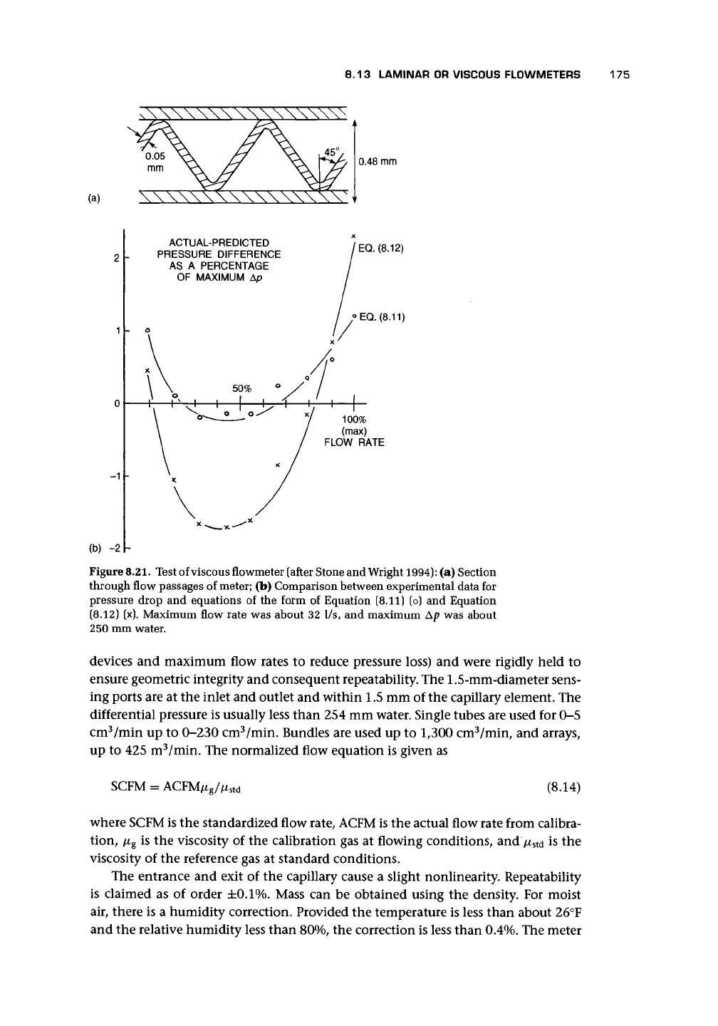
8.13 LAMINAR OR VISCOUS FLOWMETERS 173
three-quarters radius will suffice for turbulent profiles. He gives an example of a
device consisting of upstream pointing and downstream pointing tubes.
A meter of this type has been marketed as a flow/no-flow indicator. Impact
(upstream-facing) and suction (downstream-facing) ports supply a differential pres-
sure that is displayed on a gauge attached to the pipe or may be used to obtain an
indication of flow rate via differential pressure measurement.
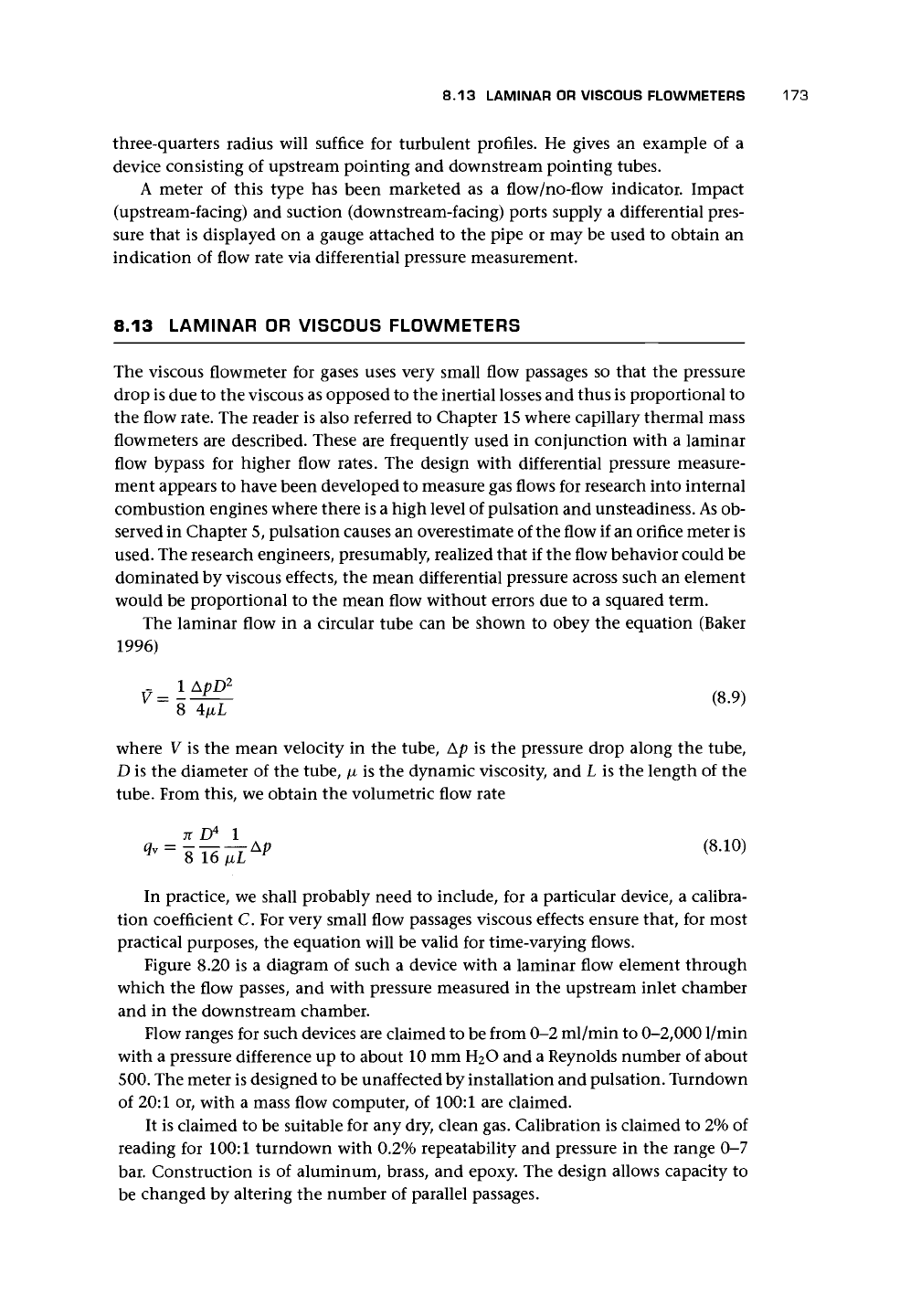
8.13 LAMINAR OR VISCOUS FLOWMETERS
The viscous flowmeter for gases uses very small flow passages so that the pressure
drop is due to the viscous as opposed to the inertial losses and thus is proportional to
the flow rate. The reader is also referred to Chapter 15 where capillary thermal mass
flowmeters are described. These are frequently used in conjunction with a laminar
flow bypass for higher flow rates. The design with differential pressure measure-
ment appears to have been developed to measure gas flows for research into internal
combustion engines where there is a high level of pulsation and unsteadiness.
As
ob-
served in Chapter 5, pulsation causes an overestimate of the flow if an orifice meter is
used. The research engineers, presumably, realized that if the flow behavior could be
dominated by viscous effects, the mean differential pressure across such an element
would be proportional to the mean flow without errors due to a squared term.
The laminar flow in a circular tube can be shown to obey the equation (Baker
1996)
1
^ (8.9)
K }
V=
8 4/xL
where V is the mean velocity in the tube, Ap is the pressure drop along the tube,
D is the diameter of the tube, /x is the dynamic viscosity, and L is the length of the
tube.
From this, we obtain the volumetric flow rate
In practice, we shall probably need to include, for a particular device, a calibra-
tion coefficient C. For very small flow passages viscous effects ensure that, for most
practical purposes, the equation will be valid for time-varying flows.
Figure 8.20 is a diagram of such a device with a laminar flow element through
which the flow passes, and with pressure measured in the upstream inlet chamber
and in the downstream chamber.
Flow ranges for such devices are claimed to be from 0-2 ml/min to 0-2,0001/min
with a pressure difference up to about 10 mm H
2
O and a Reynolds number of about
500.
The meter is designed to be unaffected by installation and pulsation. Turndown
of 20:1 or, with a mass flow computer, of 100:1 are claimed.
It is claimed to be suitable for any dry, clean gas. Calibration is claimed to 2% of
reading for 100:1 turndown with 0.2% repeatability and pressure in the range 0-7
bar. Construction is of aluminum, brass, and epoxy. The design allows capacity to
be changed by altering the number of parallel passages.
174 OTHER MOMENTUM-SENSING METERS
PRESSURE
TAPPINGS
Figure 8.20. Diagrams of a viscous flowmeter.
Weigand (1994) referred to the Hagan-Poiseuille law (Poiseuille 1842) for flow in
a capillary
Ap = Aq
v
/jLL/D
4
+ Bpql
(8.11)
where A and B are constants, L is the length of the capillary, and D is its diameter.
Other symbols have usual meaning.
Stone and Wright (1994) gave consideration to this meter and obtained the first
term in Equation (8.11) and accounted for the second term:
a. due to entry length effects, which introduced onto Equation (8.10) a factor of
(1 + QRe) where C
x
~ 0.03;
b.
due to entry and exit losses, which they estimated as being of order 0.6% of total
pressure drop;
c. due to compressibility of the gas (Fanno line cf. Baker 1996) giving an error of
about 1%.
If B is small compared with A and L/D
4
is large, Equation (8.11) becomes
Ap =
A'tiq
y
(8.12)
where A = AL/D
4
(Bean 1971). This is essentially Equation (8.10) in an alternative
form. If we include the factor in (a), we obtain
(8.13)
which is similar in form to the equation obtained by Jones (1992) except that Jones
also had a negative constant term.
Weigand claimed that the laminar flow elements that he describes can oper-
ate over turndown ratios of up to
100:1.
The main requirement is that viscosity is
known. The laminar flow element (LFE) consists of a housing and capillary element.
The housing of stainless steel or aluminum provides inlet and outlet connections,
structural support, and connections (e.g., to measure differential pressure). The cap-
illary element may consist of one capillary tube with internal diameter as small as
0.228 mm, a bundle of tubes, or a matrix array consisting of a series of triangular
passages made from 0.025-mm stainless steel stock and triangles with dimensions
of 0.58 mm or less. The length of the capillaries were 76 mm (25 mm for the largest
8.13 LAMINAR OR VISCOUS FLOWMETERS
175
AVV
(a)
XX
\\\\W\\\\V
I
0.48 mm
-1
ACTUAL-PREDICTED
PRESSURE DIFFERENCE
AS A PERCENTAGE
OF MAXIMUM Ap
EQ.
(8.12)
,°EQ.
(8.11)
100%
(max)
FLOW RATE
(b) -2h
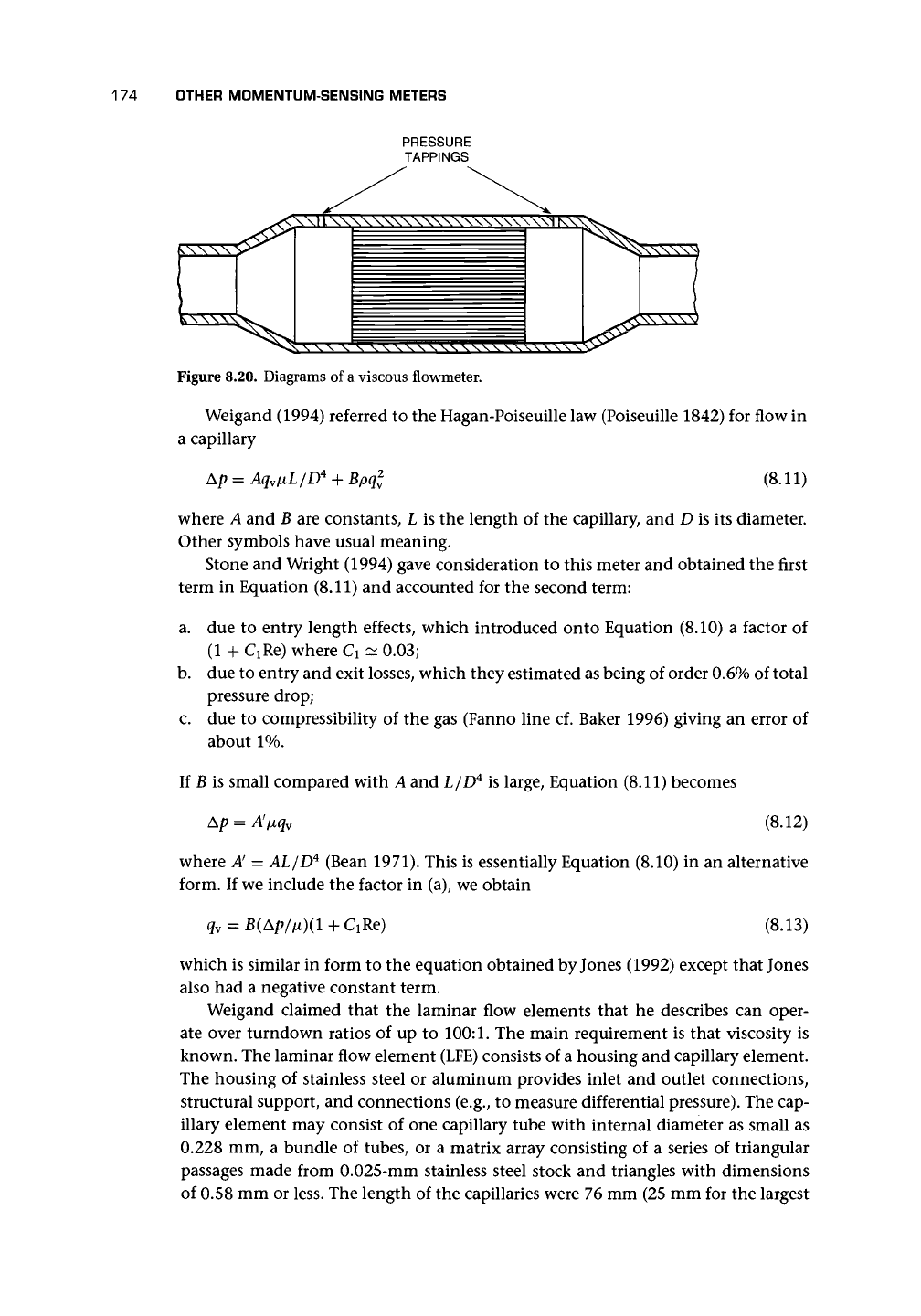
Figure
8.21.
Test of viscous flowmeter (after Stone and Wright
1994):
(a) Section
through flow passages of
meter;
(b) Comparison between experimental data for
pressure drop and equations of the form of Equation (8.11) (o) and Equation
(8.12) (x). Maximum flow rate was about 32 1/s, and maximum Ap was about
250 mm water.
devices and maximum flow rates to reduce pressure loss) and were rigidly held to
ensure geometric integrity and consequent repeatability. The 1.5-mm-diameter sens-
ing ports are at the inlet and outlet and within 1.5 mm of the capillary element. The
differential pressure is usually less than 254 mm water. Single tubes are used for 0-5
cm
3
/min up to 0-230 cm
3
/min. Bundles are used up to 1,300 cm
3
/min, and arrays,
up to 425 m
3
/min. The normalized flow equation is given as
SCFM = ACFM/x
g
//x
s
td
(8.14)
where SCFM is the standardized flow rate, ACFM is the actual flow rate from calibra-
tion, /x
g
is the viscosity of the calibration gas at flowing conditions, and >
s
td is the
viscosity of the reference gas at standard conditions.
The entrance and exit of the capillary cause a slight nonlinearity. Repeatability
is claimed as of order
±0.1%.
Mass can be obtained using the density. For moist
air, there is a humidity correction. Provided the temperature is less than about 26°F
and the relative humidity less than 80%, the correction is less than 0.4%. The meter
176 OTHER MOMENTUM-SENSING METERS
should be kept as warm as the flowing air. By combining temperature measurement,
pressure measurement, and differential pressure measurement and using a micro-
processor, gas mass flow rate is obtained. An uncertainty of
±1%
of reading for 10:1
turndown is claimed to be achievable.
Abe and Yoshinaga (1991) also described what appears to be essentially a lami-
nar flowmeter with etoile-like resistors but with the center blocked. Their slits were
recommended to be 0.2 mm wide and 40-60 mm long. With two in parallel, they
claimed flow rates up to about 0.5 x 10~
3
m
3
/s were possible, but nonlinearity ap-
peared to set in below this figure. The device may be used as a flowmeter or a means
to measure viscosity.
Stone and Wright (1994) tested a meter with passages as shown in Figure 8.21 (a)
with length 76.2 mm, about 18,000 passages and a flow area of 3507 mm
2
. The
hydraulic mean diameter
was
0.347 mm, and the mean velocity at rated flow
was
1.73
m/s.
Figure 8.21 (b) shows the flowmeter characteristic compared with a quadratic
assumption as in Equation (8.11) and a linear assumption as in Equation (8.12). Both
curves were obtained using regression analysis and not through evaluation of the
constants.
8.14 CHAPTER CONCLUSIONS
This chapter has been used to "sweep up" a number of types of meter, among which
the variable area meter is the most common. The great benefit of the transparent-
tube designs of the variable area meter is the immediate visual reassurance that flow
of a certain level is taking place. However, in many applications, a metal tube may
be considered necessary for safety reasons. Recent work has started to analyze the
flow and to identify reasons for the instability that has been observed since the first
use of the meter. There may be value in pursuing these studies further to provide an
answer to the reasons for limits of accuracy for the meter:
• Does upstream disturbance including swirl actually affect performance?
• Why is it necessary to quote an uncertainty as a percentage of full flow?
• Does turbulence level affect the meter reading?
Many of the devices depend on proprietary information on performance. My
laboratory did tests on one of them under certain flow conditions, but even so I
am not able to provide the data here because it is commercially confidential. The
user is, therefore, heavily dependent on the information provided by the manu-
facturer.
The averaging-pitots clearly have a useful role where a full-bore meter is not
possible, but whether the claims for installed accuracy are reproduced in practice is
dependent mainly on manufacturers' data.
It seems likely that devices such as those in this chapter that use one or other of
• contoured tube walls,
• various shapes of insert, and
• existing pipe features