Balakumar Balachandran, Magrab E.B. Vibrations
Подождите немного. Документ загружается.


EXAMPLE 5.5 Changes in system natural frequency and damping ratio for
enhanced sensitivity
A system is to be redesigned so that the modified system’s sensitivity is in-
creased by a factor of three. We shall determine the percentage changes in the
system natural frequency and the damping ratio.
Since S
2
/S
1
a
o
3, we have that k
2
/k
1
1/3; that is, the stiffness has
decreased by a factor of three. Thus, from Eqs. (5.41) we have that
and . Then the percentage change in the natural
frequency v
n
is
and the percentage change in damping ratio z is
Filter
The amplitude-response characteristics of a mechanical system can be com-
pared to that of an electronic band pass filter. A band pass filter is a system
that lets frequency components in a signal that are within its pass band pass
relatively unattenuated or amplified, while frequency components in a signal
that are outside the pass band are attenuated. The pass band is determined by
the cutoff frequencies, which are those frequencies at which
(5.43)
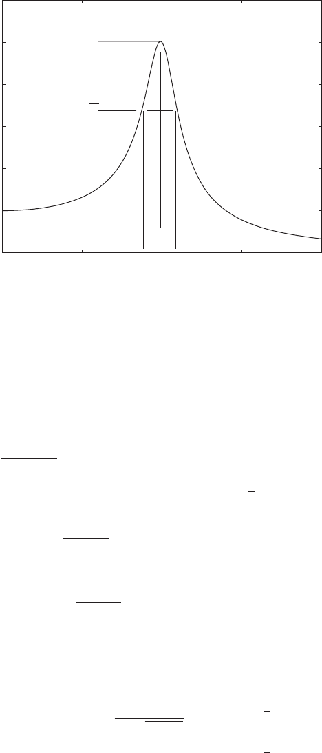
In other words, as shown in Figure 5.18, the cutoff frequencies are at ampli-
tudes that are 3 dB below H
max
. For those systems that have only one cutoff
frequency, the system acts as either a low pass or a high pass filter. A low pass
filter attenuates frequency components in a signal above the cutoff frequency,
and a high pass filter attenuates frequency components in a signal below the
cutoff frequency.
In the design of mechanical systems, there are two different approaches
that are followed, depending on the objective. To reduce vibration levels in a
system, one selects the system parameters so that the excitation frequency is
not in the system’s pass band, because in this region the input is magnified.
(Recall the damping-dominated region of Figure 5.13.) On the other hand,
there is an application area where mechanical filters are designed for insertion
in systems. In this case, one designs the resonance frequency of the system to
be in the frequency range of interest. This enhances sensitivity as discussed
earlier in this section, and is discussed further in Example 8.12.
H12
H
max
12
¢z 100 a
z
2
z
1
z
1
b 100113 1 2 73.2%
¢v
n
100 a
v
n2
v
n1
v
n1
b 100 a
1
13
1 b42.3%
z
2
z
1
13v
n2
v
n1
/ 13
210 CHAPTER 5 Single Degree-of-Freedom Systems Subjected to Periodic Excitations
We now examine the amplitude response H() in light of these defini-
tions. The maximum value of H() occurs at a frequency ratio
max
, which is
a solution of
Thus, we find from Eq. (5.18) that for the nondimensional fre-
quency is
(5.44a)
which means that the corresponding dimensional frequency is
(5.44b)
and for , the amplitude response does not have an extremum, as
is seen in Figure 5.2a. In this case, the maximum value of H() occurs at
0. Therefore,
(5.45) 1 z 1/ 12
H
max
H1
max
2
1
2z21 z
2
z 1/ 12
z 1/ 12
v
max
v
n
21 2z
2
max
21 2z
2
z 1/ 12,
dH1
max
2
d
0
5.3 Frequency-Response Function 211
0 0.5 1 1.5 2
0
1
2
3
4
5
6
H
max
H
max
/√2
Ω
cl
Ω
cu
Ω
max
H(Ω)
Ω
FIGURE 5.18
Definitions of the cutoff frequencies, center frequency, and bandwidth of the amplitude
response of a single degree-of-freedom system.

Cutoff Frequencies of a Filter From Eq. (5.18), the location of the cutoff
frequencies shown in Figure 5.18 is determined by solving
(5.46)
Thus, the upper and lower cutoff frequency ratios are given, respectively, by
(5.47)
where
are the nondimensional cutoff frequencies and v
cu
and v
cl
are the respective
cutoff frequencies in rad/s. The lower cutoff frequency exists only for those
values of z for which
Upon solving for z, we find that
Filter Bandwidth The bandwidth of the system is
(5.48a)
where BW
v
is the bandwidth in rad/s. To determine the bandwidth in Hz, we
have BW
f
BW
v
/2p, and, therefore,
(5.48b)
since
cu
v
cu
/v
n
(2pv
cu
)/(2pv
n
) f
cu
/f
n
and
cl
v
cl
/v
n
(2pv
cl
)/(2pv
n
) f
cl
/f
n
.
Quality Factor Another quantity that is often used to define the band pass
portion of H() when z is small is the quality factor Q, which is given by
(5.49)Q
c
B
w
B
w
cu
for
z 0.3827
B
w
BW
f
v
n
/2p
f
cu
f
cl
f
n
cu
cl
for
z 0.3827
B
w
cu
for
z 0.3827
B
w
BW
v
v
n
v
cu
v
cl
v
n
cu
cl
for
z 0.3827
z 20.5 0.25 12
0.3827.
1 2z
2
2z21 z
2
0
cu
v
cu
v
n
and
cl
v
cl
v
n
cl
21 2z
2
2z11 z
2
cu
21 2z
2
2z11 z
2
H
max
12
1
2z2211 z
2
2
1
211
2
2
2
12z2
2
212 CHAPTER 5 Single Degree-of-Freedom Systems Subjected to Periodic Excitations
where
c
, which is the center frequency ratio, is defined as the geometric mean
of a band pass filter with the nondimensional cutoff frequencies
cl
and
cu
as
(5.50)
The center frequency is not defined for either a low pass or a high pass filter.
When z 0.1, it can be shown that
(5.51)
The error made in using this approximation relative to Eq. (5.49) is 3%, and
this error decreases as z decreases. The different quantities given above are
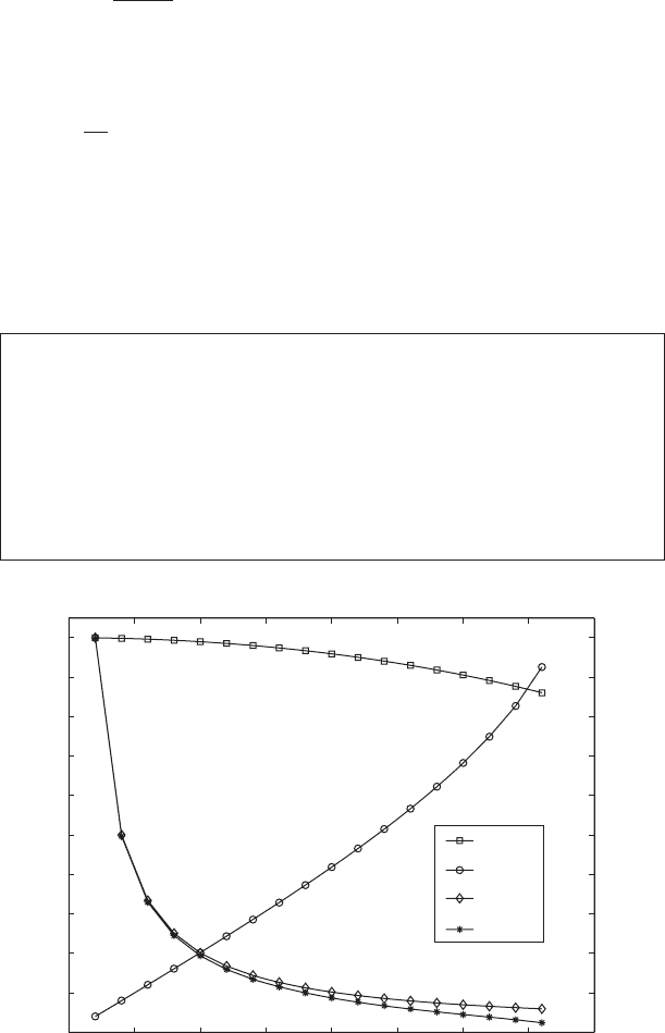
shown in Figure 5.19 as a function of z. We see that for 0 z 0.1, the qual-
ity factor of the system is a measure of the maximum magnification of the
single degree-of-freedom system.
Q
1
2z
c
1
cu
cl
5.3 Frequency-Response Function 213
Design Guideline: The bandwidth of a linear single degree-of-
freedom system is a function of the damping ratio and its natural fre-
quency. For a given natural frequency, the smaller the damping ratio,
the smaller the bandwidth. For a damping ratio less than 0.1, the max-
imum amplitude of system’s transfer function is approximately in-
versely proportional to the damping ratio and the corresponding fre-
quency location is slightly less than the system’s natural frequency.
0 0.05 0.1 0.15 0.2 0.25 0.3 0.35 0.4
0
0.1
0.2
0.3
0.4
0.5
0.6
0.7
0.8
0.9
1
0
5
10
15
20
25
Q, H
max
z
Ω
max
, B
v
Ω
max
B
v
H
max
Q
FIGURE 5.19
Quantities used in the definitions of band pass filters as a function of z.

EXAMPLE 5.6 Damping ratio and bandwidth to obtain a desired Q
It is desired to have a quality factor of 10 for a single degree-of-freedom sys-
tem that has a natural frequency of 25.8 Hz. We shall determine the approxi-
mate damping ratio and bandwidth of the system. Since Q 10, from
Eq. (5.51) we have that z 1/(2 10) 0.05. Then, from Eqs. (5.47), the
upper and lower cutoff frequency ratios are
and from Eq. (5.48b), the bandwidth is
5.3.4 Relationship of the Frequency-Response Function
to the Transfer Function
In Appendix D, a general solution for the response of a vibratory system gov-
erned by Eq. (D.1) was provided. When the initial conditions are zero, it was
shown in Eq. (D.2) that in the Laplace transform domain
(5.52)
The quantity
(5.53)
is called the transfer function of the vibratory system. Here, it is defined in
terms of a force input and a displacement output. The particular form obtained
from Eqs. (5.52), (5.53), and (D.3) is
(5.54)
When the complex variable s is set to jv, we obtain from Eq. (5.54) that
(5.55)
where we have used the identity j
2
1. The function G( jv), sometimes re-
ferred to as G(v), is called the frequency-response function of the vibratory
system governed by Eq. (5.1). This function can be derived from the transfer
G1jv 2
1
k31 1v/v
n
2
2
2jz1v/v
n
24
1
k31 1s/v
n
2
2
2z1s/v
n
24
G1s 2
1
mD1s 2
1
m1s
2
2zv
n
s v
n
2
2
G1s 2
X1s 2
F1s 2
X1s 2
F1s 2/m
D1s 2
25.811.05 0.952 2.58 Hz
BW
f
f
n
B
w
f
n
1
cu
cl
2
cl
21 210.052
2
210.05 211 10.05 2
2
0.95
cu
21 210.052
2
210.05 211 10.05 2
2
1.05
214 CHAPTER 5 Single Degree-of-Freedom Systems Subjected to Periodic Excitations

function as discussed here or, alternatively, by using Fourier transforms of
system input and output signals as discussed later in this section.
On comparing Eq. (5.55) to Eq. (5.35), we recognize that the magnitude
of the complex-valued function kG( jv)—that is, —provides the
amplitude response and the phase response associated with G( jv). Thus,
(5.56a)
and
(5.56b)
When v/v
n
, Eqs. (5.56) for the amplitude and phase response, respec-
tively, take the form
(5.57a)
and
(5.57b)
Equations (5.57) confirm Eqs. (5.18), which were obtained for the amplitude
response and the phase response of a linear vibratory system.
Fourier Transforms and Frequency-Response Functions
Instead of determining the frequency response G( jv) from the transfer func-
tion G(s), the frequency-response function can also be obtained directly based
on the system input and output signals. In order to carry this out, one must use
the Fourier transform.
The Fourier transform enables conversion of information in the time do-
main to its frequency domain counterpart. The definitions of the forward and
inverse Fourier transforms are, respectively,
(5.58)
where f (t) is the signal in the time domain and F( jv) is the corresponding
quantity in the frequency domain.
f 1t 2
1
2p
q
q
F1jv2e
jvt
dv
F1
jv2
q
q
f 1t 2e
jvt
dt
u12
tan
1
2z
1
2
H12
1
211
2
2
2
12z2
2
u1v/v
n
2 tan
1
2zv/v
n
1 1v/v
n
2
2
H1v/v
n
2 0kG1jv 20
1
211 1v/v
n
2
2
2
2
12zv/v
n
2
2
0kG1jv20
5.3 Frequency-Response Function 215

Assuming that the Fourier transforms exist for the input signal f(t) to a vi-
bratory system and the measured output signal x(t), the frequency-response
function is defined as
(5.59a)
Since the displacement and the force signals are present only for t 0,
Eq. (5.59a) reduces to
(5.59b)
Usually, in practice, the following approximation is made
(5.59c)
where the integration is carried out over the record length T.
As with the Laplace transform, there are tables from which one can ob-
tain the Fourier transform and its inverse. Here, we shall present only one
such Fourier transform pair:
(5.60)
where we have used Eqs.(5.57a) and (5.57b) in arriving at Eq. (5.60).
Returning to Eq. (5.58), we see that when f(t) → f(t)u(t), Eq. (5.58)
becomes
(5.61)
which can be obtained from the definition of the Laplace transform by setting
s jv.
The numerical implementation of the Fourier transform given by
Eq. (5.58) is called the discrete Fourier transform (DFT), and a very compu-
tationally efficient algorithm that performs the DFT is the fast Fourier trans-
form (FFT). The DFT is performed over a time interval T
dft
. Thus, we have
two ways to transform the time varying response of a vibratory system to the
frequency domain. In the first method, we take the Laplace transform and
then set s jv. The magnitude of the resulting complex quantity is the am-
plitude response and the corresponding phase angle is the phase response.
This method is limited to linear systems. For those systems in which we ob-
tain the solution numerically or collect digitized signals experimentally, the
F1jv 2
q
0
f 1t 2e
jvt
dt
1
v
2
n
H12e
ju12
f 1t 2
e
zv
n
t
v
d
sin 1v
d
t2u1t 23 F1jv2
1
1zv
n
jv2
2
v
2
d
G1jv2
X1
jv2
F1jv2
T
0
x1t 2e
jvt
dt
T
0
f 1t 2e
jvt
dt
G1
jv2
X1
jv2
F1jv2
q
0
x1t 2e
jvt
dt
q
0
f 1t 2e
jvt
dt
G1
jv2
X1
jv2
F1jv2
q
q
x1t 2e
jvt
dt
q
q
f 1t 2e
jvt
dt
216 CHAPTER 5 Single Degree-of-Freedom Systems Subjected to Periodic Excitations
signals are operated on with the FFT algorithm, which transforms the results
to the frequency domain. We shall employ both techniques in this book.
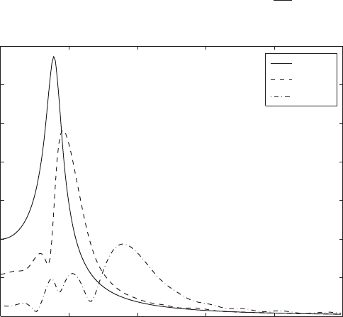
Representative Example
To illustrate the usefulness of the Fourier transform, we return to the system
shown in Figure 4.24, for which the corresponding time-domain results are
shown in Figure 4.25. It was noticed in Figure 4.25 that the introduction of
the spring-stops had the effect of increasing the natural frequency. This was
determined by noticing the decrease in the period of the displacement re-
sponse. Considering the time histories, and using the FFT algorithm,
9
we ob-
tain the corresponding amplitude spectral densities shown in Figure 5.20.
This transformation of information to the frequency domain clearly shows the
changes in the effective natural frequency in the three cases considered. For
m 0, the spectrum indicates a linear response, while for m 1 and
m 10 additional peaks
10
appear in the respective spectra, and there is also
a shift in the peak associated with the system’s natural frequency.
5.3.5 Alternative Forms of the Frequency-Response Function
Consider a single degree-of-freedom system that is subjected to a har-
monic force of the form f(t) F
o
e
jvt
, where . Then, referring to j 11
5.3 Frequency-Response Function 217
9
The MATLAB function fft was used.
10
Whenever spectra of transient motions are determined, there is a broadening effect in the spec-
trum, as seen here.
0 0.2 0.4 0.6 0.8 1
0
10
20
30
40
50
60
70
Ω
|y(Ω)|
m
0
m
1
m
10
FIGURE 5.20
Amplitude density spectrum of the response of the nonlinear system shown in Figure 4.24 to
an initial velocity: V
o
/(v
n
d) 10.

Eqs. (D.61) to (D.67) of Appendix D, we assume a solution of the form
x(t) X
o
()e
jvt
and substitute these expressions into Eq. (5.1) to obtain
where H() and u() are given by Eq. (5.8a). The velocity and acceleration
are, respectively,
The frequency-response function can be defined as the ratio of the dis-
placement response to the applied force in the frequency domain; that is,
This frequency-response function is sometimes referred to as receptance.
In addition to this frequency-response function, there are other frequency-
response function that can be used to describe a vibratory system. They are
as follows.
Mobility
Accelerance
Mechanical Impedance
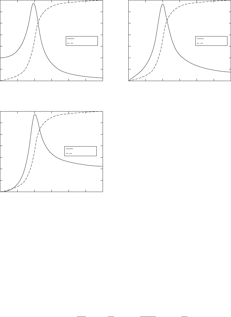
The amplitude and phase of the receptance, mobility, and accelerance func-
tions are plotted in Figure 5.21. These frequency-response functions are used
in experimental modal analysis, where one seeks to identify the parameters of
a vibratory system.
5.4 SYSTEMS WITH ROTATING UNBALANCED MASS
Many rotating machines such as fans, clothes dryers, internal combustion en-
gines, and electric motors have a certain degree of unbalance. In modeling
such systems as single degree-of-freedom systems, it is assumed that the
Mechanical Impedance
Applied force
Velocity
F
o
V
o
1 2
k
vH12
e
j 1u12p/22
Accelerance
Acceleration
Applied force
A
o
1 2
F
o
v
2
k
H12e
j 1u 12p2
Mobility
Velocity
Applied force
V
o
1 2
F
o
v
k
H12e
j 1u 12p/22
Frequency-response function
Displacement
Applied force
X
o
1 2
F
o
1
k
H12e
ju12
x
$
1t 2 A
o
1 2e
jvt
v
2
X
o
1 2e
jvt
v
2
X
o
1 2e
j 1vtp2
x
#
1t 2 V
o
1 2e
jvt
jvX
o
e
jvt
vX
o
1 2e
j1vtp/22
X
o
1 2
F
o
k
H12e
ju12
218 CHAPTER 5 Single Degree-of-Freedom Systems Subjected to Periodic Excitations
unbalance generates a force that acts on the system’s mass. This force, in turn,
is transmitted through the spring and damper to the fixed base, as illustrated
in Figure 3.7. The unbalance is modeled as a mass m
o
rotating with an angu-
lar speed v that is located a fixed distance P from the center of rotation. The
equation describing the motion of this system is given by Eq. (3.35), which is
repeated below.
(5.62a)
d
2
x
dt
2
2zv
n
dx
dt
v
2
n
x
m
o
Pv
2
m
sin vt
F
a
m
sin vt
5.4 Systems with Rotating Unbalanced Mass 219
Magnitude
Phase
3.5
3
2.5
2
1.5
1
0.5
0
0 0.5 1 1.5 2
(a)
2.5 3
0
180
Magnitude
Phase
Phase (degrees)
k(Receptance)
Ω
3.5
3
2.5
2
1.5
1
0.5
0
0 0.5 1 1.5 2
(b)
2.5 3
90
90
Phase (degrees)
k(Mobility)
Ω
Magnitude
Phase
3.5
3
2.5
2
1.5
1
0.5
0
0 0.5 1 1.5 2
(c)
2.5 3
180
0
Phase (degrees)
k(Accelerance)
Ω
FIGURE 5.21
Amplitude and phase responses for z 0.15: (a) receptance; (b) mobility; and (c) accelerance.