Balakumar Balachandran, Magrab E.B. Vibrations
Подождите немного. Документ загружается.

EXAMPLE 5.8 Response of an instrument subjected to base excitation
An instrument is mounted on an isolation system with a damping factor
z 0.3. The base of the instrumentation system is subjected to harmonic mo-
tions at 120 Hz, which is three times higher than the natural frequency of the
system. For the base motion amplitude of 2 cm, we shall determine the peak
acceleration response of the instrument.
The magnitude of the displacement response of the instrument is given
by Eqs. (5.81) and (5.82). Thus,
x
o
y
o
H
mb
() (a)
Since 3 and y
o
0.02 m, Eq. (5.82) is used to determine
(b)
Hence, from Eqs. (a) and (b), we have that the displacement magnitude of the
mass is
x
o
(0.02 m) 0.25 5 mm (c)
Since the displacement response given by Eq. (5.81) is harmonic, the accel-
eration response will also be harmonic and the magnitude of the peak accel-
eration is determined from Eq. (c) and the provided excitation frequency as
a
o
v
2
x
o
(120 2p rad/s)
2
5 10
3
m 2842.5 m/s
2
(d)
H
mb
13 2
21 4 0.3
2
3
2
211 3
2
2
2
4 0.3
2
3
2
0.25
230 CHAPTER 5 Single Degree-of-Freedom Systems Subjected to Periodic Excitations
0 0.5 1 1.5 2 2.5 3
1
0.8
0.6
0.4
0.2
0
0.2
0.4
0.6
0.8
1
Ωt
Amplitude
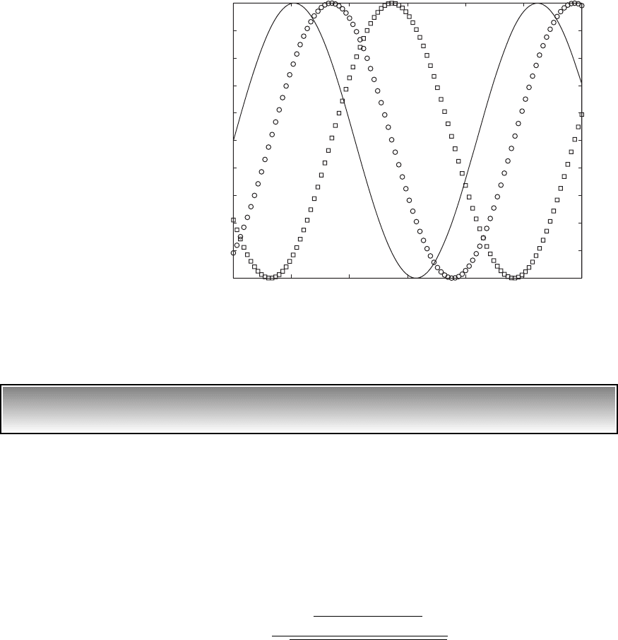
FIGURE 5.29
Phase relationships among displacement, velocity, and force of system with moving base
when 1 and z 0.1. [— y(t)/y
o
; 䊐 x(t)/(2zy
o
/); 䊊 v(t)/(2zy
o
v
n
).]
5.5 Systems with Base Excitation 231
EXAMPLE 5.9 Frequency-response function of a tire for pavement design analysis
A major cause of pavement damage is believed to be due to the vibrations of
heavy trucks, which transmit their loads through the tires to the pavement.
13
Hence, for highway pavement design work, a good model of a tire is needed.
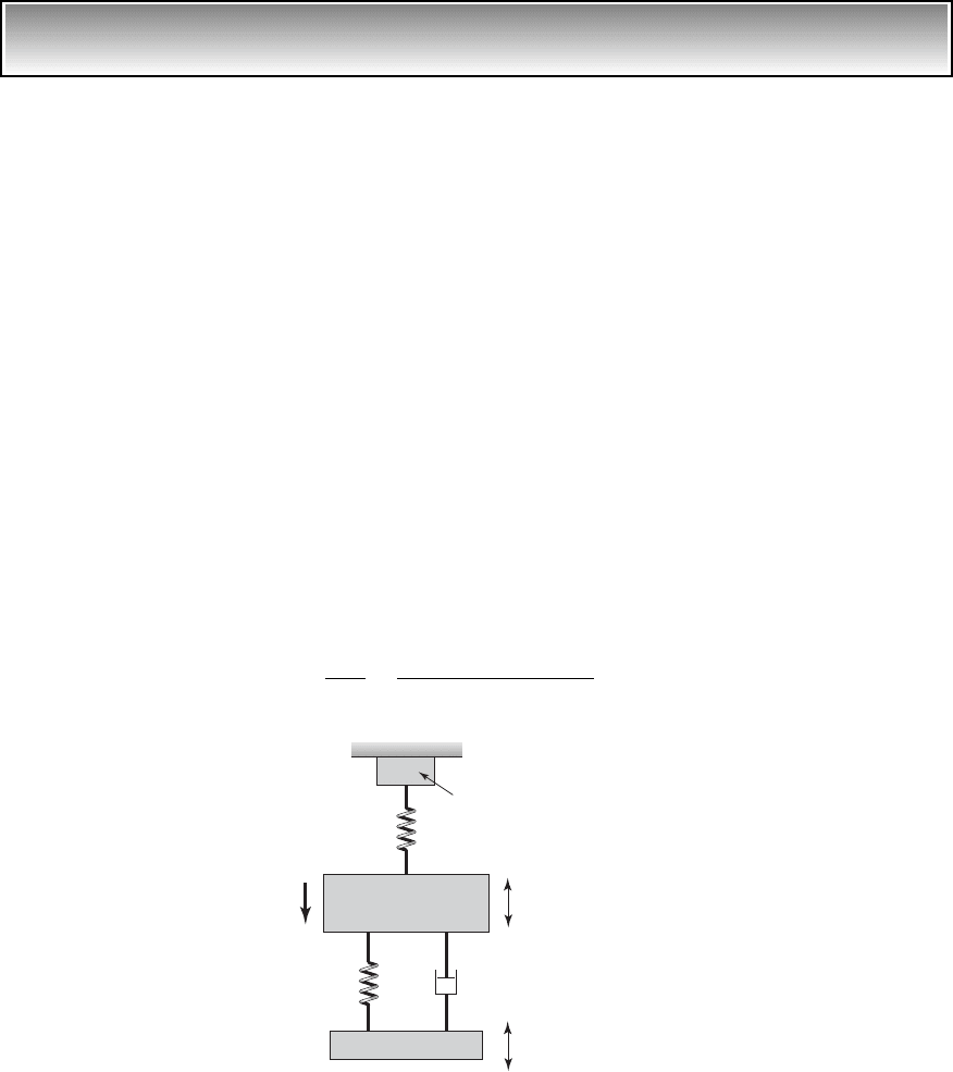
In order to determine this model, the tire is excited by a vibration shaker in
the laboratory by an excitation y(t) and the force f(t) is measured. A repre-
sentative schematic of this system is shown in Figure 5.30, where the tire is
represented by a linear vibratory system with mass m, stiffness k
1
, and damp-
ing c. We shall illustrate how the frequency-response function based on the
displacement input y(t) and the measured force output f(t) can be determined.
First, the governing equation of motion in this system is determined from
a force balance along the j direction, and then, based on this equation, the re-
quired transfer function for this linear system is determined. Subsequently,
the required frequency-response function is obtained. The governing equation
of motion is
(a)
The magnitude of the force f(t) transmitted to the support is given by
f(t) k
2
x(t) (b)
Assuming that the initial conditions are zero, we take the Laplace transforms of
both sides of Eq. (a) and rearrange the resulting transforms to obtain the ratio
(c)
X1s 2
Y1s 2
cs k
1
ms
2
cs 1k
1
k
2
2
mx
$
1k
1
k
2
2x cx
#
k
1
y cy
#
x(t)
y(t)
Mass of wheel and
tire m
k
2
k
1
c
j
Shaker table
Force transduce
r
measuring f(t)
FIGURE 5.30
Model of experimental tire frequency-
response measuring system.
13
J. C. Tielking, “Conventional and wide base radial tyres,” in Proceedings of the Third Interna-
tional Symposium on Heavy Vehicle Weights and Dimensions, D. Cebon and C. G. B. Mitchell,
Eds., Cambridge, U.K., pp. 182–190 (28 June–2 July 1992).

where X(s) is the Laplace transform of x(t) and Y(s) is the Laplace transform
of y(t). From Eq. (b), we find the transform
F(s) k
2
X(s) (d)
where F(s) is the Laplace transform of f(t). From Eqs. (c) and (d), we find the
transfer function between the tire displacement and the force to be
(e)
Based on the discussion of Section 5.3, the frequency-response function is
obtained by setting s jv in Eq. (e) to arrive at frequency-response function
(f)
Usually, in experiments of this type, the magnitude of the frequency-response
function is desired. Then, from Eq. (f), we obtain
(g)
Equation (g) can be used to curve fit the data to determine the tire system pa-
rameters such as the damping coefficient c. In this regard, the discussion re-
lated to Figure 5.15 is applicable.
EXAMPLE 5.10
Electrodynamic vibration exciter
14
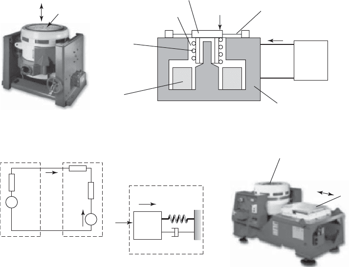
An electrodynamic vibration exciter is used to subject mechanical systems to
known displacement, velocity, or acceleration levels. A typical system is
shown in Figure 5.31 along with the equivalent electrical circuit and the cou-
pled equivalent spring-mass-damper system. The amplifier provides a voltage
u to the drive coil, which is attached to the movable table. The coil has a re-
sistance R
B
and an inductance L. The output resistance of the amplifier is R
A
.
The current i in the drive coil creates a vertical force F
v
that is given by
(a)
where has the units of N/A (Newton per ampere). This force moves the
table. In this example, we will show how to obtain the frequency-response
functions for this system.
The electric circuit equation is
(b)L
di
dt
Ri F
b
u
F
v
i
`
F1
jv2
X1jv 2
` k
2
2k
2
1
v
2
c
2
21k
1
k
2
v
2
m2
2
v
2
c
2
F1jv2
Y1jv2
k
2
1cjv k
1
2
mv
2
cjv 1k
1
k
2
2
F1s 2
Y1s 2
k
2
1cs k
1
2
ms
2
cs 1k
1
k
2
2
232 CHAPTER 5 Single Degree-of-Freedom Systems Subjected to Periodic Excitations
14
G. Buzdugan. E. Miha˘ilescu, and M. Rades¸, Vibration Measurement, Martinus Nijhoff, Dor-
drecht, The Netherlands, 1986, pp. 198–205.
where R R
A
R
B
and the back electromotive force induced in the coil is
given by
15
(c)
The equation of motion of the table system is
(d)
We shall assume that the system undergoes harmonic oscillations in re-
sponse to a harmonic input. Thus, we let
(e)u U
o
e
jvt
x X
o
e
jvt
i I
o
e
jvt
m
1
x
$
c
1
x
#
k
1
x F
v
i
F
b
x
#
5.5 Systems with Base Excitation 233
Amplifier
Support spring k
1
and damper
c
1
i
Drive coil
DC field
coil
Magnetic
material
Table,
m
1
Air gap
(a)
Amplifier
F
b
Γx
.
F
v
Γi
F
v
Γi
u
R
A
R
B
i
Table drive
coil
~
L
Table
c
1
m
1
x
k
1
(b) (c)
Exciter is rotated 90
and attached to the slip
table
Slip tab
le
Table
Electrodynamic
exciter
FIGURE 5.31
(a) Electrodynamic vibration exciter in its normal operating position and a schematic diagram of it; (b) equivalent
electrical circuit and spring-mass-damper system; and (c) slip table. Source: http://www.lds-group.com/home.php
LDS Test and Measurement LLC; http://www.lds-group.com /home.php LDS Test and Measurement LLC
15
It should be noted that has the units of volts (V), since (N/A)(m/s) (Nm/s)/A (VA/A)
V. The mechanical power has the unit of Nm/s, which is equivalent to the electrical power of VA.
x
#

After substituting Eqs. (e) into Eqs. (a) and (b) and taking into account
Eq. (c), we obtain
(f)
Solving for X
o
and I
o
, we obtain
(g)
where
and we have introduced the quantities
where d
o
has the units of meters per volt (m/V). If we assume that the accel-
eration of the table is
we find from the second derivative of x, which is given by Eq. (e), that
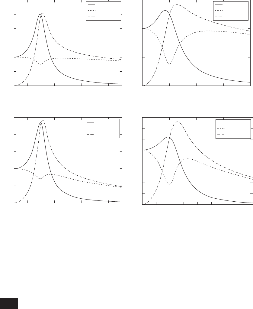
Plots of the normalized values of and are shown in Fig-
ure 5.32. We see that, in order to use the electrodynamic system in a range
where its displacement and acceleration amplitudes are relatively uniform
with frequency, one has to restrict the excitation frequency in the range
1.5. In addition, for the values of these magnitudes to be adequate, one should
design the electrodynamic system with b around 0.15 and a around 0.1.
We also see from these figures that a influences the shapes of the responses
more than b; that is, for a given stiffness k
1
, it is affected more by the current-
producing force parameter than by the electrical properties of the system.
When the mass of the test specimen is large, one has to be concerned with
the static deflection of the table. This can be somewhat compensated for by
increasing the stiffness of the support spring k
1
. However, if the spring is
made too stiff, then the natural frequency of the system will be increased and
the usable frequency range of the electrodynamic excited may be reduced.
The direction of the excitation relative to the position of the test specimen can
be changed by using a slip table, as shown in Figure 5.30c. In this case, the
table rides on a hydrostatic bearing that carries the static load due to the
test specimen, and the force required by the shaker is only that necessary to
0F
v
00A
o
0,0X
o
0,
A
o
v
2
X
o
a A
o
e
jvt
a
2
v
n
k
1
R
,
b
Lv
n
R
, 2z
c
1
2k
1
m
1
v
v
n
, v
n
B
k
1
m
1
,
d
o
k
1
R
D
o
1 2 1
2
11 2zb2 j1a 2z b11
2
22
I
o
U
o
11
2
2jz2
RD
o
1 2
A
X
o
U
o
d
o
D
o
1 2
m
1m
1
v
2
jvc
1
k
1
2X
o
I
o
0
jvX
o
1jvL R 2I
o
U
o
234 CHAPTER 5 Single Degree-of-Freedom Systems Subjected to Periodic Excitations
overcome friction and provide the necessary excitation. However, the direc-
tion of the excitation is transverse to that shown in Figure 5.31a.
5.6 ACCELERATION MEASUREMENT: ACCELEROMETER
An accelerometer is a transducer whose electrical output is proportional to ac-
celeration. It is a very common device used to measure the acceleration of a
point on a system. Accelerometers are constructed in several ways. We shall
5.6 Acceleration Measurement: Accelerometer 235
3
2.5
2
1.5
1
0.5
Magnitude
0
0 0.5 1 1.5 2 2.5 3 3.5 4
X
o
/(U
o
d
o
)
F
v
/(U
o
/R)
A
o
/(
n
2
U
o
d
o
)
1.5
1
0.5
Magnitude
0
0 0.5 1 1.5 2 2.5 3 3.5 4
X
o
/(U
o
d
o
)
F
v
/(U
o
/R)
A
o
/(
n
2
U
o
d
o
)
2.5
2
1.5
1
0.5
Magnitude
0
0 0.5 1 1.5 2 2.5 3
(c)
3.5 4
X
o
/(U
o
d
o
)
F
v
/(U
o
/R)
A
o
/(
n
2
U
o
d
o
)
(a)
(b)
Magnitude
(d)
1.6
1
1.2
1.4
0.4
0.6
0.8
0.2
0
0 0.5 1 1.5 2 2.5 3 3.5 4
X
o
/(U
o
d
o
)
F
v
/(U
o
/R)
A
o
/(
n
2
U
o
d
o
)
FIGURE 5.32
Frequency responses of normalized 0X
o
0, 0A
o
0, and 0F
v
0for z 0.15 and for different system parameter values of a and b:
(a) a 0.1, b 0.15, (b) a 0.5, b 0.15, (c) a 0.1, b 0.5, and (d) a 0.5, b 0.5.
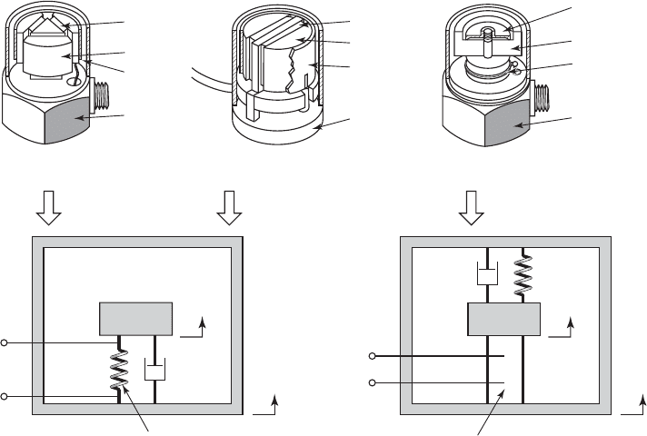
examine one of the more common types, called a piezoelectric accelerometer.
16
A typical piezoelectric accelerometer is constructed in one of the three forms
shown in Figure 5.33. The electrical output of the piezoelectric element is pro-
portional to the change in its length when the piezoelectric element is in com-
pression or it is proportional to the change in shear angle when the element is
in shear. For the compression mounting, the mass is held against the element
by the compression spring, so that as the mass m moves relative to the base by
an amount z, the force on the piezoelectric element either increases or de-
creases. In the shear mount, the movements of the masses shear the elements as
the masses move relative to the base. In this case, the compression of the ele-
ments is not a factor and the stiffness is from the piezoelectric element itself.
The retaining ring ensures that all masses move as a unit. Piezoelectric ele-
ments typically have very low damping factors; that is, 0 z 0.02.
From Eq. (3.31), we make use of the nondimensional time variable t to
arrive at the following equation of motion of a single degree-of-freedom
system with a moving base
236 CHAPTER 5 Single Degree-of-Freedom Systems Subjected to Periodic Excitations
FIGURE 5.33
Piezoelectric accelerometer: (a) and (b) shear type; (c) compression type; (d) single degree-of-freedom model for shear
type; and (e) single degree-of-freedom model for compression type. (B base; M mass; P piezoelectric element;
S spring; R retaining ring.) Source: Courtesy of Bruel & Kjaer Sound and Vibration Measurement A/S.
16
In Chapter 2, a MEMS accelerometer based on the change in capacitance was discussed.
Voltage
output
x(t)
y(t)
m
c
k
(d)
(a) (b) (c)
Voltage
output
x(t)
y(t)
m
c
k
(e)
P
M
R
B
S
M
P
B
P
M
R
B
Piezoelectric
element
Piezoelectric
element

5.6 Acceleration Measurement: Accelerometer 237
(5.95)
where t v
n
t and is the acceleration of the base. If the base is subjected to
a harmonically varying displacement, then
y(t) y
o
sin(t) (5.96)
Upon substituting Eq. (5.96) into Eq. (5.95), we arrive at
(5.97)
where is the acceleration of the base.
The solution to Eq. (5.97) is given by Eq. (5.17). Thus,
z(t) a
o
H()sin(t u()) (5.98)
where H() and u() are given by Eqs. (5.18). We see that the relative dis-
placement of the mass is proportional to the acceleration of the base, and note
that the electrical output voltage from the piezoelectric element is propor-
tional to the relative displacement. Therefore, if the acceleration amplitude re-
sponse and the phase response are to be relatively constant over a wide fre-
quency range, then the parameters of the accelerometer have to be chosen so
that H() varies by less than d, where 1, over that range. From Fig-
ure 5.2 and Eqs. (5.26), it is clear that for 1 the amplitude response and
the phase response are constant. Since H(0) 1 and the damping ratio is very
low, the frequency range is determined from
or
(5.99)
where
a
v
a
/v
n
f
a
/f
n
and f
a
is the frequency below which the amplitude
response varies by less than d. Typical values of f
n
for small accelerometers
are between 50 kHz and 100 kHz.
EXAMPLE 5.11
Design of an accelerometer
We shall determine the working range of an accelerometer with a natural fre-
quency of 60 kHz and whose variation in the amplitude response is less than
2%. Since we want a variation of less than 2% in the amplitude response
of the accelerometer, then d 0.02 and, from Eq. (5.99),
a
0.14. Since
the natural frequency of the accelerometer is 60 kHz, the frequency range
for which the deviation in the amplitude response is less than 2% is f
a
a
B
1
1
1 d
1 d
1
211
2
2
2
12z2
2
1
1
2
0d 0
a
o
v
2
n
y
o
v
2
d
2
z
dt
2
2z
dz
dt
z y
o
2
sin 1t2 a
o
sin 1t2
y
$
d
2
z
dt
2
2z
dz
dt
z
d
2
y
dt
2

(0.14)(60 kHz) 8.4 kHz. In addition, from Figure 5.2 it is seen that the
phase response u() 0 for 0
a
when z is small. Hence, the work-
ing range of the accelerometer is 0 f
a
8.4 kHz.
5.7 VIBRATION ISOLATION
As discussed in Section 5.5, there are many situations in practice that require
one to either isolate a single degree-of-freedom system from transmitting vi-
brations to its base or to isolate a vibrating single degree-of-freedom system
from vibrations of its base. This isolation may be required to reduce the mag-
nitude of the stresses in the support structure to lessen the chances of fatigue-
induced failures or to reduce annoyance from low frequency motions or to
minimize interference with precision measurements and manufacturing pro-
cesses. We shall show that both of these vibration isolation scenarios are
equivalent and that the corresponding design guidelines are the same.
System with Direct Excitation of Inertial Element
We have shown in Eq. (5.17) that the displacement response of a single
degree-of-freedom system whose mass is subjected to a harmonic force is
where H() and u() are given by Eq. (5.18). As discussed in Example 5.7,
the force transmitted to the base (ground) can be written as
(5.100)
Upon substituting Eq. (5.17) into Eq. (5.100), we obtain
(5.101)
where we have used Eq. (D.12) and H
mb
() and c() are given by Eqs.
(5.82). The magnitude of the ratio of the force transmitted to the ground to that
applied to the mass is
(5.102)
System with Base Excitation
Considering a system subjected to base excitation, we see from Eq. (5.81) that
the ratio of the magnitude of displacement of the mass of a single degree-
of-freedom system excited by a harmonic base motion to the magnitude of the
applied displacement is
(5.103)`
x1t 2
y
o
` H
mb
1 2
`
F
T
1t 2
F
o
` H
mb
1 2
F
o
H
mb
1 2sin 1t c122
F
T
1t 2 F
o
H123sin 1t u122 2z cos 1t u1224
F
T
1t 2 kx1t2 cx
#
1t 2 k cx1t2 2z
dx
dt
d
x1t 2
F
o
k
H12sin 1t u122
238 CHAPTER 5 Single Degree-of-Freedom Systems Subjected to Periodic Excitations
Transmissibility Ratio
To minimize the force transmitted to the base from the vibrations of a directly
excited system or to minimize the magnitude of the base motion transmitted
to a system, we require from Eqs. (5.102) and (5.103) that
H
mb
() 1
We define the transmissibility ratio TR as a measure of either the amount
of applied force to the mass that is transmitted to the ground or the amount of
displacement applied to the base that gets transmitted to the mass. Thus,
TR H
mb
() (5.104)
To determine the region in which TR 1, we have to determine the value
of that satisfies
H
mb
() 1
which, after some algebra, results in
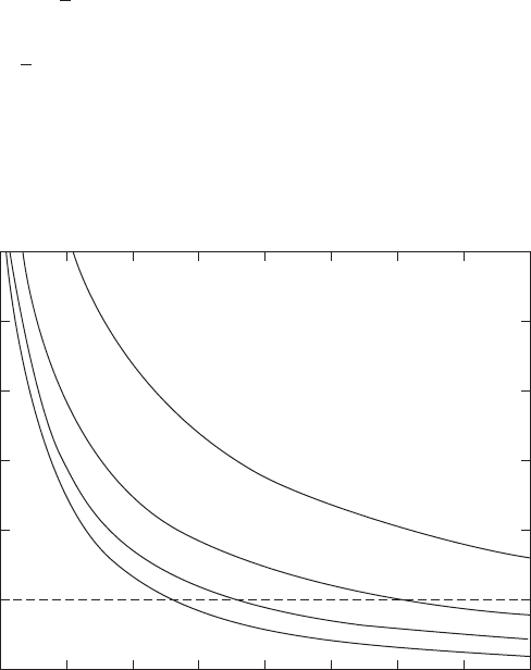
All the different frequency responses obtained for different z intersect at
, as shown in Figure 5.26. By using Eq. (5.104), we now plot the
TR as a percentage as a function of z in Figure 5.34. It is pointed out that Fig-
ure 5.34 is simply an expanded version of Figure 5.26 for 2. This figure
clearly shows that, for a given TR, one should use the least amount of system
damping. For example, when 5.5 and z 0.1, TR 5%; that is, 5% of
the disturbance gets through.
12
12
5.7 Vibration Isolation 239
30
25
20
15
10
5
0
2345
TR (%)
678910
Ω
z
0.4
z 0.2
z 0.1
z 0
FIGURE 5.34
Percentage transmission ratio versus excitation frequency for different damping ratios.