Barber J.R. Intermediate Mechanics of Materials
Подождите немного. Документ загружается.

6.1 Derivation of the shear stress formula 295
In general, if the section crosses the neutral axis only once, the stress there will be
in the same direction as V
y
and the shear flow will continue along the section, dimin-
ishing in magnitude towards the extremities of the section. At all points it remains
locally parallel to the wall of the section.
Example 6. 1
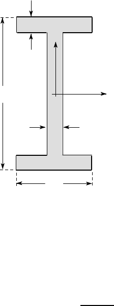
The I-beam of Figure 6.11 is loaded by a vertical shear force of 50 kN. The ap-
propriate centroidal second moment of area for the section is I
x
= 39.4 ×10
6
mm
4
.
Find
(i) the complete distribution of shear stress in the section,
(ii) the maximum shear stress,
(iii) the average vertical shear stress,
(iv) the proportion of the shear force that is carried by the web,
(v) the average shear stress in the web.
20
200
100
20
x
y
O
all dimensions in mm
Figure 6.11
(i) To determine the complete shear stress distribution, we need to make two cuts at
arbitrary points — one in the web and one in the flange as defined in Figure 6.12.
For the web, we use the cut BC of Figure 6.12 (a), obtaining
A
∗
¯y
∗
= A
1
¯y
1
+ A
2
¯y
2
= (80 −y) ×20 ×
(80 + y)
2
+ 100 ×20 ×90
= 244, 000 −20y
2
mm
3
(y in mm)
and hence

296 6 Shear and Torsion of Thin-walled Beams
τ
=
50 ×10
3
×(244,000 −20y
2
)
39.4 ×10
6
×20
= 15.5 −1.27 ×10
−3
y
2
MPa .
x
y
O
B
C
y
A
1
A
2
x
y
O
A
*
*
y
x
D
E
(a) (b)
Figure 6.12: (a) cut BC, (b) cut DE.
For the flange, we use the cut DE of Figure 6.12 (b), obtaining
A
∗
¯y
∗
= x ×20 ×90 = 1800x mm
3
(x in mm)
and hence
τ
=
50 ×10
3
×1800x
39.4 ×10
6
×20
= 0.1142x MPa .
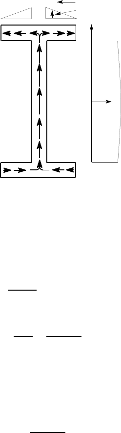
Thus, the shear stress varies linearly in the flanges and quadratically in the web, as
shown in Figure 6.13.
(ii) Since t is the same at all sections, the maximum shear stress occurs in the web at
the neutral axis (y = 0), where A
∗
¯y
∗
is maximum. We obtain
τ
max
= 15.5 MPa .
(iii) The average vertical shear stress is simply the shear force divided by the total
area of the section which is
A = 2 ×100 ×20 + 160 ×20 = 7200 mm
2
.
Hence
τ
ave
=
50 ×10
3
7200
= 6.9 MPa .
6.1 Derivation of the shear stress formula 297
x
y
τ
flange
τ
web
Figure 6.13: Shear stress distribution in the I-beam
(iv) The total shear force carried in the web can be obtained by summing (integrating)
the shear stress over the web. We obtain
F =
Z
80
−80
(15.5 −1.27 ×10
−3
y
2
)20dy = 49,167 N (49 kN) .
Thus the proportion of the shear force carried by the web is
49,167
50,000
= 0.983 (98.3%) .
(v) The average shear stress in the web is
τ
web
ave
=
F
A
web
=
49167
160 ×20
= 15.4 MPa .
Notice, from (iv) above, that almost all the vertical shear force is carried by the
web. Also, there is only a modest variation in shear stress over the web. Even at the
top of the web, where y = 80 mm, the shear stress is 11.4 MPa, from (i) above with
y=80 mm. For this reason, a reasonable estimate of the maximum shear stress in the
I-beam can be obtained very quickly by just dividing the shear force by the web area
— i.e.
τ
max
≈
50,000
160 ×20
= 15.6 MPa ,
which is a very good quick approximation to the correct value obtained in (ii) above.
6.1.2 Location and magnitude of the maximum shear stress
In equation (6.9), only A
∗
, ¯y
∗
and t vary with position in the section and hence the
maximum transverse shear stress occurs at the point where the ratio A
∗
¯y
∗
/t is a max-
imum. Elemental areas dA make a positive contribution to
298 6 Shear and Torsion of Thin-walled Beams
A
∗
¯y
∗
=
ZZ
A
∗
ydA
if and only if y > 0 — i.e. if they are above the neutral axis. It follows that the
maximum value of A
∗
¯y
∗
occurs when the cut is made at the neutral axis, in which
case A
∗
comprises that part of the section above the neutral axis. If the thickness t is
constant, as in Example 6.1, the maximum shear stress will therefore always occur
at the neutral axis.
neutral
plane
A
B
F
L
h
b
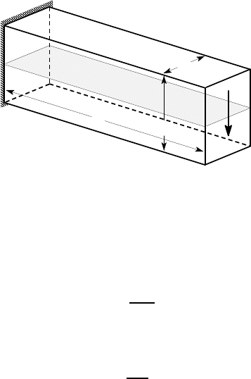
Figure 6.14: Cantilever beam of rectangular cross section
For a beam of rectangular cross section, the transverse shear stresses are always
substantially smaller than the normal stresses due to bending. Consider, for example,
the rectangular cantilever beam of Figure 6.14, loaded by an end force F. Elementary
calculations show that the maximum bending stress occurs along the line AB and is
σ
max
=
6FL
bh
3
(6.10)
and the maximum shear stress, calculated from equation (6.9) occurs at the neutral
plane and is
τ
max
=
3F
2bh
. (6.11)
Thus,
τ
max
will exceed
σ
max
if and only if L<h/4 — i.e. if the beam is only a quarter
as long as its height, which takes the problem well outside the range of application
of beam theory, for which we require L ≫h,b.
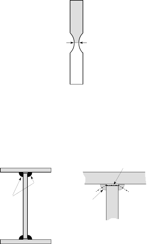
Larger transverse shear stresses will be obtained if the section has a locally re-
duced thickness t, particularly if this occurs at or near to the neutral axis, as shown in
Figure 6.15. However, it is still comparatively rare to encounter an application where
the shear stresses due to shear loading are comparable with those due to bending. For
this reason, it is frequently appropriate in design to neglect shear stresses altogether,
or else to use a crude approximation for them such as
τ
≈V
y
/A or
τ
≈V
y
/A
web
. In
Example 6.1, these approximations gave at least an order of magnitude estimate of
the maximum shear stress and could therefore have been used to determine whether
this magnitude was sufficiently high to justify the effort involved in a more exact
calculation.
6.1 Derivation of the shear stress formula 299
A
*
t
Figure 6.15: Beam with a reduced thickness at the neutral axis
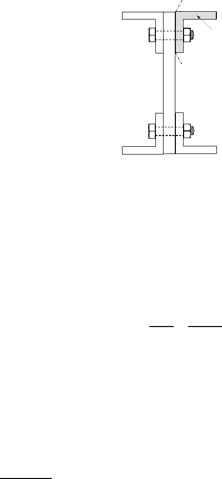
6.1.3 Welds, rivets and bolts
There are not many applications where we would need to use a beam with a locally
reduced thickness t, but a similar effect is produced when a beam is fabricated by
welding three plates together as shown in Figure 6.16 (a). In this case, the thickness
at the weld may be smaller than that of the rest of the section. Also, the stresses in
the weld are of particular interest, since the weld material may contain defects and
hence be weaker than the rest of the material.
welds
air gap
cut
weld
(a) (b)
Figure 6.16: A beam fabricated from three rectangular plates
To determine the maximum shear stress in the weld, we make the shortest cut
that would be sufficient to cause the flange to drop off, since the cut must separate
the section into two parts in view of the argument of §6.1. This can be achieved by
cutting through both welds as shown in Figure 6.16 (b).
300 6 Shear and Torsion of Thin-walled Beams
Notice that the cut doesn’t even have to be a plane or to be connected. The thick-
ness t is the total length along the cut line, not including air. Here we would get twice
the smallest thickness through the weld.
5
cut
A
*
Figure 6.17: A beam assembled with bolts
A similar technique can be used if rivets or bolts are used to attach the flange
instead of welds, as shown in Figure 6.17. This time, we imagine cutting through
the bolts to make one angle drop off. However, we cannot define a thickness t here,
since the angle is joined to the rest of the section by a set of discrete areas. Instead,
we must go back to the concept of shear flow q, which is the horizontal shear force
per unit length transmitted through the bolts. This must be transmitted through the
total bolt cross-sectional area per unit length, which in turn is the cross-sectional area
of one bolt multiplied by the number of bolts N per unit length. If the bolts are of
diameter d, we have a shear area of
π
Nd
2
/4 per unit length and the average shear
stress in the bolts is therefore
τ
bolts
=
4q
π
d
2
N
=
4V
y
A
∗
¯y
∗
π
d
2
NI
x
, (6.12)
where we note that A
∗
and ¯y
∗
relate to the section that would be removed by the cut,
as in more conventional problems.
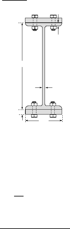
Example 6. 2
Figure 6.18 shows a W610×101 I-beam that has been stiffened against bending by
the attachment of two 230×25 mm rectangular plates. The plates are secured to the I-
beam by 10 mm diameter bolts with an axial spacing of 100 mm. The second moment
of area of the I-beam without the stiffeners is 764×10
6
mm
4
. Find the average shear
stress in the bolts if the beam transmits a shear force of 50 kN.
5
In calculating the shear stress for this cut using equation (6.9), we can neglect the small
contribution to A
∗
¯y
∗
from the fragments of weld adhering to the section removed.
6.1 Derivation of the shear stress formula 301
We first calculate the second moment of area I
x
for the stiffened section, using
the parallel axis theorem, with the result
I
x
= 764 ×10
6
+ 2
230 ×25
3
12
+ 230 ×25 ×314
2
= 1898 ×10
6
mm
4
.
25
14.9
603
230
10.5
Figure 6.18
If we cut through the top flange bolts, the area cut off (A
∗
) is 230×25 and
A
∗
¯y
∗
= 230 ×25 ×314 = 1.806 ×10
6
mm
3
.
The axial bolt spacing is 100 mm and there are two bolts at each axial location,
so the number of bolts per unit length is
N =
2
100
= 0.02 bolts per mm .
Substituting these results into equation (6.12), we obtain
τ
bolts
=
4 ×50, 000 ×1.806 ×10
6
π
×10
2
×0.02 ×1898 ×10
6
= 30 MPa .
6.1.4 Curved sections
If a thin-walled beam contains curved sections, the procedure for determining the
transverse shear stress is the same, but integration will generally be needed in deter-
mining I
x
and A
∗
¯y
∗
. We illustrate this with the example of the semicircular section of
Figure 6.19, with radius a and thickness t, where t ≪a.
To determine I
x
, we consider a small element dA =atd
θ
shown shaded in Figure
6.19. Then
302 6 Shear and Torsion of Thin-walled Beams
I
x
=
ZZ
A
y
2
dA =
Z
π
/2
−
π
/2
(asin
θ
)
2
atd
θ
= a
3
t
Z
π
/2
−
π
/2
sin
2
θ
d
θ
=
π
a
3
t
2
. (6.13)
Notice that I
x
is a property of the whole section, so the integral is performed over the
entire semi-circle from end to end.
θ
dθ
a
O
t
adθ
Figure 6.19: Thin-walled semi-circular cross section
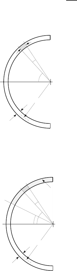
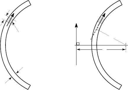
We now make a cut at a general point
θ
=
φ
to determine the shear stress, as
shown in Figure 6.20.
θ
φ
dθ
a
cut
dA
O
t
*
A
Figure 6.20: Cut for determining the shear stress in the semi-circular section
6.2 Shear centre 303
The quantity A
∗
¯y
∗
relates only to the section cut off, which is defined by
φ
<
θ
<
π
/2. These are therefore the limits of integration.
6
We obtain
A
∗
¯y
∗
=
Z
π
/2
φ
ydA =
Z
π
/2
φ
(asin
θ
)atd
θ
= a
2
t cos
φ
. (6.14)
It is important to ensure that the limits of integration correspond to the edges of the
area A
∗
and that the lower limit is smaller than the upper limit.
The shear stress at the point
θ
=
φ
is
τ
=
V
y
A
∗
¯y
∗
I
x
t
=
V
y
×(a
2
t cos
φ
)
(
π
a
3
t/2) ×t
=
2V
y
cos
φ
π
at
. (6.15)
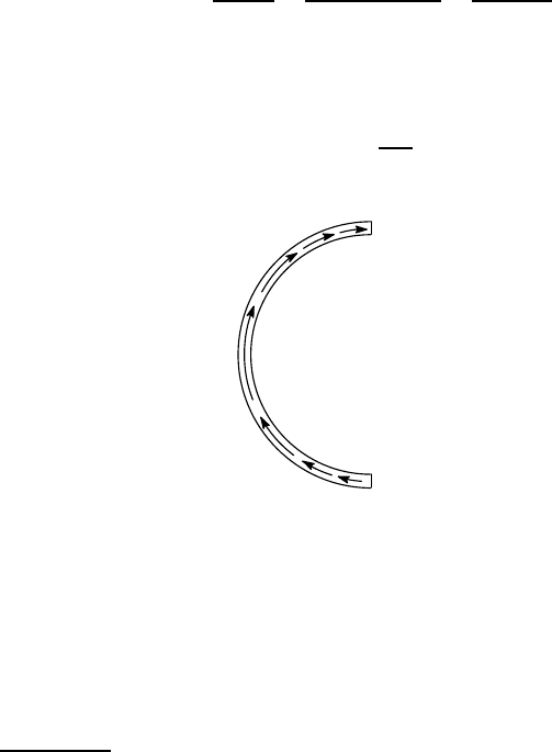
We see from equation (6.15) that the shear stress varies sinusoidally around the
section from zero at the ends (
φ
= ±
π
/2) to a maximum at the neutral axis (
φ
= 0),
given by
τ
max
=
2V
y
π
at
. (6.16)
It is parallel to the section wall at all points, as shown in Figure 6.21.
Figure 6.21: Shear stress distribution for the semi-circular section
6.2 Shear centre
The theory presented above gives a unique solution for the shear stress throughout the
section for a given value of V
y
. This implies that the line of action of V
y
is prescribed,
since the distribution of
τ
over the section has a resultant in magnitude, direction and
line of action.
6
Notice that it is necessary to define two indefinite angles
θ
,
φ
in order to calculate the stress
at a general point. One of these angles (
φ
) defines the point under consideration and the
other (
θ
) serves as a variable of integration in the summation for A
∗
¯y
∗
. A common error
is to use only one such variable and then use definite limits in the integration. At best, this
will only yield the stress at a particular point.
304 6 Shear and Torsion of Thin-walled Beams
If the actual shear force applied has a different line of action from that implied
by the theoretical distribution, there will be some twisting of the section and a more
complex shear stress distribution will be developed.
There is a unique point C for any given beam section, such that if the line of
action of V passes through C, the section does not twist. This point is called the
shear centre. For a doubly-symmetric section, like an I-beam, the shear centre will
coincide with the intersection between the two axes of symmetry. For sections with
one axis of symmetry, the shear centre lies on that axis, but it’s location must be
found by determining the line of action of the shear force implied by the distribution
of shear stress from the preceding analysis.
6.2.1 Finding the shear centre
To find the shear centre of a thin-walled section, we must determine the line of action
of the resultant force due to the shear stress distribution
τ
of equation (6.9). The shear
stress is everywhere locally parallel to the thin wall and it generates an elemental
force dF =
τ
dA on the elemental area dA shown in Figure 6.22 (a). We can write
dA=tdS, where dS is an element of the perimeter and hence
dF =
τ
tdS = qdS . (6.17)
t
dS
dF
dA
O
c
V
y
C
dF
n
(a) (b)
Figure 6.22: (a) The elemental force dF, (b) definition of the dimensions c and n
The shear force V
y
is the resultant of the elemental forces dF and it must therefore
have the same moment about any point O. We conclude that
V
y
c =
Z
S
ndF =
Z
S
n
τ
tdS =
Z
S
nqdS , (6.18)
where the integration is performed over the entire perimeter of the section, c defines
the location of the shear centre and n is the moment arm for the elemental force dF,
i.e. the perpendicular distance from O to the line of action of dF (the local tangent
to the mean line of the section), as shown in Figure 6.22 (b).