Bhushan B. Handbook of Micro/Nano Tribology, Second Edition
Подождите немного. Документ загружается.

© 1999 by CRC Press LLC
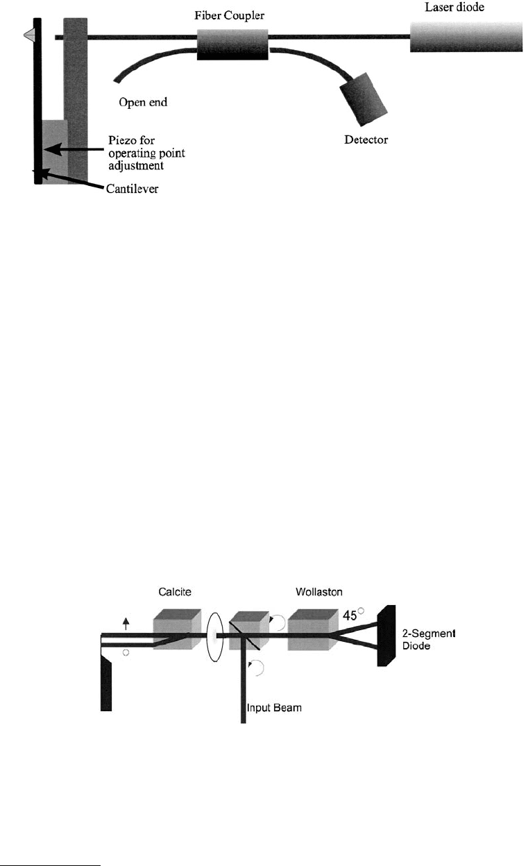
big problem since only 4% of the light is reflected at the end of the fiber, at the glass–air interface. The
two reflected light waves interfere with each other. The product is guided back into the fiber coupler and
again split into two parts. One half is analyzed by the photodiode. The other half is fed back into the
laser. Communications-grade laser diodes are sufficiently resistant against feedback to be operated in
this environment. They have, however, a bad coherence length, which in this case does not matter, since
the optical path difference is in any case no larger than 5 µm. Again, the end of the fiber has to be
positioned on a piezo drive to set the distance between the fiber and the cantilever to λ (n + ¼).
2.3.1.4 Nomarski Interferometer
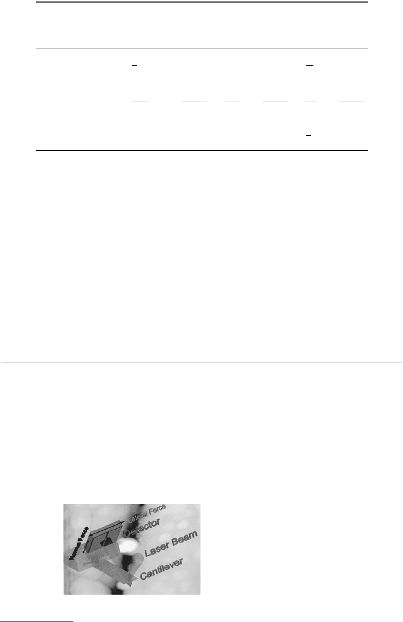
Another solution to minimize the optical path difference uses the Nomarski (Schönenberger and Alva-
rado, 1989). Figure 2.10 depicts a sketch of the microscope. The light of a laser is focused on the cantilever
by a lens. A birefringent crystal (for instance, calcite) between the cantilever and the lens with its optical
axis 45° off the polarization direction of the light splits the light beam into two paths, offset by a distance
given by the length of the birefringent crystal. Birefringent crystals have varying indexes of refraction. In
calcite, one crystal axis has a lower index than the other two. This means that certain light rays will
propagate at a different speed through the crystal than others. By choosing a correct polarization, one
can select the ordinary ray, the extraordinary ray, or one can get any distribution of the intensity among
those two rays. A detailed description of birefringence can be found in textbooks (Shen, 1984). A calcite
crystal deflects the extraordinary ray at an angle of 6° within the crystal. By choosing a suitable length
of the calcite crystal, any separation can be set.
FIGURE 2.9 A typical setup for a fiber-optic interferometer readout.
FIGURE 2.10 Principle of the Nomarski AFM (Schönenberger and Alvarado, 1989, 1990). The circular polarized
input beam is deflected to the left by a nonpolarizing beam splitter. The light is focused onto a cantilever. The calcite
crystal between the lens and the cantilever splits the circular polarized light into two spatially separated beams with
orthogonal polarizations. The two light beams reflected from the lever are superimposed by the calcite crystal and
collected by the lens. The resulting beam is again circular polarized. A Wollaston prism produces two interfering
beams with a π/2 phase shift between them. The minimal path difference accounts for the excellent stability of this
microscope.
© 1999 by CRC Press LLC
The focus of one light ray is positioned near the free end of the cantilever while the other is placed
close to the clamped end. Both arms of the interferometer pass through the same space, except for the
distance between the calcite crystal and the lever. The closer the calcite crystal is placed to the lever, the
less influence disturbances like air currents have.
2.3.2 Sensitivity
Sarid (1991) has given values for the sensitivity of the different interferometeric detection systems.
Table 2.2 shows a summary of his results.
2.4 Optical Lever
The most common cantilever deflection detection system is the optical lever (Meyer and Amer, 1988;
Alexander et al., 1989). This method, depicted in Figure 2.11, employs the same technique as light beam
deflection galvanometers. A fairly well collimated light beam is reflected off a mirror and projected to a
receiving target. Any change in the angular position of the mirror will change the position where the
light ray hits the target. Galvanometers use optical path lengths of several meters and scales projected to
the target wall as a readout help.
For the AFM using the optical lever method, a photodiode segmented into two (or four) closely spaced
devices detects the orientation of the end of the cantilever (see Figure 2.11). Initially, the light ray is set
to hit the photodiodes in the middle of the two subdiodes. Any deflection of the cantilever will cause an
imbalance of the number of photons reaching the two halves. Hence, the electrical currents in the
TABLE 2.2 Noise in Interferometers
Homodyne
Interferometer,
Fiber-Optic
Interferometer
Heterodyne
Interferometer
Nomarski
Interferometer
Laser noise 〈δi
2
〉
L
Thermal noise 〈δi
2
〉
l
Shot noise 〈δi
2
〉
S
4eηP
d
B 2eη(P
R
+ P
S
)B
F is the finesse of the cavity in the homodyne interferometer, P
i
is the incident power, P
d
is the
power on the detector, η is the sensitivity of the photodetector, and RIN is the relative intensity noise
of the laser. P
R
and P
S
are the power in the reference and sample beam in the heterodyne interferometer.
P is the power in the Nomarsky interferometer, and δΘ is the phase difference between the reference
and the probe beam in the Nomarsk y interferometer. B is the bandwidth and e the electron charge.
λ is the wavelength of the laser and k the stiffness of the cantilever, T is the temperature.
FIGURE 2.11 Optical lever setup.
1
4
222
η FP
i
RIN
η
22 2
PP
RS
+
()
RIN
1
16
22
ηδP Θ
16
4
2
2
222
0
π
λ
η
ω
FP
k TBQ
k
i
B
4
4
2
2
22
0
π
λ
η
ω
P
k TBQ
k
d
B
π
λ
η
ω
2
2
22
0
4
P
k TBQ
k
B
1
2
ePBη
© 1999 by CRC Press LLC
photodiodes will be unbalanced, too. The difference signal is further amplified and is the input signal to
the feedback loop. Unlike the interferometric AFMs, where often a modulation technique is necessary
to get a sufficient signal-to-noise ratio, most AFMs employing the optical lever method are operated in
a static mode. AFMs based on the optical lever method are universally used. It is the simplest method
to construct an optical readout and it can be confined in volumes smaller than 5 cm on the side.
The optical lever detection system is a simple yet elegant way to detect normal and lateral force signals
simultaneously (Meyer and Amer, 1988, 1990; Alexander et al., 1989; Marti, Colchero et al., 1990). It has
the additional advantage that it is a remote detection system.
2.4.1 Implementations
Light from a laser diode or from a superluminescent diode is focused on the end of the cantilever. The
reflected light is directed onto a quadrant diode that measures the direction of the light beam. A Gaussian
light beam far from its waist is characterized by an opening angle β. The deflection of the light beam by
the cantilever surface tilted by an angle α is 2α. The intensity on the detector then shifts to the side by
the product of 2α and the separation between the detector and the cantilever. The readout electronics
calculates the difference of the photocurrents. The photocurrents, in turn, are proportional to the intensity
incident on the diode.
The output signal is hence proportional to the change in intensity on the segments:
(2.50)
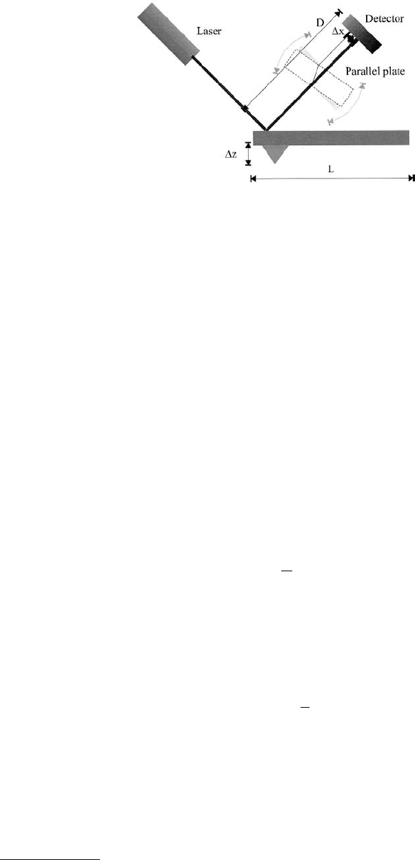
Figure 2.12 shows a schematic drawing of the optical lever setup. For the sake of simplicity, we assume
that the light beam is of uniform intensity with its cross section increasing proportionally with the
distance between the cantilever and the quadrant detector. The movement of the center of the light beam
is then given by
(2.51)
The photocurrent generated in a photodiode is proportional to the number of incoming photons hitting
it. If the light beam contains a total number of N
0
photons, then the change in difference current becomes
(2.52)
FIGURE 2.12 The setup of optical lever detection microscope.
II
sig tot
∝ 4
α
β
∆∆xz
d
Det
=
l
∆∆∆I I I zdN
RL
−
()
==const
0
© 1999 by CRC Press LLC
Combining Equations 2.51 and 2.52, one obtains that the difference current ∆I is independent of the
separation of the quadrant detector and the cantilever. This relation is true if the light spot is smaller
than the quadrant detector. If it is greater, the difference current ∆I becomes smaller with increasing
distance. In reality, the light beam has a Gaussian intensity profile. For small movements ∆x (compared
with the diameter of the light spot at the quadrant detector), Equation 2.52 still holds. Larger movements
∆x, however, will introduce a nonlinear response. If the AFM is operated in a constant-force mode, only
small movements ∆x of the light spot will occur. The feedback loop will cancel out all other movements.
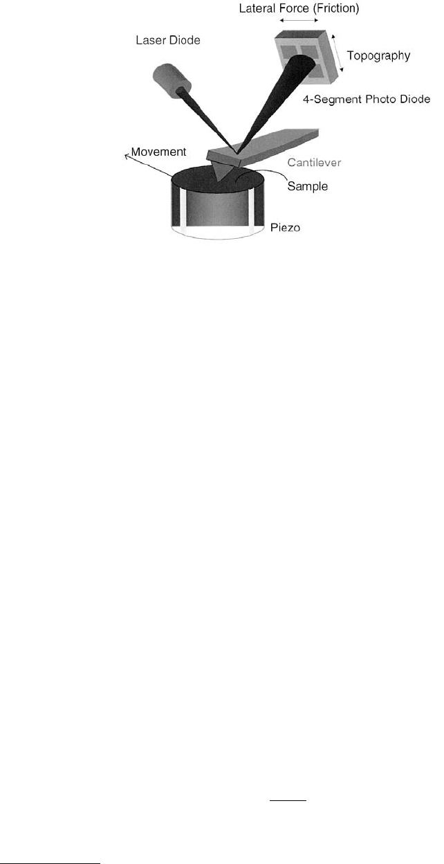
The scanning of a sample with an AFM can twist the microfabricated cantilevers because of lateral
forces (Mate et al., 1987; Marti et al., 1990; Meyer and Amer, 1990) and affect the images (den Boef,
1991). When the tip is subjected to lateral forces, it will twist the lever, and the light beam reflected from
the end of the lever will be deflected perpendicular to the ordinary deflection direction. For many
investigations, this influence of lateral forces is unwanted. The design of the triangular cantilevers stems
from the desire to minimize the torsion effects. However, lateral forces open up a new dimension in force
measurements. They allow, for instance, a distinction of two materials because of the different friction
coefficient, or the determination of adhesion energies. To measure lateral forces the original optical lever
AFM has to be modified; Figure 2.13 shows a sketch of the instrument. The only modification compared
with Figure 2.12 is the use of a quadrant detector photodiode instead of a two-segment photodiode and
the necessary readout electronics. The electronics calculates the following signals:
(2.53)
The calculation of the lateral force as a function of the deflection angle does not have a simple solution
for cross sections other than circles. An approximate formula for the angle of twist for rectangular beams
is (Baumeister and Marks, 1967)
(2.54)
FIGURE 2.13 Scanning force and friction microscope (SFFM). The lateral forces exerted on the tip by the moving
sample cause a torsion of the lever. The light reflected from the lever is deflected orthogonally to the deflection caused
by normal forces.
UIIII
UIIII
Normal Force Upper Left Upper Right Lower Left Lower Right
Lateral Force Upper Left Upper Left Lower Right Lower Right
=+
()
−+
()
[]
=+
()
−+
()
[]
α
β
Θ=
M
Gb h
t
l
β
3

© 1999 by CRC Press LLC
where M
t
= Fa is the external twisting moment due to friction, l is the length of the beam, b and h the
sides of the cross section, G the shear modulus, and β a constant determined by the value of h/b. For the
equation to hold, h has to be larger than b.
Inserting the values for a typical microfabricated lever with integrated tips
(2.55)
into Equation 2.54, we obtain the relation
(2.56)
Typical lateral forces are of order 10
–10
N.
2.4.2 Sensitivity
The sensitivity of this setup has been calculated in various papers (Colchero et al., 1991; Sarid, 1991;
Colchero, 1993), to name just three examples. Assuming a Gaussian beam, the resulting output signal as
a function of the deflection angle is dispersion like. Equation 2.50 shows that the sensitivity can be
increased by increasing the intensity of the light beam I
tot
or by decreasing the divergence of the laser
beam. The upper bound of the intensity of the light I
tot
is given by saturation effects on the photodiode.
If we decrease the divergence of a laser beam, we automatically increase the beam waist. If the beam waist
becomes larger than the width of the cantilever, we start to get diffraction. Diffraction sets a lower bound
on the divergence angle. Hence, one can calculate the optimal beam waist w
opt
and the optimal divergence
angle β (Colchero et al., 1991; Colchero, 1993)
(2.57)
where b is the width of the cantilever and λ is the wavelength of the light. The optimal sensitivity of the
optical lever then becomes
(2.58)
The angular sensitivity optical lever can be measured by introducing a parallel plate into the beam. A
tilt of the parallel plate results in a displacement of the beam, mimicking an angular deflection.
Additional noise source can be considered. Of little importance is the quantum mechanical uncertainty
of the position (Colchero et al., 1991; Colchero, 1993), which is for typical cantilevers at room temperature
b =×
×
×
−
610
7
m
h =10 m
=10 m
a = 3.3 10 m
G=5 10 Pa
= 0.333
-5
-4
-6
10
l
β
FN
Lateral Force
=× ×
−
11 10
4
. Θ
wb
b
opt
opt
≈
≈
036
089
.
.θ
λ
ε
λ
mW rad mW
tot
[]
=
[]
18.
b
I
© 1999 by CRC Press LLC
(2.59)
At very low temperatures and for high-frequency cantilevers, this could become the dominant noise
source. A second noise source is the shot noise of the light. The shot noise is related to the particle
number. We can calculate the number of photons incident on the detector
(2.60)
where I is the intensity of the light, τ the measurement time, B = 1/τ the bandwidth, c the speed of light,
and λ the wavelength of the light. The shot noise is proportional to the square root of the number of
particles. Equating the shot noise signal with the signal resulting for the deflection of the cantilever, one
obtains
(2.61)
where w is the diameter of the focal spot. Typical AFM setups have a shot noise of 2 pm. The thermal
noise can be calculated from the equipartition principle. The amplitude at the resonance frequency is
(2.62)
where Q is the quality of the cantilever resonance, ω
0
the resonance frequency, and k is the stiffness of
the cantilever spring. A typical value is 16 pm. Upon touching the surface, the cantilever increases its
resonance frequency by a factor of 4.39. This results in a new thermal noise amplitude of 3.2 pm for the
cantilever in contact with the sample.
2.5 Piezoresistive Detection
2.5.1 Implementations
An alternative detection system which is not as widespread as the optical detection schemes are piezore-
sistive cantilevers (Ashcroft and Mermin, 1976; Stahl et al., 1994; Kassing and Oesterschulze, 1997). These
levers are based on the fact that the resistivity of certain materials, in particular of Si, changes with the
applied stress. Figure 2.14 shows a typical implementation of a piezoresistive cantilever. Four resistances
are integrated on the chip, forming a Wheatstone bridge. Two of the resistors are in unstrained parts of
the cantilever; the other two are measuring the bending at the point of the maximal deflection. For
instance, when an AC voltage is applied between terminals A and C one can measure the detuning of
the bridge between terminals B and D. With such a connection, the output signal varies only due to bending,
but not due to changing of the ambient temperature and thus the coefficient of the piezoresistance.
2.5.2 Sensitivity
The resistance change is (Kassing and Oesterschulze, 1997)
(2.63)
∆z
m
==
h
2
005
0
ω
.fm
n
II
Bc
I
B
==
π
=×
[]
[]
τ
ω
λ
hh2
18 10
9
.
W
Hz
∆z
w
B
I
shot
kHz
mW
fm=
[]
[]
[]
68
l
∆z
B
kQ
therm
Nm
pm=
[]
[]
129
0
ω
∆R
R
0
=Πδ
© 1999 by CRC Press LLC
where ∏ is the tensor element of the piezoresistive coefficients, δ the mechanical stress tensor element,
and R
0
the equilibrium resistance. For a single resistor, they separate the mechanical stress and the tensor
element in longitudinal and transversal components.
(2.64)
The maximum value of the stress components are ∏
t
= –64.0 × 10
–11
m
2
/N and ∏
l
= 71.4 × 10
–11
m
2
/N
for a resistor oriented along the (110) direction in silicon (Kassing and Oesterschulze, 1997). In the
resistor arrangement of Figure 2.14 two of the resistors are subject to the longitudinal piezoresistive effect
and two of them are subject to the transversal piezoresistive effect. The sensitivity of that setup is about
four times that of a single resistor, with the advantage that temperature effects cancel to first order. It is
then calculated that
(2.65)
where the geometric constants are defined in Figure 2.1, F is the normal force applied to the end of the
cantilever, ∆z is the deflection resulting from this force, and ∏ = 67.7 × 10
–11
m
2
/N
is the averaged
piezoresistive coefficient. Plugging in typical values for the dimensions ( = 100 µm, b = 10 µm, h =
1 µm), one obtains that
(2.66)
The sensitivity can be tailored by optimizing the dimensions of the cantilever.
2.6 Capacitive Detection
The capacitance of an arrangement of conductors depends on the geometry. Generally speaking, the
capacitance increases for decreasing separations. Two parallel plates form a simple capacitor (see
Figure 2.15, upper left), with the capacitance
(2.67)
FIGURE 2.14 A typical setup for a piezoresistive readout.
∆R
R
tt ll
0
=Π +Πδδ
∆
∆
R
R
Eh
z
bh
F
0
22
3
2
6
=Π =Π
l
l
∆R
R
F
0
5
410
=
×
−
nN
C
A
x
=
εε
0
© 1999 by CRC Press LLC
where A is the area of the plates, assumed equal, and x the separation. Alternatively, one can consider a
sphere vs. an infinite plane (see Figure 2.15, lower left). Here, the capacitance is (Sarid, 1991)
(2.68)
where R is the radius of the sphere and α is defined by
(2.69)
One has to keep in mind that capacitance of a parallel plate capacitor is a nonlinear function of the
separation. Using a voltage divider, one can circumvent this problem.
Figure 2.16a shows a low-pass filter. The output voltage is given by
(2.70)
Here, C is given by Equation 2.67, ω is the excitation frequency, and j is the imaginary unit. The
approximate relation in the end is true when ωCR 1. This is equivalent to the statement that C is fed
by a current source, since R must be large in this setup. Plugging this equation into Equation 2.70 and
neglecting the phase information, one obtains
(2.71)
which is linear in the displacement x.
FIGURE 2.15 Three possible arrangements of a capacitive readout.
The upper left shows the cross section through a parallel plate capac-
itor. The lower left shows the geometry sphere vs. the plane. The
right side shows the more-complicated, but linear capacitive readout.
FIGURE 2.16 Measuring the capacitance. The left side (a) shows a low-pass filter; the right side (b) shows a
capacitive divider. C (left) or C
2
are the capacitances under test.
CR
n
n
=π
()
()
=
∞
∑
4
0
2
ε
α
α
sinh
sinh
α=++ +
ln 1 2
2
2
z
R
z
R
z
R
UU
jC
R
jC
U
jCR
U
jCR
out
=
+
=
+
≅
≈≈
≈
1
1
1
1
ω
ω
ωω
U
Ux
RA
out
=
≈
ωεε
0
© 1999 by CRC Press LLC
Figure 2.16b shows a capacitive divider. Again, the output voltage U
out
is given by
(2.72)
If there is a stray capacitance C
s,
then it modifies Equation 2.72 to
(2.73)
Provided C
s
+ C
1
C
2
, one has a system that is linear in x. The driving voltage U
≈
has to be large (more
than 100 V) to have the output voltage in the range of 1 V. The linearity of the readout depends on the
capacitance C
1
(Figure 2.17).
Another idea is to keep the distance constant and to change the relative overlap of the plates (see
Figure 2.15, right side). The capacitance of the moving center plate vs. the stationary outer plates becomes
(2.74)
where the variables are defined in Figure 2.15. The stray capacitance C
stray
comprises all effects, including
the capacitance of the fringe fields. When length x is comparable to the width b of the plates, one can
safely assume that the stray capacitance C
stray
is constant, independent of x. The main disadvantage of
this setup is that it is not as easily incorporated in a microfabricated device as the others.
FIGURE 2.17 Linearity of the capacitance readout as a function of the reference capacitor.
UU
C
CC
U
C
A
x
C
out
=
+
=
+
≈≈
1
21
1
0
1
εε
UU
C
A
x
CC
s
out
=
++
≈
1
0
1
εε
CC
bx
s
=+
stray
2
0
εε
© 1999 by CRC Press LLC
2.6.1 Sensitivity
The capacitance itself is not a measure of the sensitivity, but its derivative is indicative of the signals one
can expect. Using the situation described in Figure 2.15, upper left, and in Equation 2.67, one obtains
for the parallel plate capacitor
(2.75)
Assuming a plate area A of 20 µm by 40 µm and a separation of 1 µm, one obtains a capacitance of 31 fF
(neglecting stray capacitance and the capacitance of the connection leads) and a dC/dx of 3.1 × 10
–8
F/m =
31 fF/µm. Hence, it is of paramount importance to maximize the area between the two contacts and to
minimize the distance x. The latter, however, is far from being trivial. One has to go to the limits of
microfabrication to achieve a decent sensitivity.
If the capacitance is measured by the circuit shown in Figure 2.16, one obtains for the sensitivity
(2.76)
Using the same value for A as above, setting the reference frequency to 100 kHz, and selecting R = 1 GΩ,
we get the relative change of the output voltage U
out
to
(2.77)
A driving voltage of 45 V then translates to a sensitivity of 1 mV/Å. A problem in this setup are the stray
capacitances. They are in parallel to the original capacitance and decrease the sensitivity considerably.
Alternatively, one could build an oscillator with this capacitance and measure the frequency. RC-
oscillators typically have an oscillation frequency of
(2.78)
Again, the resistance R must be of the order of 1 GΩ, when stray capacitances C
s
are neglected. However,
C
s
is of the order of 1 pF. Therefore, one gets R = 10 MΩ. By using these values, the sensitivity becomes
(2.79)
The problem is that the stray capacitances have made the signal nonlinear again. The linearized setup in
Figure 2.15 has a sensitivity of
(2.80)
Plugging in typical values, b = 10 µm, s = 1 µm one gets dC/dx = 1.8 × 10
–10
F/m. It is noteworthy that
the sensitivity remains constant for scaled devices.
dC
dx
A
x
=−
εε
0
2
dU
U
dx
RA
out
≈
=
ωεε
0
dU
U
dx
out
Å
≈
−
=
×
×
22 5 10
6
.
f
RC
x
RA
res
∝=
1
0
εε
df
Cdx
RC C x
dx
s
res
Hz
Å
=
+
()
≈
2
01.
dC
dx
b
s
= 2
0
εε