Bhushan B. Handbook of Micro/Nano Tribology, Second Edition
Подождите немного. Документ загружается.


© 1999 by CRC Press LLC
2.6.2 Implementations
The readout of the capacitance can be done in different ways. All include an alternating current or voltage
with frequencies in the 100 kHz to the 100 MHz range. One possibility is to build a tuned circuit with
the capacitance of the cantilever determining the frequency. The resonance frequency of a high-quality
Q tuned circuit is
(2.81)
where L is the inductance of the circuit. The capacitance C includes not only the sensor capacitance but
also the capacitance of the leads. The precision of a frequency measurement is mainly determined by the
ratio of L and C
(2.82)
Here R symbolizes the losses in the circuit. The higher the quality, the more precise the frequency
measurement. For instance, a frequency of 100 MHz and a capacitance of 1 pF gives an inductance of
250 µH. The quality becomes then 2.5 × 10
8
. This value is an upper limit, since losses are usually too high.
Using a value of dC/dx = 31 fF/µm, one gets ∆C/Å = 3.1 aF/Å. With a capacitance of 1 pF, one finally gets
(2.83)
This is the frequency shift for 1 Å deflection. The calculation shows that this is a measurable quantity.
The quality also indicates that there is no physical reason why this scheme should not work.
2.7 Combinations for Three-Dimensional Force Measurements
Three-dimensional force measurements are essential if one wants to know all the details of the interaction
between the tip and the cantilever. The straightforward attempt to measure three forces is complicated,
since force sensors such as interferometers or capacitive sensors need a minimal detection volume, which
often is too large. The second problem is that the force-sensing tip has to be held by some means. This
implies that one of the three Cartesian axes is stiffer than the others.
However, by the combination of different sensors one can achieve this goal. Straight cantilevers are
employed for these measurements, because they can be handled analytically. The key observation is that
the optical lever method does not determine the position of the end of the cantilever. It measures the
orientation. In the previous sections use has always been made of the fact that for a force along one of
the orthogonal symmetry directions at the end of the cantilever (normal force, lateral force, force coming
from the front) there is a one-to-one correspondence of the tilt angle and the deflection. The problem
is that the force coming from the front and the normal force create a deflection in the same direction.
Hence, what is called the normal force component is actually a mixture of two forces. The deflection of
the cantilever is the third quantity, which is not considered in most AFMs. A fiber-optic interferometer
in parallel to the optical lever measures the deflection. Three measured quantities then allow the separation
ω
0
1
2
=
()
−
LC
Q
L
CR
=
1
2
1
∆∆ ∆
∆
ω
ω
υ
υ
υ
==
=×=
1
2
100
1
2
31
155
C
C
MHz
aF
1pF
Hz
.
© 1999 by CRC Press LLC
of the three orthonormal force directions, as is evident from Equations 2.28 and 2.35 (Fujisawa et al.,
1994a,b; Fujisawa, Grafström et al., 1994; Overney et al., 1994; Warmack et al., 1994).
Alternatively, one can put the fast scanning direction along the axis of the cantilever. Forward and
backward scans then exert opposite forces F
Fr
. Provided that the piezo movement is linearized, this allows
the determination of both components in AFMs based on the optical lever detection. In this cast the
normal force is simply the average of the forces in the forward and backward direction. The force form
the front, F
Fr
, is the difference of the forces measured in forward and backward directions.
2.8 Scanning and Control Systems
Almost all scanning probe microscopes (SPMs) use piezotranslators to scan the tip or the sample. Even
the first STM (Binnig and Rohrer, 1982; Binnig et al., 1982) and some of the predecessor instruments
(Young et al., 1971, 1972) used them. Other materials or setups for nanopositioning have been proposed,
but were not successful (Gerber and Marti, 1985; Garcìa Cantù and Huerta Garnica, 1990).
2.8.1 Piezotubes
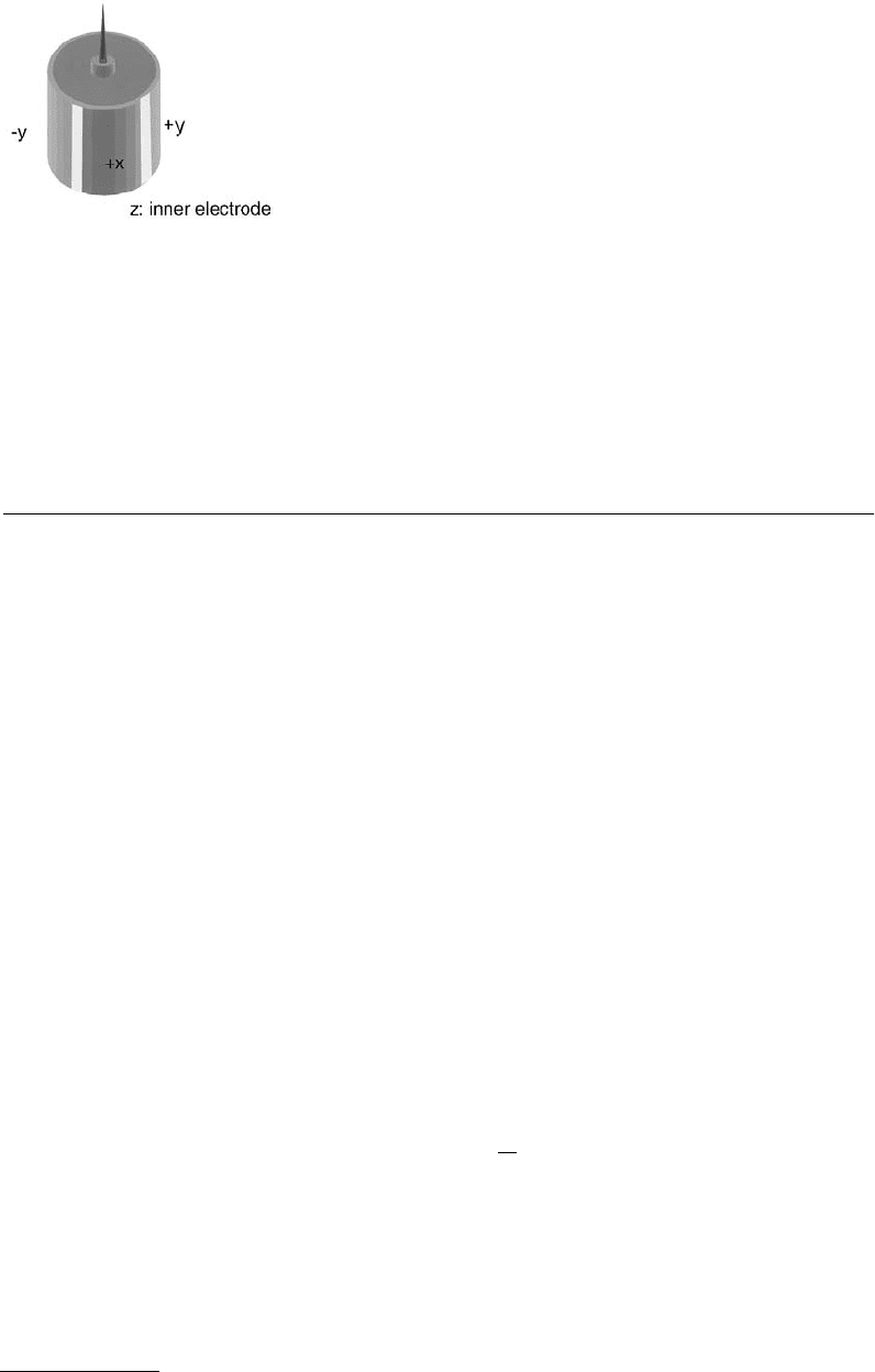
A popular solution is use of tube scanners (Figure 2.18) They are now widely used in SPMs because of
their simplicity and their small size (Binnig and Smith, 1986; Chen, 1992a,b). The outer electrode is
segmented in four equal sectors of 90°. Opposite sectors are driven by signals of the same magnitude,
but opposite sign. This gives, through bending, a two-dimensional movement on, approximately, a sphere.
The inner electrode is normally driven by the z-signal. It is possible, however, to use only the outer
electrodes for scanning and for the z-movement. The main drawback of applying the z-signal to the outer
electrodes is that the applied voltage is the sum of both the x- or y-movement and the z-movement.
Hence, a larger scan size effectively reduces the available range for the z-control.
2.8.2 Piezoeffect
An electric field applied across a piezoelectric material causes a change in the crystal structure, with
expansion in some directions and contraction in others. Also, a net volume change occurs (Ashcroft and
Mermin, 1976). Many SPMs use the transverse piezoelectric effect, where the applied electric field
→
E is
perpendicular to the expansion/contraction direction.
(2.84)
where d
31
is the transverse piezoelectric constant, V the applied voltage, and t the thickness of the piezoslab
or the distance between the electrodes where the voltage is applied.
→
n is the direction of polarization.
Piezotranslators based on the transverse piezoelectric effect have a wide range of sensitivities, limited
mainly by mechanical stability and breakdown voltage.
FIGURE 2.18 Schematic drawing of a piezotube. The piezoceramic is
molded into a tube form. The outer electrode is separated into four segments
and connected to the scanning voltages. The z-voltage is applied to the inner
electrode.
∆ll
r
r
l=⋅
()
=End
V
t
d
31 31
© 1999 by CRC Press LLC
2.8.3 Scan Range
The calculation of the scanning range of a piezotube is difficult (Carr, 1988; Chen, 1992a,b). The bending
of the tube depends on the electric fields and the nonuniform strain induced. A finite-element calculation
where the piezotube was divided into 218 identical elements was used (Carr, 1988) to calculate the
deflection. On each node the mechanical stress, stiffness, strain, and piezoelectric stress were calculated
when a voltage was applied on one electrode. The results were found to be linear on the first iteration,
and higher-order corrections were very small even for large electrode voltages. It was found that to first
order the x- and z-movement of the tube could be reasonably well approximated by assuming that the
piezotube is a segment of a torus. Using this model, one obtains
(2.85)
(2.86)
where |d
31
| is the coefficient of the transversal piezoelectric effect, l is the tube free length, t is the tube
wall thickness, d is the tube diameter, V
+
is the voltage on positive outer electrode while V
–
is the voltage
of the opposite quadrant negative electrode, and V
z
is voltage of inner electrode.
The cantilever or sample mounted on the piezotube has an additional lateral movement because the
point of measurement is not in the end plane of the piezotube. The additional lateral displacement of
the end of the tip is l
S
sin ϕ ≈ l
S
ϕ, where l
S
is the tip length and ϕ is the deflection angle of the end
surface. Assuming that the sample or cantilever is always perpendicular to the end of the walls of the
tube and calculating with the torus model, one gets for the angle
(2.87)
where R is the radius of curvature the piezotube. Using the result of Equation 2.87, one obtains for the
additional x-movement
(2.88)
and for the additional z-movement due to the x-movement
(2.89)
Carr assumed for his finite-element calculations that the top of the tube was completely free to move
and, as a consequence, the top surface was distorted, leading to a deflection angle about half that of the
geometric model. Depending on the attachment of the sample or the cantilever, this distortion may be
smaller, leading to a deflection angle in between that of the geometric model and the one of the finite-
element calculation.
2.8.4 Nonlinearities, Creep
Piezomaterials with a high conversion ratio, i.e., a large d
31
or small electrode separations, with large
scanning ranges are hampered by substantial hysteresis resulting in a deviation from linearity by more
than 10%. The sensitivity of the piezoceramic material (mechanical displacement divided by driving
dx V V d
td
=−
()
+−31
2
2
l
dz V V V d
t
z
=+−
()
+−
2
2
31
2
l
ϕ= = =
l
l
l
lR
dx dx22
2
dx
dx
VVd
td
s
sS
add
== =−
()
+−
l
l
l
ll
ϕ
2
31
dz
dx
VVd
td
SS
S
S
S
add
=− = =
()
=−
()
+−
ll
l
l
l
ll
cos ϕ
ϕ
2
2
2
2
31
2
2
22
2
2
2
© 1999 by CRC Press LLC
voltage) decreases with reduced scanning range, whereas the hysteresis is reduced. A careful selection of
the material for the piezoscanners, the design of the scanners, and of the operating conditions is necessary
to get optimum performance.
2.8.5 Linearization Strategies
2.8.5.1 Passive Linearization: Calculation
The analysis of images affected by piezo nonlinearities (Libioulle et al., 1991; Stoll, 1992; Durselen et al.,
1995; Fu, 1995) shows that the dominant term is
(2.90)
where z is the excursion of the piezo, V the applied voltage, and A and B two coefficients describing the
sensitivity of the material. Equation 2.90 holds for scanning from V = 0 to large V. For the reverse
direction, the equation becomes
(2.91)
where à and
˜
B
are the coefficients for the back scan and V
max
is the applied voltage at the turning point.
Both equations demonstrate that the true x-travel is small at the beginning of the scan and becomes
larger toward the end. Therefore, images are stretched at the beginning and compressed at the end.
Similar equations hold for the slow scan direction. The coefficients, however, are different. The
combined action causes a greatly distorted image. This distortion can be calculated. The data acquisition
systems record the signal as a function of V. However, the data are measured as functions of x. Therefore,
we have to distribute the x-values evenly across the image, which can be done by inverting an approxi-
mation of Equation 2.90. First, we write
(2.92)
For B A, we can approximate
(2.93)
We now substitute Equation 2.93 into the nonlinear term of Equation 2.92. This gives
(2.94)
Hence, an equation of the type
(2.95)
xAVBV=+
2
xAVBVV==−
()
˜˜
max
2
xAV
B
A
V=−
1
V
x
A
=
xAV
Bx
A
V
x
A
Bx A
x
A
Bx
A
=+
=
+
≈−
1
1
1
1
2
22
xx xx
true
with =−
()
=−αβαβ
max
1

© 1999 by CRC Press LLC
takes out the distortion of an image. α and β are dependent on the scan range, the scan speed, and on
the scan history and have to be determined with exactly the same settings as for the measurement. x
max
is the maximal scanning range. The condition for α and β guarantees that the image is transformed onto
itself.
Similar equations as the empirical one shown above Equation 2.95 can be derived by analyzing the
movements of domain walls in piezoceramics.
2.8.5.2 Passive Linearization: Measuring the Position
An alternative strategy is to measure the position of the piezotranslators. Several possibilities exist.
• The interferometers described above can be used to measure the elongation of the piezoelongation.
The fiber-optic interferometer is especially easy to implement. The coherence length of the laser
only limits the measurement range. However, the signal is of periodic nature. Hence, a direct use
of the signal in a feedback circuit for the position is not possible. However, as a measurement tool
and, especially, as a calibration tool the interferometer is without competition. The wavelength of
the light, for instance, in an HeNe laser is so well defined that the precision of the other components
determines the error of the calibration or measurement.
• The movement of the light spot on the quadrant detector can be used to measure the position of
a piezo (Barrett and Quate, 1991). The output current changes by 0.5 A/cm × P [W]/R [cm].
• Typical values (P = 1 mW, R = 0.001 cm) give 0.5 A/cm = 5 × 10
-8
A/nm.
• Again, this means that the laser beam above would have a 0.1-nm noise limitation for a bandwidth
of 21 Hz. The advantage of this method is that, in principle, one can linearize two axes with only
one detector.
• A knife-edge blocking part of a light beam incident on a photodiode can be used to measure the
position of the piezo. This technique, commonly used in optical shear force detection (Betzig et al.,
1992; Toledo-Crow et al., 1992), has a sensitivity of better than 0.1 nm.
• The capacitive detection (Griffith et al., 1990; Holman et al., 1996) of the cantilever deflection can
be applied to the measurement of the piezoelongation. Equations 2.67 to 2.82 apply to the problem.
This technique is commonly used in commercial instruments. The difficulties lie in the avoidance
of fringe effects at the borders of the two plates. While conceptually simple, one needs the latest
technology in surface preparation to get a decent linearity. The electronic circuits used for the
readout are often proprietary.
• Linear variable differential transformers (LVDT) are a convenient means to measure positions
down to 1 nm. They can be used together with a solid-state joint setup, as often used for large
scan range stages. Unlike the capacitive detection, there are few difficulties to implementation.
The sensors and the detection circuits for LVDTs are available commercially.
• A popular measurement technique is use of strain gauges. They are especially sensitive when
mounted on a solid-state joint where the curvature is maximal. The resolution depends mainly
on the induced curvature. A precision of 1 nm is attainable. The signals are low — a Wheatstone
bridge is needed for the readout.
2.8.5.3 Active Linearization
Active linearization is done with feedback systems. Sensors need to be monotonic. Hence, all the systems
described above, with the exception of the interferometers, are suitable. The most common solutions
include the strain gauge approach, the capacitance measurement, or the LVDT, which are all electronic
solutions. Optical detection systems have the disadvantage that the intensity enters into the calibration.
© 1999 by CRC Press LLC
2.8.6 Alternative Scanning Systems
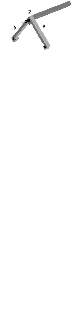
The first STMs were based on piezotripods (Binnig and Rohrer, 1982). The piezotripod (Figure 2.19) is
an intuitive way to generate the three-dimensional movement of a tip attached to its center. However, to
get a suitable stability and scanning range, the tripod needs to be fairly large (about 5 cm). Some
instruments use piezostacks instead of monolithic piezoactuators. They are arranged in the tripod
arrangement. Piezostacks are thin layers of piezoactive materials glued together to form a device with up
to 200 µm of actuation range. Preloading with a suitable metal casing reduces the nonlinearity.
If construction of a home-built scanning system is attempted, using linearized scanning tables is
recommended. They are built around solid-state joints and actuated by piezostacks. The joints guarantee
that the movement is parallel with little deviation from the predefined scanning plane. Because of the
construction, it is easy to add measurement devices such as capacitive sensors, LVDT, or strain gauges,
which are essential for a closed-loop linearization. Two-dimensional tables can be purchased from several
manufacturers. They have a linearity of better than 0.1% and a noise level of 10
–4
to 10
–5
of the maximal
scanning range.
2.8.7 Control Systems
2.8.7.1 Basics
The electronics and software play an important role in the optimal performance of an SPM. Control
electronics and software are supplied nowadays with commercial AFMs. Control electronic systems can
use either analog or digital feedback. While digital feedback offers greater flexibility and ease of config-
uration, analog feedback circuits might be better suited for ultralow noise operation. We will describe
here the basic setups for atomic force microscopy.
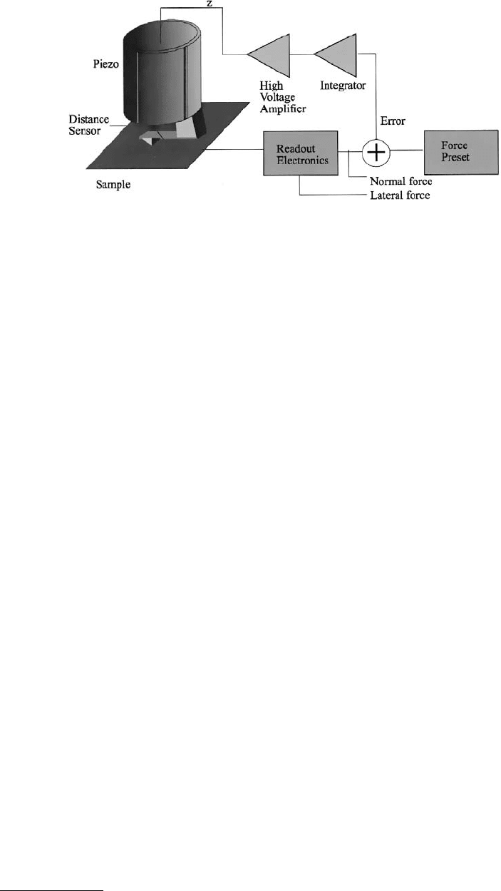
Figure 2.20 shows a block schematic of a typical AFM feedback loop. The signal from the force
transducer is fed into the feedback loop consisting mainly of a subtraction stage to get an error signal
and an integrator. The gain of the integrator (high gain corresponds to short integration times) is set as
high as possible without generating more than 1% overshoot. High gain minimizes the error margin of
the current and forces the tip to follow the contours of constant density of states as well as possible. This
operating mode is known as the “constant-force mode.” A high-voltage amplifier amplifies the outputs
of the integrator. As AFMs using piezotubes usually require ±150 V at the output. The output of the
integrator needs to be amplified by a high-voltage amplifier.
In order to scan the sample, additional voltages at high tension are required to drive the piezo. For
example, with a tube scanner, four scanning voltages are required, namely, +V
x
, –V
x
, +V
y
, and –V
y
. The
x- and y-scanning voltages are generated in a scan generator (analog or computer controlled). Both
voltages are input to the two respective power amplifiers. Two inverting amplifiers generate the input
voltages for the other two power amplifiers. The topography of the sample surface is determined by
recording the input- voltage to the high-voltage amplifier for the z-channel as a function of x and y
(constant-force mode).
FIGURE 2.19 An alternative type of piezoscanners: the tripod.
© 1999 by CRC Press LLC
Another operating mode is the “variable-force mode.” The gain in the feedback loop is lowered and
the scanning speed increased such that the force on the cantilever is no longer constant. Here the force
is recorded as a function of x and y.
2.8.7.2 Force Spectroscopy
Four modes of spectroscopic imaging are in common use with force microscopes: measuring lateral
forces, ∂F/∂z, ∂F/∂x spatially resolved, and measuring force vs. distance curves. Lateral forces can be
measured by detecting the deflection of a cantilever in a direction orthogonal to the normal direction.
The optical lever deflection method does this most easily. Lateral force measurements give indications
of adhesion forces between the tip and the sample.
∂F/∂z measurements probe the local elasticity of the sample surface. In many cases the measured
quantity originates from a volume of a few cubic nanometers. The ∂F/∂z, or local stiffness signal, is
proportional to Young’s modulus, as far as one can define this quantity. Local stiffness is measured by
vibrating the cantilever by a small amount in the z-direction. The expected signal for very stiff samples
is zero; for very soft samples one also gets, independent of the stiffness, a constant signal. This signal is
again zero for the optical lever deflection and equal to the driving amplitude for interferometric mea-
surements. The best sensitivity is obtained when the compliance of the cantilever matches the stiffness
of the sample.
A third spectroscopic quantity is the lateral stiffness. It is measured by applying a small modulation
in the x-direction on the cantilever. The signal is again optimal when the lateral compliance of the
cantilever matches the lateral stiffness of the sample. The lateral stiffness is, in turn, related to the shear
modulus of the sample.
Detailed information on the interaction of the tip and the sample can be gained by measuring force
vs. distance curves. It is necessary to have cantilevers with high enough compliance to avoid instabilities
due to the attractive forces on the sample.
2.8.7.3 Using the Control Electronics as a Two-Dimensional Measurement Tool
Usually, the control electronics of an AFM is used to control the x- and y-piezosignals while several data
acquisition channels record the position-dependent signals. The control electronics can be used in another
way: it can be viewed as a two-dimensional function generator. What is normally the x- and y-signal can
be used to control two independent variables of an experiment. The control logic of the AFM then ensures
that the available parameter space is systematically probed at equally spaced points.
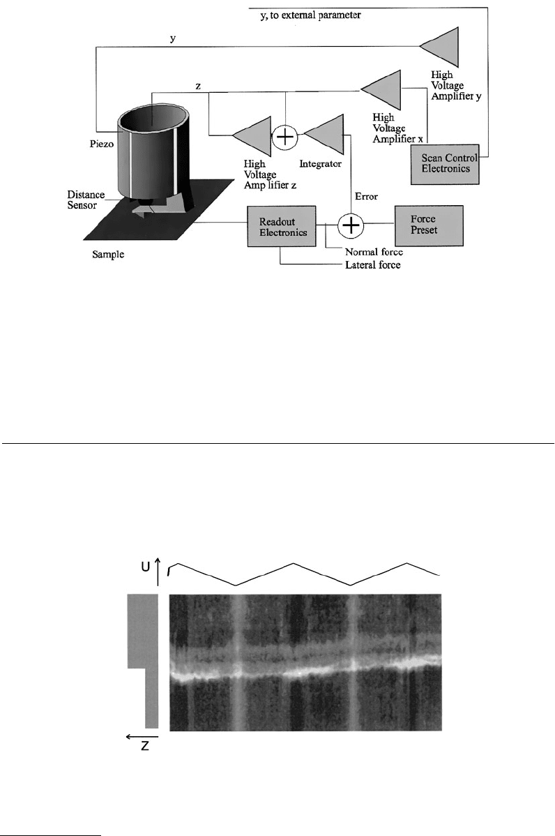
2.8.7.3.1 Friction Force Curves on a Line
An example is a friction force curve measured along a line across a step on graphite. Figure 2.21 shows
the connections. The z-piezo is connected as usual, like the x-piezo. However, the y-output is used to
command the electrochemical potential.
FIGURE 2.20 Block schematics of the feedback control loop of AFMs.
© 1999 by CRC Press LLC
The offset of the y-channel determines the position of the tip on the sample surface, together with the
x-channel. Figure 2.22 shows a typical result. The image shows the lateral force on one scan line across
a step on highly pyrolytic graphite (HOPG), as a function of the applied electrochemical potential. A
discussion of this result can be found in the literature (Binggeli et al., 1993; Weilandt et al., 1995a,b).
2.9 AFMs
2.9.1 Special Design Considerations
The size of an AFM is typically of the order of several centimeters. To illustrate the problem of thermal
drift, we calculate the requirements on the temperature stability for a microscope working with repulsive
forces and which does not employ heterodyne detection. If we assume a cantilever spring with a 1 N/m
FIGURE 2.21 Wiring of an AFM to measure friction force curves along a line.
FIGURE 2.22 Friction measurement curve along a sample line. Bright colors encode high lateral forces. Friction
was modified by changing the applied potential.

© 1999 by CRC Press LLC
spring constant and if we set the force to 10
–8
N, then the static deflection of the cantilever is 10 nm. The
typical size of a tunneling force detector is 1-cm length from the tunnel junction to the common
attachment plane. A design with well-compensated thermal expansion coefficients will have a remaining
thermal expansion coefficient of 10
–6
1/K. This means that keeping the force within 10% requires a
thermal stability of the microscope of 0.1 K. In less well compensated design, the allowable temperature
fluctuations might be as low as 0.01 K.
If the temperature stability of the setup is not sufficient, one can either use larger static deflections,
which means larger forces, or a softer cantilever spring, which means degraded frequency response. For
measurements with the smallest possible forces, a careful design of the force sensor with respect to thermal
drift is a prerequisite.
The classical Michelson or Mach–Zehnder interferometers have the worst temperature drift, since their
relevant distances for differential thermal expansions may be more than 10 cm long. The fiber-optic
interferometer is comparable to the tunneling detector in its thermal performance, since the distances
needed to position the end of the fiber are of order 1 cm. Much better is the Nomarski detector for the
cantilever deflection. This detector is only sensitive to a thermally induced rotation of the cantilever
spring. A crude estimate gives relevant distances for the thermal expansion of a few 10 mm. This increases
the allowable temperature variations to more than 1 K.
Equally well suited is the optical lever method. This method is, to first order, only sensitive to the tilt
of the reflecting mirror. For small angles between the incident and the reflected light beam, the change
in distance between the plane defined by the quadrant detector and the light source is negligible. Any
distance change between the light source and the quadrant detector directly affects the output signal.
However, the deflection of the cantilever is amplified by a factor of up to 1000 due to the geometric
amplification. Hence, the optical lever method is, to first order, insensitive to thermal drift.
2.9.2 Classical Setup
Scanning tunneling microscopes are almost exclusively built according to one principle: the tunneling
tip is mounted on some translation stage and scanned past the sample. The reason for this is twofold.
First, most STMs were built for ultrahigh vacuum operation, where it is of paramount importance that
the sample can be exchanged. Since piezos are rather fragile, it was the natural choice to scan the tip.
The second reason is that the tip is lighter than the sample. As one can deduce from the equations
describing cantilevers, reduced masses mean increased resonance frequency and hence increased scanning
speed. By following these rules, AFMs were built with scanned samples. Most AFMs operate at ambient
conditions. The force detection mechanism is bulky; especially after the implementation of the optical
lever (Meyer and Amer, 1988; Alexander et al., 1989), where the detection unit is of the size of several
centimeters, microscope designers preferred to scan the sample instead of the sensor..
Figure 2.23 shows an example of such a microscope. It consists of two parts, the base and force sensor
head. The base houses the scanning piezo, the motor driving the approach screw, and the sample. All
connectors from the control unit to the microscope end here. The base acts as an additional vibration
damper, shielding the sensitive parts from the environment. The force sensor head includes the cantilever,
a laser diode with suitable optics, and a position-sensitive detector. The preamplifier for this detector is
often located on the head. This minimizes the stray capacitance and hence the noise and maximizes the
bandwidth. The microscope shown in Figure 2.23 relies on external vibration damping. Common means
are an air-cushioned table or a concrete platform suspended by bungee cords.
If one is not satisfied with the scan range or the linearity of a microscope, then there is the possibility
to replace the base by a commercial linearized scanning table. The geometry is the same; all that is needed
is to adapt the support and the approach system of the force-sensing head.
AFMs operating in air usually have their vibration damping system built-in. Figure 2.25 shows the
multimode ultrahigh vacuum SPM of Omicron (Omicron; Howald et al., 1993). The instrument is based
on the optical lever principle (see Figure 2.24). The light beam coming from the laser diode is directed
by a mirror mounted on a piezomotor with two tilt directions to the cantilever. The reflected light is
© 1999 by CRC Press LLC
steered onto the quadrant detector by another mirror mounted on a piezomotor. The piezomotors are
essential for the design because it is not possible to have an adjustment from the exterior side in the
ultrahigh vacuum.
The optics shown in Figure 2.24 is mounted on a vibration isolation platform, as can be seen in
Figure 2.25. The three pillars house a spring each. The microscope platform is supported by these springs.
Damping is provided by the magnetic eddy current brakes, shown at the rim of the instrument.
The microscope in Figure 2.25 is capable of imaging delicate samples such as the silicon (111) surface
at atomic resolution in noncontact mode. Figure 2.26 is an example of such a measurement. The reso-
lution is proved by the fact that defects are visible.
FIGURE 2.23 An example of the basic AFM setup.
FIGURE 2.24 Setup of the Omicron ultrahigh vacuum AFM. (Courtesy of Omicron. Used with permission.)