Caers J. Modeling Uncertainty in the Earth Sciences
Подождите немного. Документ загружается.

P1: OTA/XYZ P2: ABC
JWST061-05 JWST061-Caers March 29, 2011 9:6 Printer Name: Yet to Come
5.2 THE VARIOGRAM 81
r(Δt)
r(Δt)
1
0.8
0.6
0.4
0.2
-0.2
-0.4
0
0102030
Time interval Δt
40 50
r(Δt)
1
0.8
0.6
0.4
0.2
-0.2
-0.4
0
01020304050
1
0.8
0.6
0.4
0.2
-0.2
-0.4
0
01020304050
r(Δt)
1
0.8
0.6
0.4
0.2
-0.2
-0.4
0
0 1020 304050
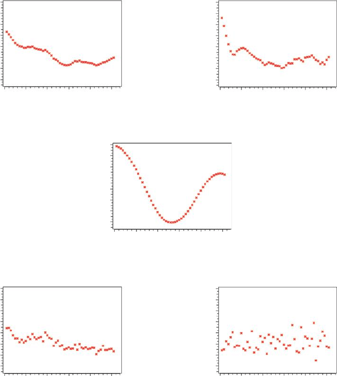
Case 1
r(Δt)
1
0.8
0.6
0.4
0.2
-0.2
-0.4
0
0102030
Time interval Δt
Time interval Δt
Time interval Δt Time interval Δt
40 50
Case 2
Case 3
Case 4 Case 5
Figure 5.2 (Continued)
units. This length is termed the correlation length. In Case 2 the correlation length is
approximately 10 units. In Case 3 periodicity of the time series, which is also present in
the correlogram, is observed. In Case 4 discontinuity for small distance t (the correla-
tion drops from unity rapidly to 0.4) is observed; this usually means that there is either a
measurement error or a small variation that the sampling did not detect. Case 5 shows
perfectly uncorrelated time events, hence the correlogram fluctuates around zero for
all intervals.

P1: OTA/XYZ P2: ABC
JWST061-05 JWST061-Caers March 29, 2011 9:6 Printer Name: Yet to Come
82 CH 5 MODELING SPATIAL CONTINUITY
5.2.2 Autocorrelation in 2D and 3D
In the previous section, we concentrated on calculating autocorrelation functions in 1D
(i.e., time series). It was seen that autocorrelations somehow quantify the type and extent
of dependency between basic instances in time. This idea can be extended to phenomena
occurring in the 2D plane or in 3D space.
Suppose samples are collected on a regular grid. The main difference in calculating
autocorrelation in 2D space is that now it is necessary to look at various directions.
In 1D, there is only one direction. In 2D, there are an infinite number of directions.
Directions are important, because spatial phenomena are often oriented according to a
preferential direction.
In order to calculate the autocorrelation, it is first necessary to specify a particular lag
spacing and direction (Figure 5.3).
Then, one proceeds the same way as done in 1D. Pairs of observations are col-
lected that are a specific lag distance and direction away and gathered in a scatter plot
(Figure 5.3). Next, this is repeated for the same direction but for different lag distance.
All correlation coefficient values calculated this way are plotted on a plot of r versus lag
distance for a particular direction, as shown in Figure 5.3. This procedure is then repeated
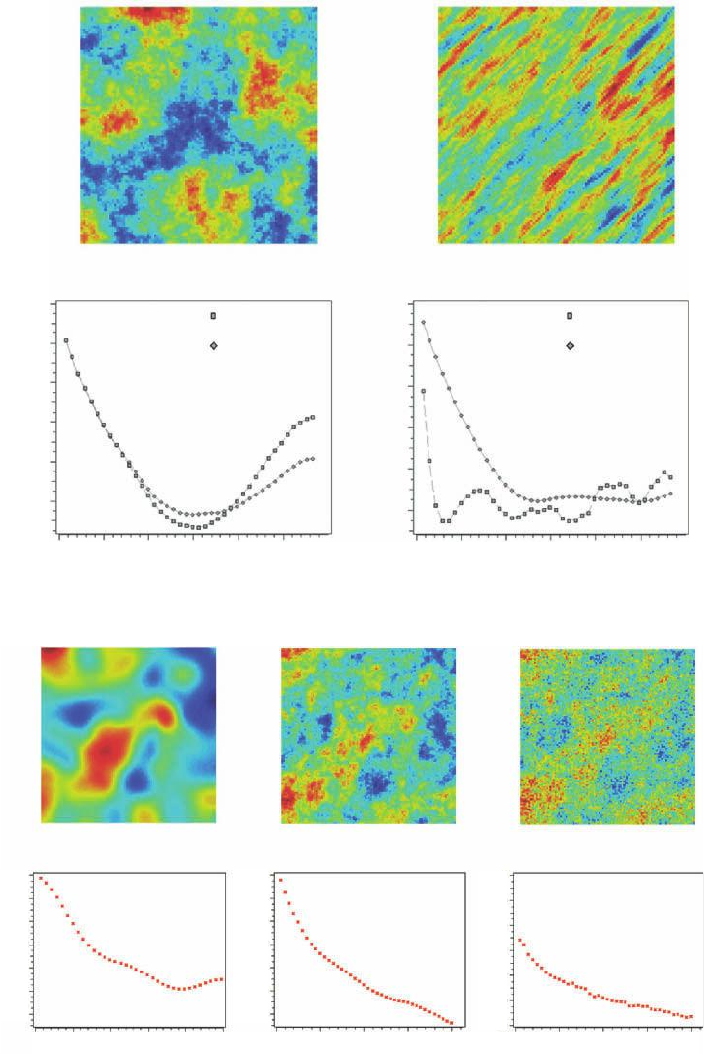
for several directions, , resulting in an autocorrelation plot for each direction. Some 2D
examples are shown in Figure 5.4. Cases 1 and 2 show the impact of the anisotropy on the
direcon θ
scaer plot for direcon θ
and lag-spacing |h|
1
autocorrelaon for
direcon θ
r(
|
h
|)
La
g
distance |h|
y(u)
y(u
+h)
y(u)
y(u
+h)
lag vector h
Figure 5.3 Direction and lag-spacing between two samples on a regular grid, corresponding
scatter plot and construction of the correlogram or autocorrelation plot for that direction. u is a
coordinate in space.
P1: OTA/XYZ P2: ABC
JWST061-05 JWST061-Caers March 29, 2011 9:6 Printer Name: Yet to Come
5.2 THE VARIOGRAM 83
Case 1
NW direcon
NE direcon
r(h)
1
0.8
0.6
0.4
0.2
0
0102030
Distance h
40 50
r(h)
1
0.8
0.6
0.4
0.2
0
0102030
Distance h
40 50
NW direcon
NE direcon
Case 2
(a)
r(h)
1
0.8
0.6
0.4
0.2
0
-0.2
0102030
Distance h
40 50
r(h)
1
0.8
0.6
0.4
0.2
0
-0.2
0102030
Distance h
40
r(h)
1
0.8
0.6
0.4
0.2
0
-0.2
0102030
Distance h
40
Case 3 Case 4 Case 5
Figure 5.4 (a) Example cases of 2D autocorrelation functions; (b) example cases of 2D autocor-
relation functions.
P1: OTA/XYZ P2: ABC
JWST061-05 JWST061-Caers March 29, 2011 9:6 Printer Name: Yet to Come
84 CH 5 MODELING SPATIAL CONTINUITY
calculation of the correlogram for various directions. Case 3 has very smoothly varying
spatial variation resulting in a slow drop of the correlogram for small distances h. Case 4
has less smooth spatial variability, while case 5 contains a sudden drop of correlation for
small distance resulting in a more noisy image.
5.2.3 The Variogram and Covariance Function
While the empirical correlation function is a perfect way to characterize the spatial or
temporal degree of correlation between events distributed in space or time, it is not the
traditional way to do so in the Earth and Environmental Sciences or in geostatistics. In
geostatistics, one prefers working with the variogram instead (Figure 5.5). The reason
why this is preferred is discussed later.
Consider studying a variable Z varying in space and/or time. In that regard a coor-
dinate u = (x,y,z)oru = (x,y,z,t) is also attached to it. In notation of expected value
(as if there is an infinite sample of Z) introduced in Chapter 2, the autocorrelation
function equals
(h) =
E
[
(Z (u) − m)(Z(u + h) − m)
]
Var ( Z )
with m = E
[
Z(u + h)
]
= E
[
Z(u)
]
with h some vector with a given lag-spacing and direction as shown in Figures 5.2 and
5.3. Before discussing the variogram, we will introduce a measure of correlation very
similar to the autocorrelation function, termed the covariance function. Recall that, no
matter what the data is, one always start at (h) = 1for|h|=0. For the covariance
function, C(h), one starts at C(h) = Va r(Z)for|h|=0. Basically, (h) is multiplied with
the variance of the variable:
C(h) = E
[
(Z (u) − m)(Z(u + h) − m)
]
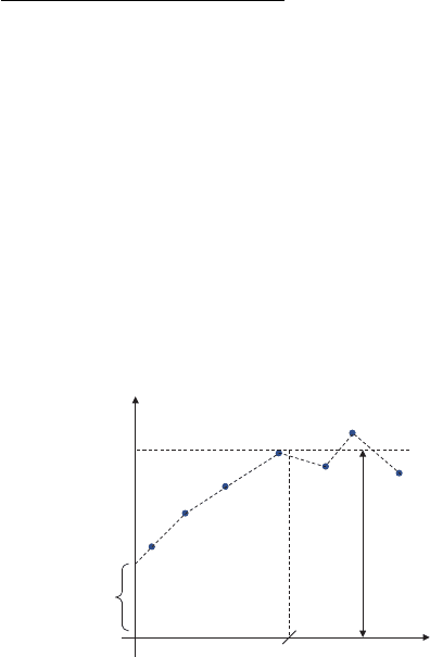
Sill
Range
Var
(
X)
h
Experimenta
l
variogram
Nugget
Figure 5.5 Elements of an experimental variogram.

P1: OTA/XYZ P2: ABC
JWST061-05 JWST061-Caers March 29, 2011 9:6 Printer Name: Yet to Come
5.2 THE VARIOGRAM 85
Variogram
γ
γ
(h)
Varianc
e
of
Z
Fli
p
th
e
funcon
Autocorrelao
n
funcon
ρ
(h)
1
Distance
Mulply
wit
h
variance
Covarianc
e
funcon
C(h)
Varianc
e
of
Z
Distance Distance
Figure 5.6 Relationship between autocorrelation, covariance and variogram functions.
While the autocorrelation function does not contain any information on the variance
of the phenomenon under investigation, the covariance function does. Finally, the (semi)-
variogram
1
is defined as
␥
(
h
)
= Var( Z) − C
(
h
)
which is equivalent to
␥
(
h
)
=
1
2
E
(
Z(u) − Z (u + h)
)
2
One might wonder what this is all good for. After all, we first did a simple multipli-
cation and then flipped the function (Figure 5.6). Suppose, for example, that the variance
is really large; in fact it gets larger as more data are gathered over an increasingly larger
area (it may be an indication that the variance is not very well defined). In that case, the
covariance function, which starts at the variance, would become unstable, it continuously
changes. The variogram does not have this problem. It would simply start at zero for
1
Variogram and (semi)-variogram are often used intertwined, although the latter is half the former.

P1: OTA/XYZ P2: ABC
JWST061-05 JWST061-Caers March 29, 2011 9:6 Printer Name: Yet to Come
86 CH 5 MODELING SPATIAL CONTINUITY
h = 0, and then will keep increasing. Note that the equation for the variogram does not
call for the calculation of a mean or variance because it can simply be estimated from a
limited sample as
estimate of ␥(h) =
1
2n(h)
all u
(
z(u) − z(u + h)
)
2
with n(h) the number of pairs found for that lag h.
5.2.4 Variogram Analysis
In this section, the most important features of correlograms or variograms are outlined. In
reality however, such analysis is not easy as it seems on paper since data may be “noisy”,
that is, there are errors in the data or there may simply not be enough data.
In general, but not necessarily in all cases, the following important features can be
determined from a variogram estimate (Figure 5.5):
r
Range: as the separation distance h increases, less correlation is expected, and hence
an increase in the variogram. At some point, this increase flattens off and a plateau is
reached. The distance h where this plateau is reached is termed the range.
r
Sill: the level of this plateau is termed the sill, and it is often equal to the variance of
the sample values.
r
Nugget Effect: by definition, the variogram value at h = 0 is exactly zero. However, for
small h, a sudden jump in the variogram value is often observed. This jump is termed
the nugget effect.
This nugget effect is often due to small scale variability that is not sampled because the
distance between the samples is too large. Historically, the term refers to the small scale
variability that is caused in gold mines when a sample contains a gold nugget (a very
short scale variation of gold grade). Another reason for a nugget effect is error (noise)
in the measurements. If these errors act like random noise, then a nugget effect will be
observed.
5.2.4.1 Anisotropy
We showed earlier that the range (correlation length) can vary according to the direction
in which the variogram is calculated. This makes sense since the Earth may vary differ-
ently in different directions. For example, layers in the Earth are more continuous in the
horizontal direction than in the vertical direction.
5.2.4.2 What is the Practical Meaning of a Variogram?
A variogram measures the geological distance between any two points in space. Recall
that a Euclidean distance simply measures the distance between any two locations in a
Cartesian space.
P1: OTA/XYZ P2: ABC
JWST061-05 JWST061-Caers March 29, 2011 9:6 Printer Name: Yet to Come
5.3 THE BOOLEAN OR OBJECT MODEL 87
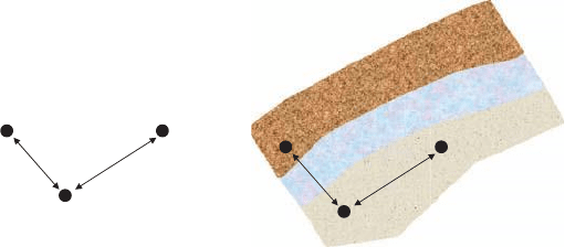
3
1
2
h
13
h
12
3
1
2
h
13
h
12
Layered system
Distance between 3 locaons
Figure 5.7 A variogram distance versus a Euclidean distance.
Figure 5.7 explains the difference between Euclidean and “geological” distance: sup-
pose the geology of a region is layered, then it appears that there is clear anisotropy in the
45
◦
diagonal direction. Hence, samples 1 and 2 can, at least geologically, be considered
as more similar (hence closer) than samples 1 and 3. This degree of similarity is measured
by the variogram. It would be expected that:
␥
(
h
13
)
> ␥
(
h
12
)
even though h
12
> h
13
.
5.2.5 A Word on Variogram Modeling
Simply calculating the variogram in 1, 2 or 3D is not enough, it is necessary to provide
a “model”, just like a set of numbers is not a model pdf, it is only an empirical pdf; it
is necessary to complete the pdf by interpolation and extrapolation rules as outlined in
Chapter 2. Variogram modeling is not trivial since there are some more restrictions on
what can be done, but the idea is the same: interpolation of the calculated variogram
with a smooth curve. This topic is for more advanced geostatistics books and this work
is typically carried out by geostatisticians. Throughout the further chapters it is assumed
that such a model is available, that is, that we can evaluate the variogram for any lag
distance and direction.
5.3 The Boolean or Object Model
5.3.1 Motivation
Variograms are crude descriptions of actual spatial phenomena. Since the variogram cap-
tures spatial continuity by considering sample values taken two at a time, it cannot capture
well complex spatial phenomena, such as shown in Figure 5.8 and 5.9. Indeed, a nugget
value, a range (or set of ranges per direction) and a sill could not describe the complex
sinuous variation of a channel or the growth of carbonate mounds and reefs that may need
hundreds of parameters for a complete description.
Since all cases in Figure 5.9 are actual naturally occurring systems, subject to physical
laws, one idea is to simply “simulate” the genesis (deposition, growth, evolution) of these
P1: OTA/XYZ P2: ABC
JWST061-05 JWST061-Caers March 29, 2011 9:6 Printer Name: Yet to Come
88 CH 5 MODELING SPATIAL CONTINUITY
Real Simulated
Figure 5.8 A real phenomena versus a process simulation of it.
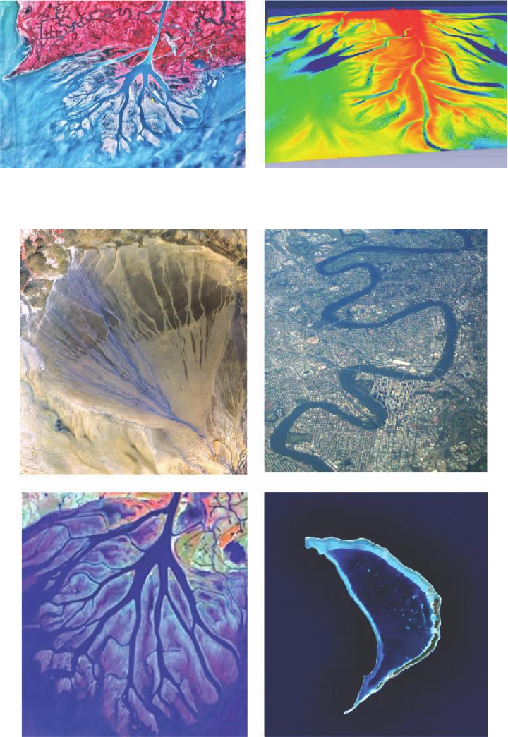
Figure 5.9 An alluvial fan (top left), a meandering river (top right), a delta (bottom left), an
atol (bottom right).

P1: OTA/XYZ P2: ABC
JWST061-05 JWST061-Caers March 29, 2011 9:6 Printer Name: Yet to Come
5.3 THE BOOLEAN OR OBJECT MODEL 89
systems on a computer. For example, it is possible to simulate how a delta dumps sand and
silt material over the delta plain by looking at rules of deposition and erosion coupled with
physical laws of turbulent fluid flow. Figure 5.8 gives an example. In geological modeling
these models are often termed “process” models.
However, such process simulation may need days, sometimes weeks of computation
time. Referring to the discussion in Chapter 3 on deterministic models, such models may
be physically realistic but may not have much quantitative prediction power for two rea-
sons: (1) they do not reflect uncertainty about the phenomena, (2) they may be hard to
calibrate to data, particularly in subsurface modeling where data from wells and geophys-
ical surveys are available. However, the result of a process model may provide a wealth
of information about the style of spatial variation, the architecture of sediments and so
on. Such information can be used by simpler, nonphysical models to mimic, not through
actual simulation of processes but through stochastic simulation, the style of spatial con-
tinuity present. One such model is the Boolean model. If spatial continuity presents itself
through objects, then a Boolean model describes the geometry, dimension and interaction
of these objects. A Boolean Earth model is then an actual representation of this model
description in 3D. Figure 5.10 shows that a Boolean Earth model can mimic fairly well
the style of spatial continuity observed in a process model.
5.3.2 Object Models
Object models (also termed “Boolean models”) were introduced to overcome some of
the limitations of the variogram-based tools by importing realistic shapes and associations
into a model. Crisp curvilinear shapes are often hard to model with cell-based techniques.
The object simulation approach consists of dropping directly onto the grid a set of objects
Proces
s
-
based
simulaon Boolean
or
object
simulaon
Week
s
to
simulate Seconds
to
simulate
Figure 5.10 A process model versus a simulation of a Boolean model.
P1: OTA/XYZ P2: ABC
JWST061-05 JWST061-Caers March 29, 2011 9:6 Printer Name: Yet to Come
90 CH 5 MODELING SPATIAL CONTINUITY
representing different categories (rock types, sedimentary facies, and fractures). These
objects are then moved around to match the data by Markov chain simulation, which
is discussed in Chapter 6. This technique has mostly been used to model sedimentary
objects in reservoirs or aquifers, but many other applications can be envisioned, such as
for example the simulation of gold veins.
Before “simulating” the objects, it is necessary to define the object model. The first task
is to establish the various types of objects (sinuous, elliptic, cubic) and their dimensions
(width, thickness or width to thickness ratio, vertical cross section parameters, sinuosity,
etc.) which can be constant or varying according to a user specified distribution function.
Next it is necessary to specify their mutual spatial relationship: erosion of one object by
another, embedding, and attraction/repulsion of objects.
For example, in the case of channel type system (fluvial or submarine) various sources
of information can be considered to define the object model:
r
Outcrop studies of analog systems are probably the best source of information, although
there is a possibility of bias that comes up when inferring 3D object properties from 2D
outcrops (smaller 3D objects are less likely to occur in 2D sections).
r
Data from the site itself may provide information on object geometry, or may at least
help in relating object shape parameters from outcrop data to the objects shapes being
simulated.
5.4 3D Training Image Models
In many cases, it is not possible to capture spatial complexity by a few variogram pa-
rameters or even by a limited set of object shapes. The 3D training image approach is
a relatively new tool for modelers to communicate the spatial continuity style, explicitly
as a full 3D image, not as a set of parameters, whether variogram ranges or distributions
of object dimensions. The 3D training image is not an Earth model; it is a conceptual
rendering of the major variations that may exist in the studied area. The aim is then to
build 3D Earth models that mimic the spatial continuity of the 3D training image, and
at the same time constrain such Earth model to data. This topic is covered in the next
chapter. In this way the training image is much like a “texture mapping” approach used
in the games industry. A particular pattern is presented, such as in Figure 5.11, then the
trick is to randomize this pattern over the area being modeled. In the Earth Sciences this
must be done in 3D as well as be constrained to data.
Training images may be defined at various scales, from the large 10–100 km basin
scale to the m pore scale. Figure 5.12 shows a training image of a reservoir potential
consisting of channel sand with overbank deposits next to a binary training image of pores
in a sandstone matrix.
Often, many alternative training images are created, reflecting uncertainty about
the understanding of the studied phenomenon. This issue is considered extensively in
Chapters 9 and 10.