Canete J.F. System Engineering and Automation: An Interactive Educational Approach
Подождите немного. Документ загружается.


18 2 System Modeling
The linkage between effort and displacement variables defines the capacitive
element, generally a non-linear relationship, which in the linear case defines the
capacitance parameter C that characterizes the dynamic property of this element.
table 2.2 defines the general nonlinear relationship both in direct and inverse form,
the linear relationship and the dimension of capacitance for electrical systems,
mechanical displacement and rotation systems, hydraulic systems, and thermal
systems.
Finally, the linkage between effort and momentum variables defines, the inertia
element, generally a non-linear relationship, which in the linear case, defines
the inertia parameter I that characterizes the dynamic property of this element.
table 2.3 defines the general nonlinear relationship both in direct and inverse form,
the linear relationship and the dimension of capacitance for electrical systems,
mechanical displacement and rotation systems, hydraulic systems, and thermal
systems.
Table 2.3 Inertia element’s relations between generalized variables.
General
Relation
Linear
Relation
Generalized Variables
Electrical
Mechanical Translation
Mechanical Rotation
Hydraulic
Thermal
In order to obtain the dynamic equations corresponding to these physical
systems, conservation laws are applied involving the elements above described.
Basically, the values of the variables effort of interrelated elements that form a
loop is zero and the sum of the flow variables at a node of interconnection is also
zero (fig. 2.5).
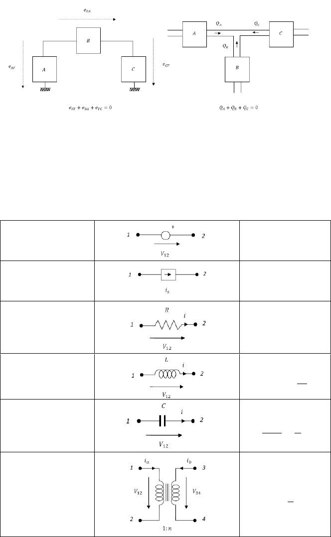
2.3 Electrical Systems 19
Fig. 2.5 Conservation laws used for dynamic equations of system models
2.3 Electrical Systems
In order to derive the mathematical model of electric systems, we will deal only
with lumped systems made up of combinations of ideal electrical elements.
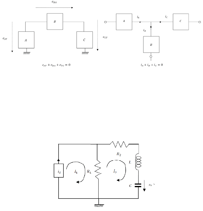
Table 2.4 Electrical elements and corresponding dynamic equations
Voltage
Source
Current
Source
Resistor
Inductor
Capacitor
1
Transformer
·
1
20 2 System Modeling
Most elements to be considered are two-terminal elements, characterized by the
voltage and current, as effort and flow variables respectively.
In table 2.4 the main elements that appear at electrical circuits with its
corresponding icons and dynamic equations are described.
The Kirchoff laws are employed to obtain a complete set of equations involving
the electrical elements as they are connected to form the electrical system. The
Kirchoff’s voltage law settles that the sum of voltage that drops around a loop
must be equal to zero, while the current law states that the sum of the currents at a
node must be also zero (fig. 2.6).
Fig. 2.6 Conservation laws used to obtain the dynamic equations for electrical systems.
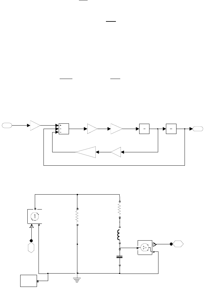
Example 2.1
Derive the dynamic equations corresponding to the circuit shown in fig. 2.7 with
i
s
(t) and v
o
(t) considered as input and output of the system respectively, also
drawing the corresponding SIMULINK and SIMSCAPE modeling diagrams.
Fig. 2.7 Electric system for example 2.1
2.3 Electrical Systems 21
Solution
0
Solving for
and substituting
into the first equation yields
In fig. 2.8 and fig. 2.9 the corresponding modeling diagram developed by using
both the SIMULINK and SIMSCAPE environments are shown.
Fig. 2.8 SIMULINK diagram corresponding to example 2.1
Fig. 2.9 SIMSCAPE diagram corresponding to example 2.1
vo
1
Subtract
Integrator 1
1
s
Integrator
1
s
Gain 4
R1+R2
Gain 3
C
Gain 2
1/C
Gain 1
1/L
Gain
R1
is
1
is
ddvo dvo vo
v0
2
is 1
+
V
-
Solver
f(x)=0
R2
+
-
R1
+
-
L
+
-
Ground
C
+
-
22 2 System Modeling
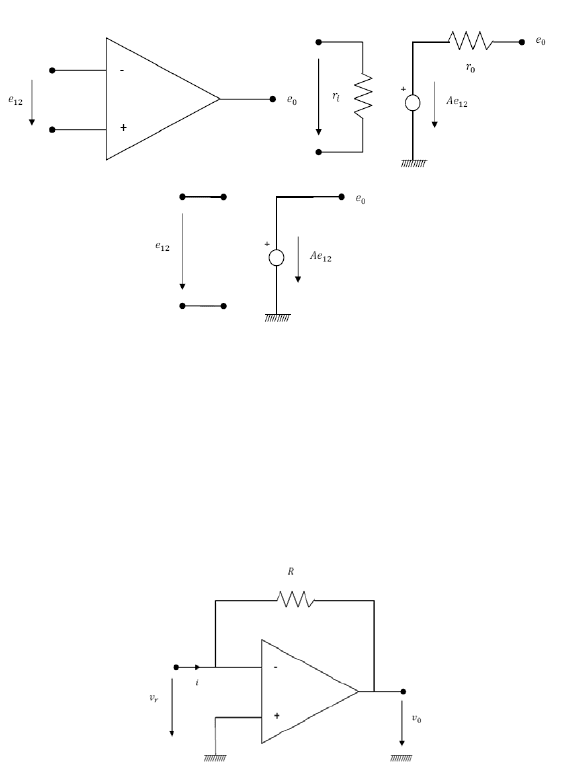
Some important types of electric elements have more than two terminals, as is
the case of the operational amplifier (OA), with two input terminals and one
output terminal. This element’s behavior can be approximated by an ideal
equivalent circuit (fig. 2.10).
Fig. 2.10 Operational amplifier and equivalent circuit
Normally, the ideal operational amplifier is used in practice with feedback in
order to stabilize it, from the start to the inverting terminal (fig. 2.11). Thus,
assuming a zero voltage drop between inverting and non inverting terminals,
we have
Fig. 2.11 Operational amplifier with feedback loop
Example 2.2
Derive the dynamic equations corresponding to the circuit with OA shown in
fig. 2.12 with e
i
(t) and e
o
(t) considered as input and output of the system
respectively, also drawing the corresponding SIMULINK and SIMSCAPE
modeling diagrams.
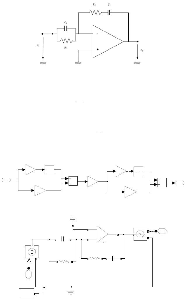
2.3 Electrical Systems 23
Fig. 2.12 Electric system for example 2.2
Solution
1
1
In fig. 2.13 and fig. 2.14 the corresponding modeling diagram developed by using
both the SIMULINK and SIMSCAPE environments are shown.
Fig. 2.13 SIMULINK diagram corresponding to example 2.2
Fig. 2.14 SIMSCAPE diagram corresponding to example 2.2
eo
eo
1
Integrator
1
s
Gain 4
-K -
Gain 3
R2
Gain 2
-1
Gain 1
C1
Gain
1/R1
Derivat ive
du /dt
Add1
Add
ei
1
ei
i11
i12
i1 i2
e0
2
ei
1
+
V
-
ground
Solver
f(x)=0
R2
+
-
R1
+
-
Op-Amp
+
-
C2
+
-
C1
+
-
24 2 System Modeling
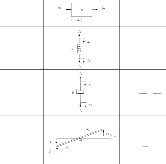
2.4 Mechanical Systems
In order to obtain the dynamic equations governing the mechanical systems, we
deal firstly with the translational mechanical systems, and secondly with the
mechanical rotational systems. Again, we will deal only with lumped systems
made up of combinations of ideal mechanical elements.
In table 2.5 the main elements that appear at translational mechanical systems
with its corresponding icons and dynamic equations are described.
Table 2.5 Translational mechanical elements and corresponding dynamic equations
Mass
Translational
Spring
Translational
Damper
Lever
The D’Alambert law is applied to get the dynamic equations corresponding to
the translational mechanical systems. This is just a restatement of the second law
of Newton, described by
2.4 Mechanical Systems 25
(2.1)
where the summation includes all the external forces applied to the mass M. Then,
by considering the term
as the inertial force, it results in the
translational D’Alambert law given by
0
(2.2)
The dynamic equations are obtained by applying the D’Alembert law to each
mass, using the free-body diagram showing all external forces and the inertial
force with corresponding senses, once the positive sense has been previously
defined.
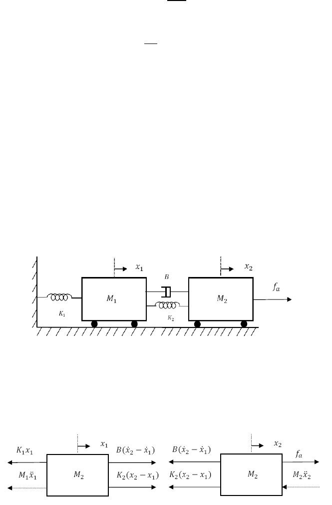
Example 2.3
Derive the dynamic equations corresponding to the translational mechanical
system shown in fig. 2.15, with fa(t) and x1(t) with x2(t) considered as input and
output of the system respectively, also drawing the corresponding SIMULINK and
SIMSCAPE modeling diagrams.
Fig. 2.15 Translational mechanical system for example 2.3
Solution
Firstly, we draw the free-body diagram for each mass (fig. 2.16)
Fig. 2.16 Free-body diagrams for example 2.3
26 2 System Modeling
0
0
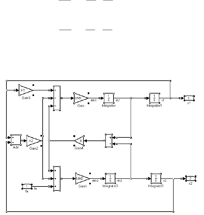
In fig. 2.17 and fig. 2.18 the corresponding modeling diagram developed by using
both the SIMULINK and SIMSCAPE environments are shown.
Fig. 2.17 SIMULINK diagram corresponding to example 2.3
The modeling of rotational mechanical systems follow a similar approach to the
one discussed for translational mechanical systems.
In table 2.6 the main elements that appear at rotational mechanical systems with
its corresponding icons and dynamic equations are described.
2.4 Mechanical Systems 27
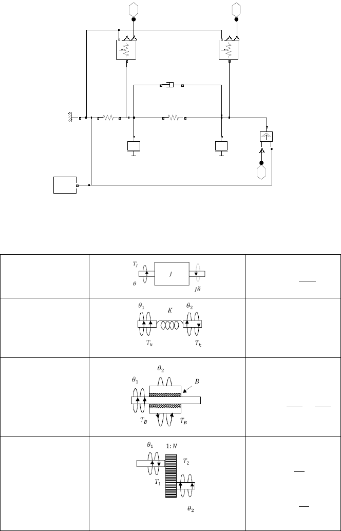
Fig. 2.18 SIMSCAPE diagram corresponding to example 2.3
Table 2.6 Rotational mechanical elements and corresponding dynamic equations
Inertia
Rotational
Spring
Rotational
Damper
Gear
x1 3 x2 2
fa 1
ground
Solver
f(x)=0
M2M1
K2
R
C
K1
R
C
B
R
C
S
C
R
R
C
V
P
R
C
V
P