Canete J.F. System Engineering and Automation: An Interactive Educational Approach
Подождите немного. Документ загружается.


Appendix D:
The SIMSCAPE Modeling Environment
Tutorial
Appe ndix DThe SI MSCA PE Mo deli ng E nvi ron ment Tuto ria l
Appendix D
D.1 Introduction
SIMSCAPE is a MATLAB-based, object-oriented physical modeling language
that enables the user to create models of physical components using an acausal
modeling approach.
This language is designed for use in the MATLAB and SIMULINK environments,
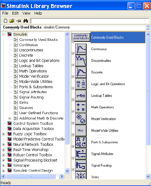
for it can benefit MATLAB functions and SIMULINK blocks (fig. D.1).
Fig. D.1 The SIMULINK Library browser
240 Appendix D: The SIMSCAPE Modeling Environment Tutorial
The integration of control systems with physical systems covering multiple
physical domains such as electrical, mechanical, hydraulic, etc., requires a useful
model representation of the physical system. The physical network approach
enables the users to create models of physical components that can cover multiple
physical domains and can also be reusable.
The SIMSCAPE methodology is based on the connection of physical
components, each one with its dynamic equations embedded. The specific
connection diagram together with the conservation laws applied, determines the
system dynamic equations.
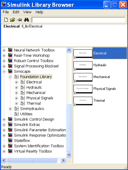
The physical component diagram is assembled by gathering the constitutive
components from the Foundation Library of the SIMSCAPE Library Browser,
which can be accessed from the SIMULINK Library Browser (fig. D.2). The
SIMSCAPE components are grouped by categories into different libraries of
components (Electrical, Hydraulic, Mechanical, Physical Signals, Thermal) and
Utilities.
Fig. D.2 The SIMSCAPE Library browser
D.2 Creating a Model 241
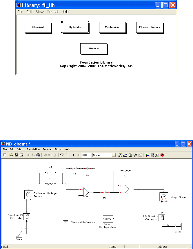
Once we access SIMSCAPE, a new model must be created by dragging
components from the Foundation Library browser to this new model window,
by selecting the appropriate library where the searched component is included
(fig. D.3).
Fig. D.3 The Foundation Library of SIMSCAPE
D.2 Creating a Model
In order to explain the process followed to create a SIMSCAPE model, we have
selected an electronic circuit system which performs the PID controller function
(fig. D.4).
Fig. D.4 PID electronic circuit in SIMSCAPE
242 Appendix D: The SIMSCAPE Modeling Environment Tutorial
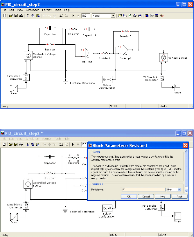
In first place we have to collect all components necessary to build the PID
controller from the Foundations Library. Afterwards, we will connect the selected
components to implement the physical components diagram, also changing the
parameters of these components if it is necessary. Finally the system is simulated
by selecting the appropriate solver options.
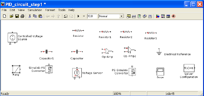
Therefore, as first step, we open a new component model, dragging the
constitutive components of the physical components diagram from each one of the
components libraries where they are included (fig. D.5).
As second step, we connect these components following the desired connection
pattern as indicated in the PID electronic circuit (fig. D.6). Possibly, it will be
necessary to flip or rotate some components or to derive some pickoff points.
Afterward, in a third step we have to change the component’s parameters
according to the values defined in the original PID electronic circuit if it is necessary,
adding optionally labels both to identify the signals transferred between components
or to name specific components (fig. D.7). Component parameters can also be
defined from the MATLAB workspace and used in SIMSCAPE. In this case we have
assigned the resistors, capacitors, gains, and ramp slope values as
>> R1=153.85*10^3;
>> R2=153.85*10^3;
>> R3=10*10^3;
>> R4=197.1*10^3;
>> C1=10*10^-6;
>> C2=10*10^-6;
>> ramp_slope=0.1;
Fig. D.5 Building process for the PID circuit (step 1)
D.2 Creating a Model 243
Fig. D.6 Building process for the PID circuit (step 2)
Fig. D.7 Building process for the PID circuit (step 3)
Before simulation is run, we must select the appropriate simulation time and the
numerical method used. For this case, we have to choose between ode15s and
ode23t, according to the instructions to be followed by the SIMSCAPE assigned
solver (fig. D.8).
244 Appendix D: The SIMSCAPE Modeling Environment Tutorial
Fig. D.8 Definition of the solver configuration for the PID circuit.
Finally, the simulation is run by double-clicking on the icon and output
responses can be viewed by double-clicking on the Scope block to view its output.
Hit the auto-scale button to see the ramp response of the PID circuit controller for
a ramp slope of 0.1 (fig. D.9).
Fig. D.9 Ramp response of the PID using SIMSCAPE
D.3 SIMSCAPE Libraries
SIMSCAPE contains a large number of components from which physical models
can be built. These components are arranged in Components Libraries which are
accessed by the main SIMULINK window.
D.3 SIMSCAPE Libraries 245
The set of Component Libraries we are going to describe contains the main
blocks used for analysis, modeling and control of dynamic systems, mainly
composed of electrical, hydraulic, mechanical, and thermal components, together
with physical signal blocks utilized to define components with more complicated
physical relations.
D.3.1 Electrical Library
This section is an introduction to the Electrical Library of SIMSCAPE. We will
illustrate the components included in this library (fig. D.10).
Fig. D.10 The SIMSCAPE Electrical Library
The Electrical Library is composed of three sub-libraries, termed the Electrical
Elements, Electrical Sensors, and Electrical Sources libraries.
Fig. D.11 The SIMSCAPE Electrical Elements sub-library
The Electrical Elements library contains some of the common elements which
constitute the electric and electronic networks, both linear (capacitor, inductance,
resistance, etc.) and nonlinear (diode, switch, etc.) together with the
electromechanical converters (fig. D.11).
The Electrical Sensors library contains both a voltage and a current sensor to be
placed in parallel or series with the element whose magnitude is being measured
(fig. D.12).
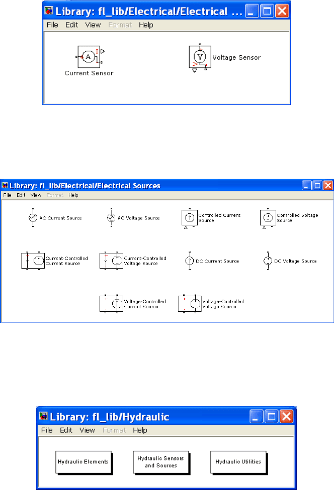
246 Appendix D: The SIMSCAPE Modeling Environment Tutorial
Fig. D.12 The SIMSCAPE Electrical Sensors sub-library
The Electrical Source library contains both voltage and current (AC and DC)
sources, either fixed or voltage/current controlled to be used as electric sources for
the model (fig. D.13).
Fig. D.13 The SIMSCAPE Electrical Sources sub-library
D.3.2 Hydraulic Library
This section is an introduction to the Hydraulic Library of SIMSCAPE. We will
illustrate the components included in this library (fig. D.14).
Fig. D.14 The SIMSCAPE Hydraulic Library
The Hydraulic Library is composed by three sub-libraries, termed the Hydraulic
Elements, Hydraulic Sensors and Actuators, and Hydraulic Utilities libraries.
D.3 SIMSCAPE Libraries 247
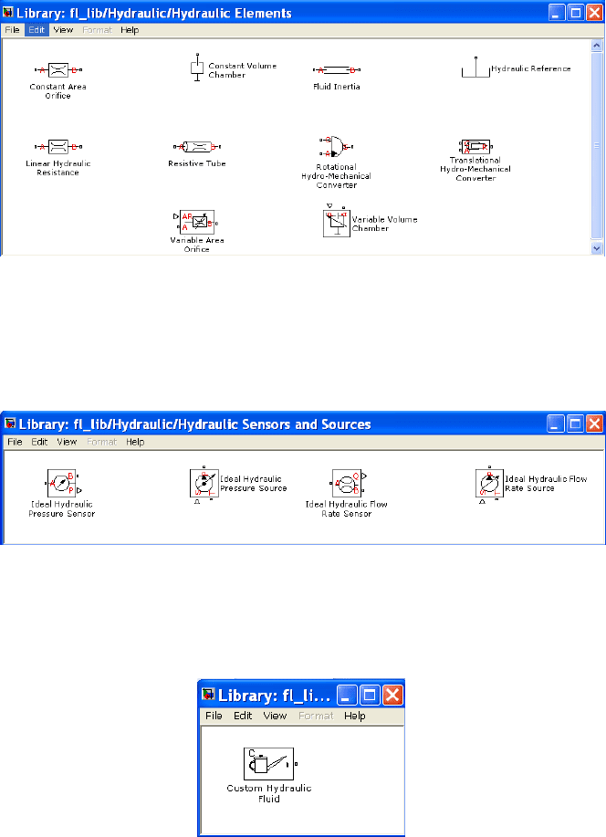
The Hydraulic Elements library contains some of the common elements which
constitute the hydraulic circuits (resistance, inertance, capacitance,..) together with
the hydromechanical converters (pump and piston) (fig. D.15).
Fig. D.15 The SIMSCAPE Hydraulic Elements sub-library
The Hydraulic Sensors and Actuators library contains both pressure and flow
sensors and sources in order to measure or actuate over the hydraulic circuit
elements (fig. D.16).
Fig. D.16 The SIMSCAPE Hydraulic Sensors and Actuators sub-library
Finally, a element to define the characteristics of fluid used by the hydraulic circuit is
also included, into the Hydraulic Uilities library (fig. D.17)
Fig. D.17 The SIMSCAPE Hydraulic Utilities sub-library